Electrical Design
This section provides electrical site design specifications for the Power Block and Power Link 1000.
The default Express Plus installation requires service wiring installed underground. (If a site requires surface mounting, contact ChargePoint before beginning work, to obtain an approved installation method.) Conduit and wire size are determined based on the length of runs from the electrical panel to the station location. Service wiring in conduit, or armored cable, must be run as required to comply with local electrical codes. Consult national and local codes or a project engineer to determine the grade, quality, and size of the conduit or cable.
The Power Block is available in 250, 300, 350, and 500 A versions, each with its own fuses and rating labels.
All wiring and conduit is supplied by the contractor unless otherwise indicated.
Upstream Components
Charging stations are considered continuous load devices (EVs draw maximum load for long durations). Therefore, electrical branch circuits to EV![]() Electric Vehicle chargers must be sized at 125% of the load on each leg of a 3-phase panel for North American installations, in accordance with National Electric Code requirements. For other regions, refer to local code.
Electric Vehicle chargers must be sized at 125% of the load on each leg of a 3-phase panel for North American installations, in accordance with National Electric Code requirements. For other regions, refer to local code.
When planning multiple EV![]() Electric Vehicle charging stations, it is best practice to segment non-continuous and continuous loads, with all branch circuits for EV
Electric Vehicle charging stations, it is best practice to segment non-continuous and continuous loads, with all branch circuits for EV![]() Electric Vehicle charging on a dedicated electrical panel assembly with adequate circuit breakers. When sizing new electrical panels dedicated for EV
Electric Vehicle charging on a dedicated electrical panel assembly with adequate circuit breakers. When sizing new electrical panels dedicated for EV![]() Electric Vehicle charging, all branch circuits must support continuous load.
Electric Vehicle charging, all branch circuits must support continuous load.
Each Power Block requires its own service panel breaker as follows:
|
Nominal Voltage |
Input Current Rating |
Branch Circuit Capacity and Breaker |
Breaker Size |
|---|---|---|---|
|
Europe: 400 V |
315 A |
350 A or 400 A |
400 A |
|
North America: 480 V |
260 A |
350 A or 400 A |
In areas with frequent thunderstorms, add surge protection at the service panel for all circuits.
Ensure all power and ground connections, especially those at the breaker and bus bar, are clean and tight. Remove all oxide from all conductors and terminals before connecting the wiring.
The Power Link 1000 charging station is tested to IEC 61000-4-5, Level 5 (6 kV @ 3000 A) standards.
AC Disconnect Switch
A local AC disconnect switch, separate from the shunt trip wiring, is recommended to be installed between each Power Block and the electrical panel. This is especially important if the main electrical panel or utility room is distant, out of line of sight, or has restricted access. For North America installations, refer to disconnect switch requirements per NEC![]() National Electric Code Article 625, “Electric Vehicle Charging and Supply Equipment Systems”.
National Electric Code Article 625, “Electric Vehicle Charging and Supply Equipment Systems”.
Transformer Configuration
Refer to the following table to configure electrical service.
|
|
North America |
Europe |
|---|---|---|
|
Input Rating |
480 VAC, 3-phase, 260 A, 60 Hz |
400 VAC, 3-phase, 310 A, 50 Hz |
|
Electrical Service Configuration |
277/480 3-phase plus ground, grounded WYE (Y) configuration(*) |
230/400, 3-phase plus ground, grounded WYE (Y) configuration(*) |
|
Product Connection |
3-phase 480 plus ground (neutral not used) |
3-phase 400 plus protective earth (neutral not used) |
(*) Delta (floating or grounded) is not supported
Neutral is not required for system operation, however Neutral-to-ground bonding is required at the Main Distribution Panel (MDP) supplying the charging station.
Shunt Trip Wiring
The Power Block provides a set of unpowered (dry) contacts to connect to an optional shunt trip device. These contacts are rated to 240 VAC and 6 amps.
Wiring sections to and from the Power Block are deactivated when unsafe conditions are detected, such as unintended cover panel removal. A breaker reset is required any time the shunt trip is activated.
If installed, each Power Block must be wired to the shunt trip unit of its own upstream circuit breaker. Upstream AC power must be shut off at the panel to remove shock risk inside the Power Block. All shunt trip behavior is already hard-coded into the charging station and has no programmable variables.
Emergency stop devices are governed by local and regional codes and may be required in some sites. If one is required by code or by the site, confirm specifications with your ChargePoint representative.

-
Electrical panel
-
Power Block
-
Control voltage supply, maximum 240 VAC
-
Shunt trip circuit breaker
-
Shunt trip coil
-
Auxiliary contacts (closed when main contacts are closed)
-
Three-phase AC main
-
Power Block shunt trip contacts, Normally Open (inside the auxiliary power supply, accessible on field wiring terminal block)
-
Three-phase Power Block AC input
Grounding Requirements
-
The Power Block must be connected to a grounded, metal, permanent wiring system.
-
North America: A service ground conductor must be run with circuit conductors and connected to an equipment-grounding terminal on the Power Block.
-
Europe: Use TN-S
 Terra Neutral Separate or TN-C Terra Neutral Combined-S configurations. (TT is not recommended because it requires RCDs.)
 -
Ensure a grounding conductor that complies with local codes is properly grounded to earth at the service equipment or, when supplied by a separate system, at the supply transformer.
-
The Power Block must be connected to a grounded, metal, permanent wiring system. An equipment-grounding conductor must be run with circuit conductors and connected to an equipment-grounding terminal or lead on the Power Link 1000.
-
All charging components must be bonded to one another in sequence: either Power Block to Power Link 1000, or Power Block to distribution cabinet (if used) to Power Link 1000.
-
Some regions also require a grounding rod to be installed adjacent to each component. Check local code to ensure compliance.
Power Link 1000 Site Considerations
This section provides electrical site design considerations specific to the Power Link 1000:
Maintenance Switch
ChargePoint strongly recommends selecting the maintenance switch option on each Power Link 1000 for fleet implementations, to improve system uptime during maintenance. For Power Link 1000s that do not have an internal or external DC disconnect switch, servicing the station requires the Power Block upstream to be powered off. This can affect system uptime and fleet scheduling.
Power Link 1000s have two options for disconnecting DC power. The station can be purchased with an optional maintenance switch already installed in the station body, or an external switch can be added between each Power Link 1000 and its Power Block if preferred. External DC disconnect switches are required to have Normally Closed (NC) contact feedback wired into the Power Link 1000.
For stations with the internal maintenance switch, the disconnect feedback positively conveys to the Power Link 1000 that the DC connection is open upstream, and the unit can be serviced safely.
If the Power Link 1000 detects its door is opening but the disconnect status is absent, or the disconnect is closed, the station signals the upstream Power Block to disable its output to prevent a shock hazard. The system software keeps the Power Block outputs disabled until the site owner clears all needed safety checks.
Ethernet to USB
Ethernet to USB![]() Universal Serial Bus is an optional kit that allows an Express Plus cluster (interconnected Power Blocks and Power Links) to have a hardwired Ethernet connection with an external network server.
Universal Serial Bus is an optional kit that allows an Express Plus cluster (interconnected Power Blocks and Power Links) to have a hardwired Ethernet connection with an external network server.
The Ethernet to USB![]() Universal Serial Bus kit is installed within a single Power Link, providing network connection for every node in the Express Plus cluster. The installation requires a conduit for the Ethernet cable, which must be run from the customer server or network equipment directly to the Power Link.
Universal Serial Bus kit is installed within a single Power Link, providing network connection for every node in the Express Plus cluster. The installation requires a conduit for the Ethernet cable, which must be run from the customer server or network equipment directly to the Power Link.
This kit must be ordered separately and installed in the field.
Wiring Requirements
For full product specifications, refer to the Express Plus Datasheet. Using that data, ensure the installation location is equipped with service wiring that supports the Express Plus site’s power requirements:
-
For AC and DC high voltage (HV
High Voltage), high current wiring, use copper or aluminum wires rated for 90 °C (194 °F).-
AC high current wires can be THHN
Thermoplastic High Heat-Resistant Nylon-Coated/THHW Thermoplastic High Heat-Tesistant, Water-Resistant/THW Thermoplastic Heat-Resistant, Water-Resistant-2/THWN-2 based on site condition (dry or wet) and rated for 600 V. -
DC HV
High Voltage wires can be XHHW/XHHW-2 based on site condition (dry or wet) and rated for 1000 V.
-
-
For low voltage (LV
Low Voltage) DC wiring, use only copper wires (XHHW/XHHW-2 based on site condition, dry or wet) rated for 1000 V and 75 °C (167 °F). -
Use copper lugs for copper wires and aluminum lugs for aluminum wires. The lugs must be nickel, tin, or silver plated compression (not mechanical) lugs. Nickel-plated lugs installed with dielectric grease is recommended.
In regions that do not use conduit, armored cable may be laid in the same configuration to conform to the wire placement on mounting templates.
For North American installations, per UL 2202, overhead configurations must use no more than three conductors per pole, and those three conductors cannot be larger than 85 mm2 (3/0 AWG![]() American Wire Gauge). Reference UL code for wire bend limitations for 203 mm (8 in) of available space.
American Wire Gauge). Reference UL code for wire bend limitations for 203 mm (8 in) of available space.
Notes For All Wiring Regions
-
Use one input feed per Power Block.
-
The maximum wiring run length is 100 m (328 ft) between a Power Block and each of its Power Link 1000s for DC conductors, 48 V DC wiring, and Ethernet.
-
48 V DC wiring must be rated for 1000 V.
-
Power Link 1000 conduit must be sealed to maintain a Pollution Degree 2 environment.
-
All sizes are generic and provided for reference only. The installation contractor must perform site-specific wire sizing, taking into account run length, site conditions, and applicable codes.
-
Ethernet requirements
-
Ethernet communication between Power Blocks and Power Link 1000s and between Power Link 1000s and external network servers must be outdoor rated Cat6 Shielded Twisted Pair (STP
Shielded Twisted Pair) cable. Lesser grades of cable do not have the required noise immunity. -
An Ethernet cable connecting a Power Block and a Power Link 1000 must have the shield terminated at the Power Block end.
-
Maximum Wire Sizes
The tables provide the largest possible wire sizes in each case. All sizing assumes a maximum ambient temperature of 50 °C (122 °F). Actual wire sizing and types should be designed to be site-specific.
48 V DC Power
|
Type |
Wire Insulation Rating |
Size (Max.) |
Conduit Trade Size (Max.) |
|---|---|---|---|
|
48 V DC |
1000 V DC |
16 mm2 (6 AWG |
21 mm (3/4 in) |
AC Input
|
Wire |
Quantity |
Size |
Lug Size |
|
|---|---|---|---|---|
|
|
AC input |
Max. 12 (four per pole) |
Max. 400 mm2 (750 MCM) |
Long barrel and tongue with two holes 44.5 mm (1-3/4 in) apart and must fit M12 stud. Max. tongue width is 47.5 mm (1-7/8 in) |
|
|
Ground |
One per Power Block |
Refer to the local code for size. |
Short barrel and tongue with single hole and must fit M12 stud. |

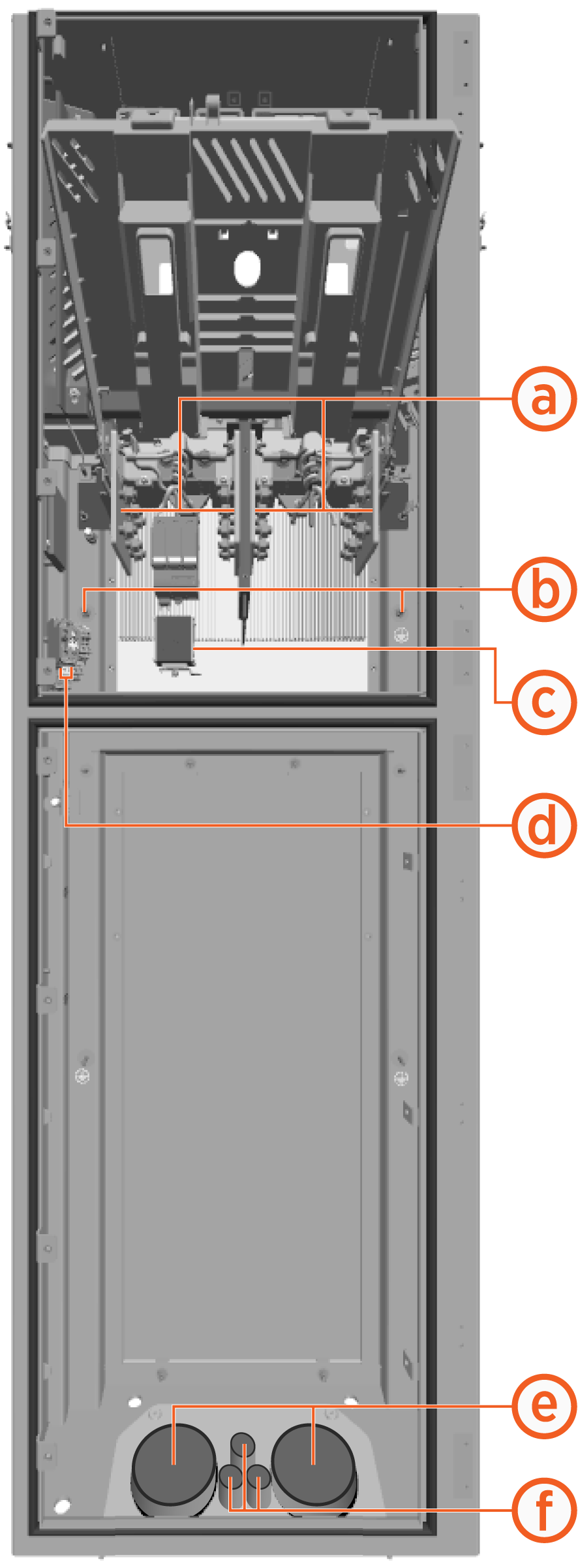
DC Output
The Power Link 1000 can be installed with maximum of six HV![]() High Voltage wires per DC input (maximum three per pole).
High Voltage wires per DC input (maximum three per pole).
The DC output of Power Block is the DC input for Power Link 1000.
|
|
Wire Landing |
Max. Wire Quantity x Size |
Max. Conduit Quantity x Size |
Lug Size |
|
|---|---|---|---|---|---|
| (a) |
350 A, 1000 V DC input
|
12 x 95 mm2 (3/0 AWG (six per input, three per pole)
|
(e) 2 x 91 mm (3.5 in) (six HV
|
Long barrel and tongue with two holes 44.5 (1.75 in) apart, must fit M12 (1/2 in) stud, Max. tongue width 31 mm (1.22 in) for (a) and 23.4 mm (0.92 in) for (b). |
|
| (b) |
Ground connection |
2 x 50 mm2 (1/0 AWG |
Short barrel and tongue with single hole, must fit M6 stud. |
||
| (c) |
Ethernet connection |
1 x outdoor rated Cat6 STP |
(f) 3 x 21 mm (3/4 in) (two LV |
N/A |
|
| (d) |
48 V DC input |
Min. 2 x 16 mm2 (6 AWG Max. 2 x 25 mm2 (4 AWG (two per input, one per pole) |
North American Requirements
|
|
Inputs to Power Block |
Power Block to Each Power Link 1000 |
|||
|---|---|---|---|---|---|
|
|
AC and Gnd |
Shunt Trip / EPO |
HV DC Output |
48 V DC Output |
Ethernet |
|
Circuit Voltage |
480 V AC |
< 240 V |
100 - 1000 V |
48 V |
-- |
|
Max. Current |
260 A |
6 A |
200, 250, or 350 A |
32 A |
-- |
|
Notes |
L1, L2, L3, Gnd |
|
|
Rated for 1000 V |
Outdoor rated |
UK and European Requirements
|
|
Inputs to Power Block |
Power Block to Each Power Link 1000 |
|||
|---|---|---|---|---|---|
|
|
AC and Gnd |
Shunt Trip / EPO |
HVDC Output |
48 VDC Output |
Ethernet |
|
Circuit Voltage |
400 V AC |
< 240 V |
200- 1000 V |
48 V |
-- |
|
Max. Current |
315 A |
6 A |
200, 250, or 350 A |
32 A |
-- |
|
Notes |
3p+E |
|
|
Rated for 1000 V |
Outdoor rated |
