Adapter Installation Guide
This section describes how to install an adapter that allows an Express 250 DC fast charging station to replace an Express 200. The adapter changes the locations of anchor bolts and AC wiring to fit the correct Express 250 locations.
Removing the Express 200 and installing the adapter requires one ChargePoint Certified Installer and about 2 to 2.5 hours to complete (not including epoxy cure time) before moving on to the normal charging station installation described in the Express 250 Installation Guide available at ChargePoint Product Reference Documentation.
Before You Begin
Before performing any procedure, the technician must disconnect the power to the charging station at the service panel. Follow local code to de-energize the applicable circuit and lockout/tagout the upstream breaker before proceeding. Use a multimeter and check that the power is off. Keep power off for the circuit until all cover panels are correctly reinstalled and the work is complete.
FAILURE TO FOLLOW THESE INSTRUCTIONS CAN RESULT IN SERIOUS INJURY, LOSS OF LIFE, OR PROPERTY DAMAGE.
- If the charging station is not installed, commissioned, or serviced by a ChargePoint certified technician using a ChargePoint-approved method, it is excluded from all ChargePoint and other warranties and ChargePoint is not responsible.
- You must be a licensed electrician and complete training at https://www.chargepoint.com/partners/training-certification to become ChargePoint certified and to access ChargePoint's web-based installer tools or ChargePoint Installer app.
Required Tools and Materials
For this installation, the installer must bring:
-
Online or paper copy of the ChargePoint Express 200 Charging Station Installation Guide
-
Lock out/tag out equipment
-
Headlamp
-
Safety glasses
-
Step ladder
-
Concrete drill, level feature recommended
-
25 mm (1 in) and 8 mm (1/4 in) concrete bits
-
25 mm (1 in) rebar bit if needed
-
Level
-
24 mm (15/16 in) open ended wrench
-
#2 Phillips screwdriver
-
Flathead screwdriver
-
T25 Torx driver
-
750 ml of epoxy with bonding strength of 11.7 MPA minimum, compressive strength of 82.7 MPa minimum, and tensile strength of 49.3 MPa minimum, such as Hilti HIT-RE 500 V3 (normal cure time), Hilti HY-200 (fast curing), or similar
Different epoxy types have different cure times at various temperatures. Check local temperatures for the site in advance to help choose an appropriate epoxy. -
Cable puller or fish tape
-
3-phase AC conductors, no larger than 35 mm2 (2 AWG
 American Wire Gauge), of type and length specified in site drawing
 -
Ground wire, no larger than 35 mm2 (2 AWG
American Wire Gauge), of type and length specified in site drawing -
Vacuum and/or brush
-
Marker
-
Paper towels
-
Tools for removing the Express 200:
-
5 mm tamper-resistant hex driver bit
-
5 mm hex Allen wrench
-
3 mm hex tool
-
24 mm (15/16 in) socket
-
8 mm (5/16 in) nut driver
-
Lifting equipment capable of safely removing the Express 200 (330 kg/728 lb)
-
Check Site Readiness
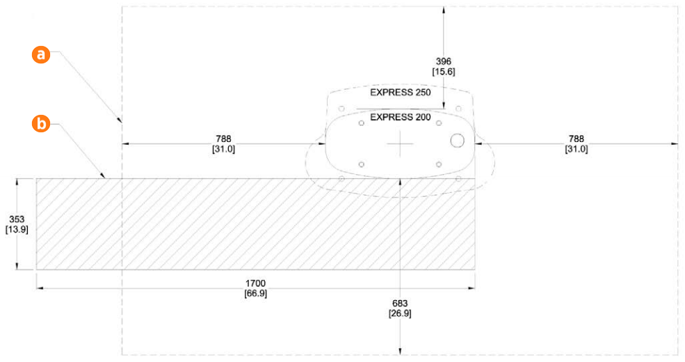
Before beginning work, check that the site meets the basic requirements outlined below, as illustrated in the following image. Measurements are listed in mm [in].
-
The panel breaker serving the charging station is either 100 A to support a maximum AC current of 80 A at 480 VAC, or 80 A breaker to support a maximum AC current of 64 A, per site drawings.
-
The smooth, level concrete pad has been approved by a structural engineer for the Express 250 dimensions and weight, OR the pad conforms to these general specifications*:
-
At least 305 mm (12 in) deep (or deep enough to be 305 mm (12 in) below the frost line)
-
At least 1296 mm (51 in) on each side
-
Contains #4 rebar top and bottom 305 mm (12 in) on center
-
Concrete 2500 PSI minimum
-
-
The service clearance (a) of open space (not necessarily at system grade) extends a minimum of 683 mm (26.9 in) beyond the Express 200 station in front, 396 mm (15.6 in) beyond the 200 in back, and 788 mm (31 in) beyond the 200 on each side.
-
There are 353 mm (13.9 in) of space at grade to the front of the station (b), extending 1700 mm (66.9 in) to the left, without any permanent obstructions, to allow important installation and service.
-
Bollards and wheel stops do not interfere with specified clearance to the front and left of the station, or can be moved by future service technicians.
-
The cellular signal strength at the station location has been tested to meet at least -90 dBm.
-
The front of the charging station faces the car being charged. This maximizes cable reach.
* These pad specifications are applicable in most conditions, as described in the Express 250 Site Design Guide available at ChargePoint Product Reference Documentation. In some extreme conditions, a larger pad would be required.
If the site does not meet these basic requirements, contact ChargePoint before continuing.
Check the Adapter Kit Contents
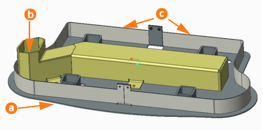
Check the contents of the Adapter Kit before beginning work. The kit includes:
-
Adapter base (a)
-
Adapter wireway (b)
-
Adapter wireway nuts, M6 PEM flush (x4)
-
Adapter skirts (x2) (c)
-
Adapter skirt nuts, M5 PEM (x4)
-
31.75 mm (1 1/4 in) diameter rigid chase closed nipple, 22.2 mm (7/8 in) overall length
-
M16 x 300 Hilti anchor bolts, 304.8 mm (12 in) long (x4)
-
M16x13x2 hex nuts (x8)
-
5/8 in ASTM F436 washers (x8)
-
Anchor bolt plastic caps (x4)
-
50 kW ratings label (optional, only applies to some sites)
Remove the Express 200
To remove the Express 200, complete the following steps:
-
Follow standard practice and local code to de-energize the applicable circuit and lock out/tag out the disconnect before proceeding. Use a multimeter to test that power is off.
-
Using the ChargePoint Express 200 Charging Station Installation Guide as reference, unfasten and remove the Express 200 charging station.
-
Disconnect the Express 200’s AC wiring at the panel.
-
Remove all old Express 200 wiring, replacing it with a pull wire.
-
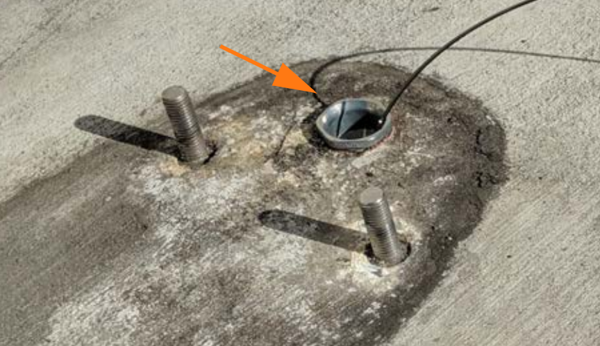
Install the closed nipple over the old wiring and onto the edge of the existing AC conduit opening. Screw the nipple into place.
-
Pull the three new AC conductors and one ground wire into place.
Neutral is not required for the Express 250. A Neutral terminal is provided for convenience only.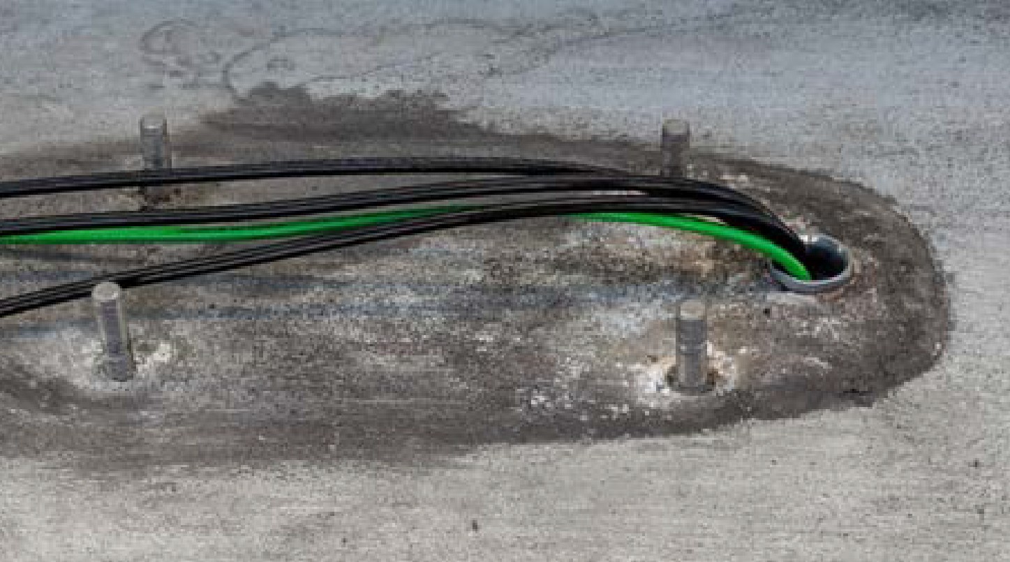
-
If present, cap the secondary conduit that housed the 120 V conductor for the Express 200. This opening is no longer needed.
-
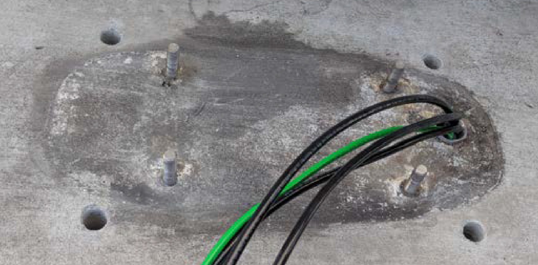
Leave the old anchor bolts in place. They will be adapted in future steps.
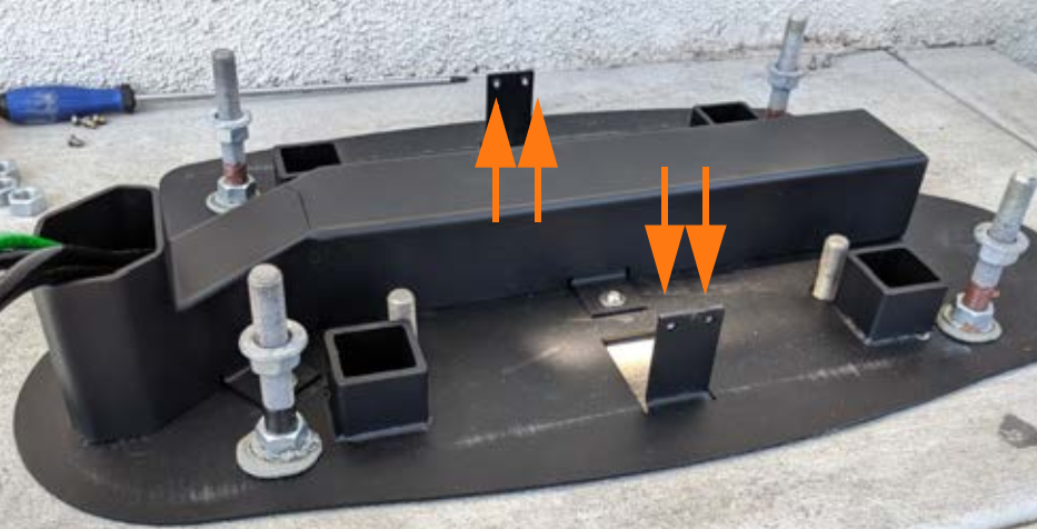
Install Surface Mount Anchor Bolts
To install surface mount anchor bolts, complete the following steps:
-
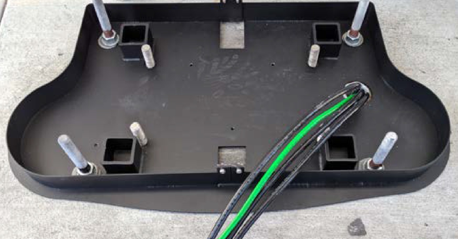
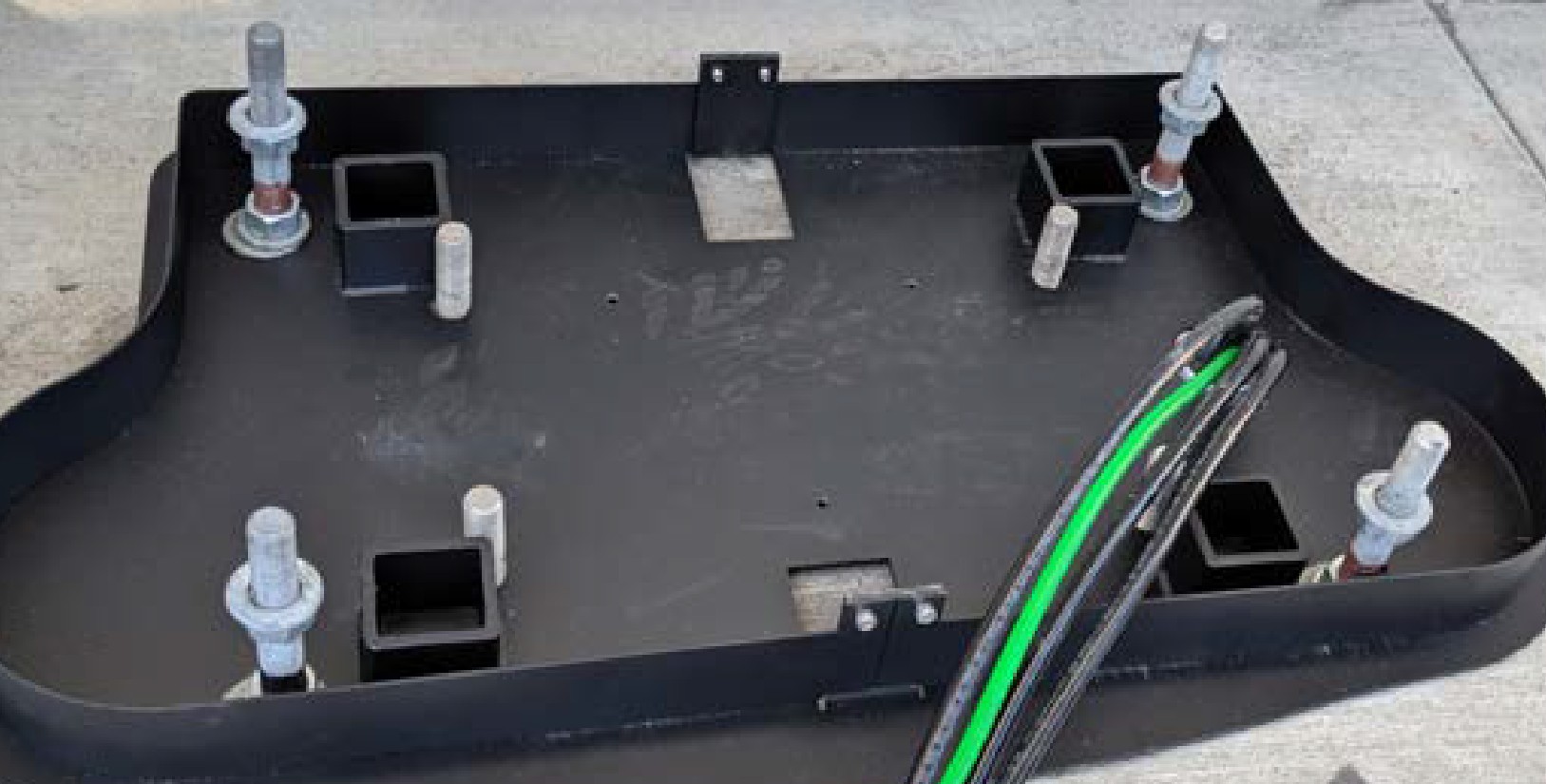
Place the adapter base over the existing Express 200 bolts (a). Check that the adapter placement on the pad meets site requirements.
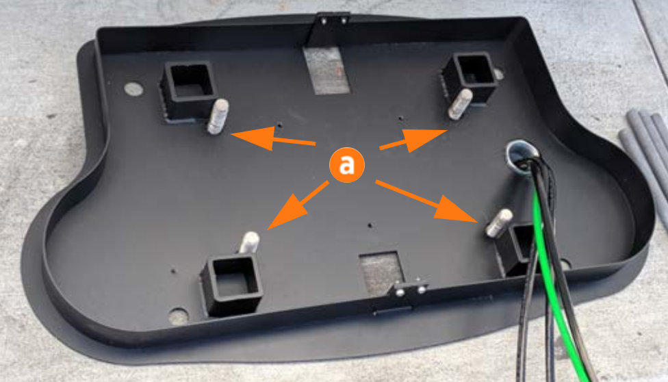
-
Use a marker to mark the locations for the Express 250 anchor bolts. Remove the adapter base.
-
Use the 8 mm (1/4 in) concrete drill bit to drill each pilot hole about 51 mm (2 in) deep. The holes must be parallel to each other and perpendicular to grade.
-
Use a vacuum or brush to clean the dust from the holes.
-
Use the 25 mm (1 in) concrete drill bit to drill each anchor hole a minimum of 229 mm (9 in) deep. Anchor bolts must have 127 mm +/- 12.7 mm (5 in +/- 1/2 in) above grade.
-
Place the adapter base over the Express 200 bolts again. Verify that the new holes for the Express 250 align with the holes in the adapter base.
-
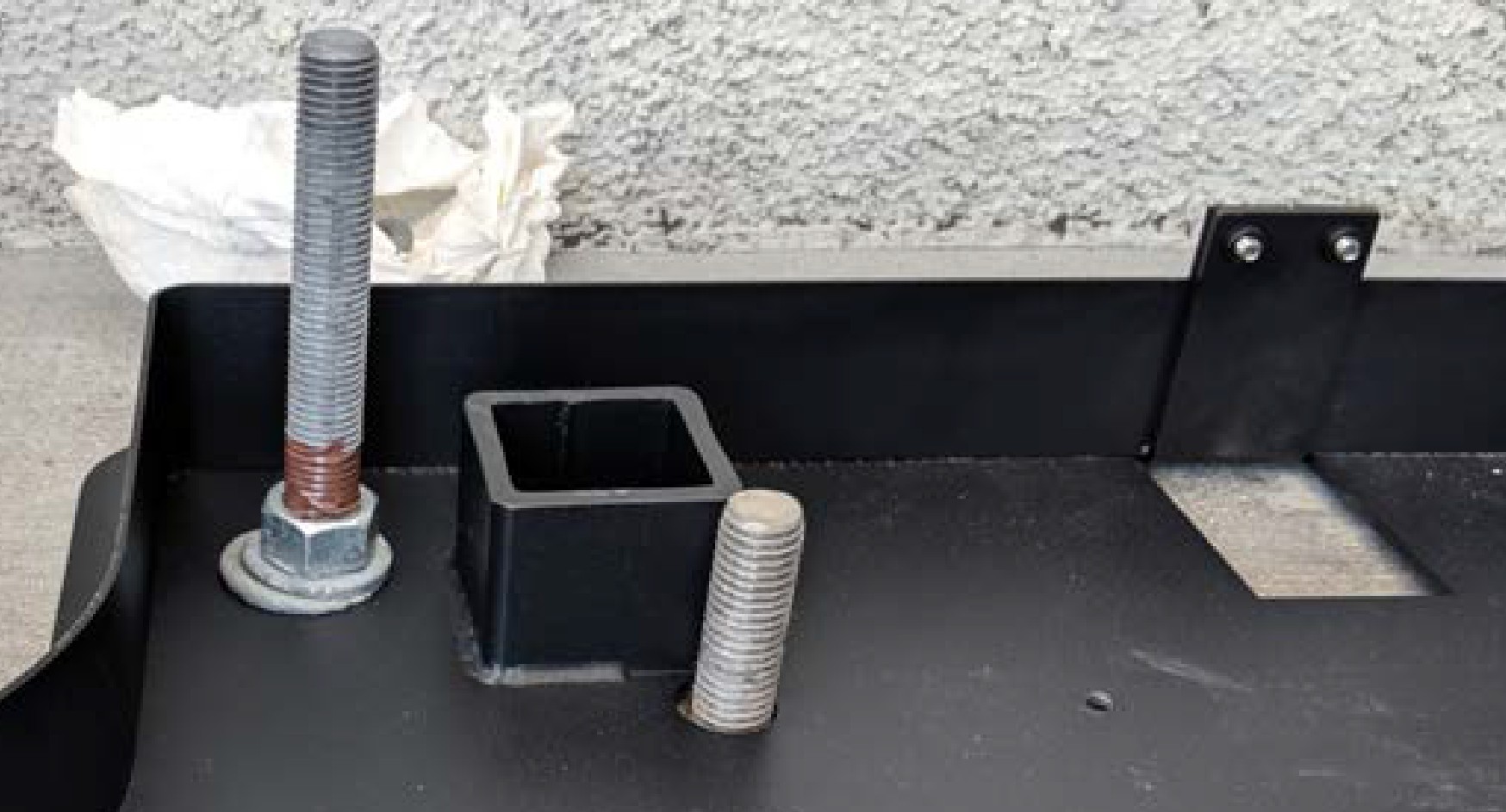
Thread a washer and a nut onto each anchor bolt, so that the measurement from the top of the nut to the top of the bolt is 101.6 mm (4 in).
-
Put a piece of tape above each nut to prevent it from floating upward when rotating the bolt into the epoxy later.
-
Prepare one of the approved types of epoxy. Ensure the applicator is dispensing correctly mixed epoxy before beginning work (for example, one Hilti epoxy is white when unmixed and grey when mixed).
-
Fill the first anchor bolt hole with epoxy until the epoxy is about 44.5 mm (1.75 in) from the top of the hole. Continue immediately to the next step before the epoxy sets (some types set in under ten minutes).
-
Insert the mounting bolt into the hole. Rotate the mounting bolt as you insert it to draw epoxy into the threads. Lift the anchor bolt again to see how close to the surface the epoxy has filled. If the epoxy is below grade level, add enough to fill the hole to grade level. Use paper towels to wipe up any excess.
-
Measure the nut distance from the top of each bolt again and adjust if needed. These nuts help secure the adapter base to the concrete and should be flush against the base when installed.
-
Use a level to check that each anchor bolt is plumb and adjust while the epoxy is still adjustable.
-
Repeat the above epoxy steps for each of the other three anchor bolts.
-
STOP. Allow the epoxy to cure for the initial cure time described in the epoxy-specific datasheet.
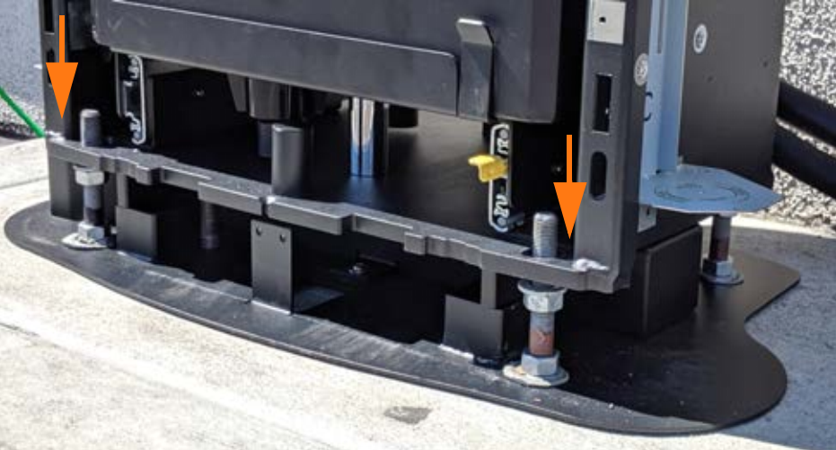
Install the Wireway
To install the wireway, complete the following steps:
-
Check that the epoxy has set completely.
-
Torque all four nuts to 94.9 Nm (70 ft-lbs).
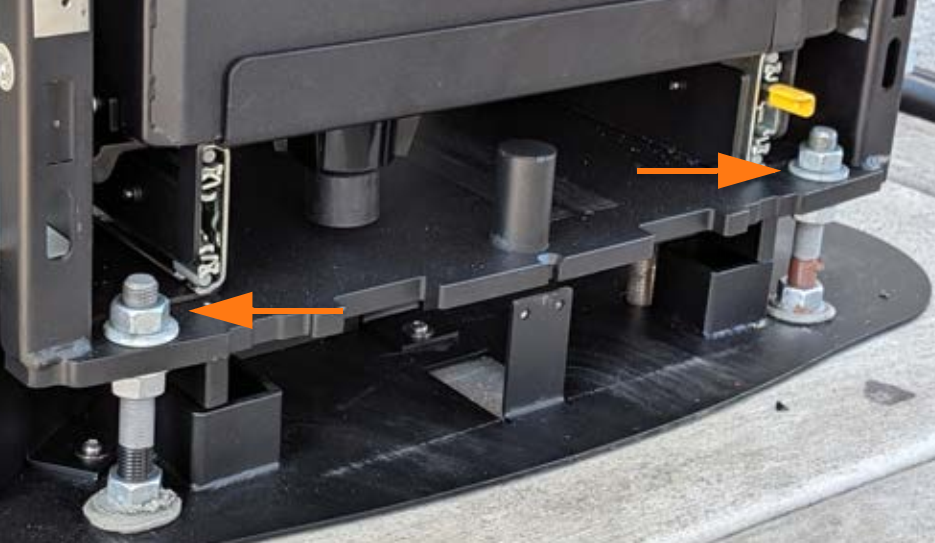
-
Install four more nuts and washers for leveling the system. Set the top of each leveling nut to 44.5 mm (1.75 in) from the top of the bolt.
Feed all three AC conductors and the ground cable, with a maximum size of 35 mm2 (2 AWG
American Wire Gauge), through the adapter wireway.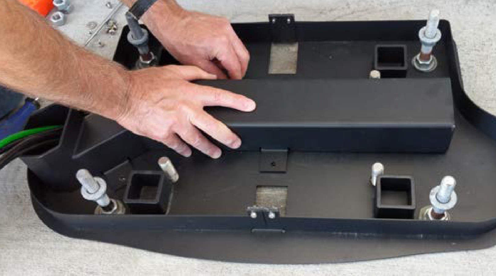
Use a T27 tool to fasten the four M6 screws that hold the wireway to the base plate. Torque to 4 Nm (35.4 in-lb).
Wait 24 hours, or until the full cure time listed on the epoxy, before beginning to install the Express 250. The rest of the materials for installing an Express 250 on top of the adapter are included with the charging station’s crate.
Continue Express 250 Installation
To continue Express 250 installation, complete the following steps:
-
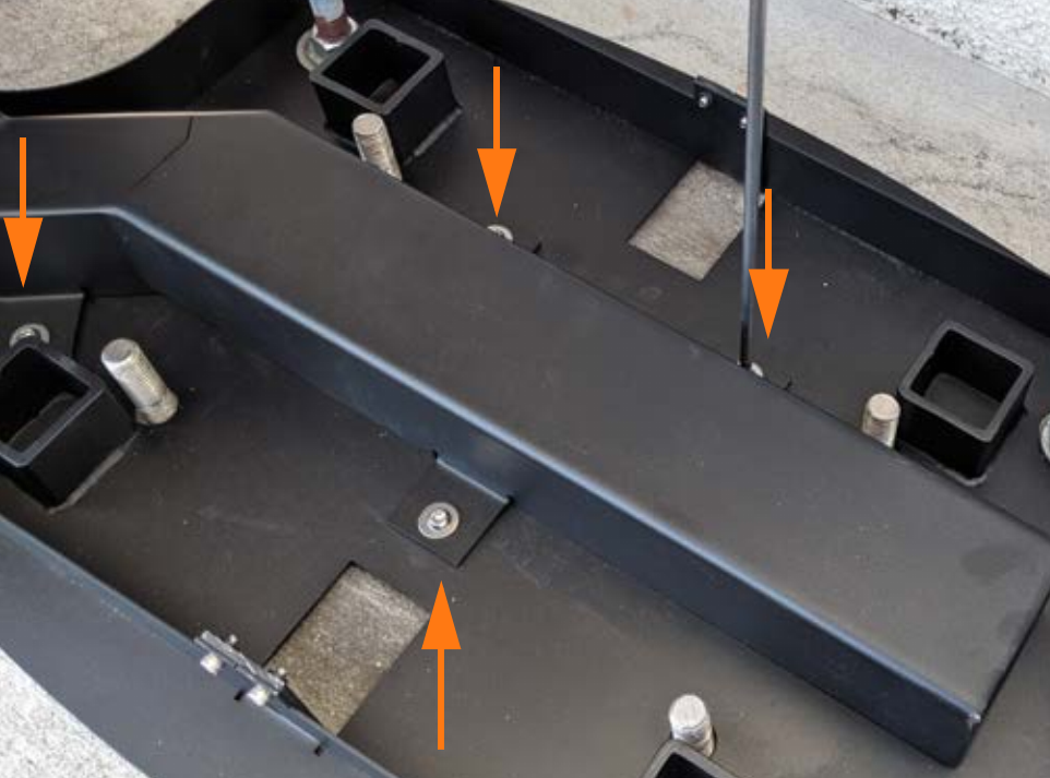
Use a T25 Torx driver to remove the four adapter skirt screws that fasten the adapter skirts to the base. Set the skirts and screws aside for later reinstallation.
 Verify that the leveling nuts on the anchor bolts are set to the higher values above (44.5 mm (1.75 in) from the top of the bolt).
 -
Receive the Express 250 at the site.
If a different team will install the Express 250, leave this guide and the adapter kit for them to complete the rest of this work. -
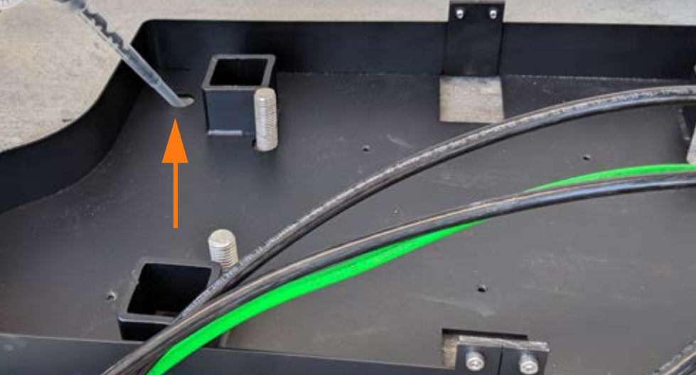
Ensure the AC rodent bracket (silver L-bracket on the left side of the station) is set high enough to not interfere with the adapter wireway when the station is mounted.
-
Follow the instructions in the Express 250 Installation Guide available at ChargePoint Product Reference Documentation up to the step of mounting the Express 250 on the anchor bolts.
-
Level the station using the leveling nuts set at the higher adapter settings.
The station should rest on the leveling nuts, not on the adapter base. -
Place the top washers and nuts on the anchor bolts over the Express 250 base plate, and lift the leveling nuts against the base plate, per the Express 250 Installation Guide.
-
If the Express 250 is being connected to wiring and a breaker of 80 A, affix the 50 kW ratings label to the station over the existing ratings, just below the swing arms in the back.
-
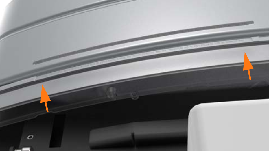
Place the two adapter skirts around the edges of the adapter, aligning the tabs of the skirts with the tabs on the base. Use a T25 Torx driver and the four adapter skirt screws to fasten the adapter skirts. Torque to 4 Nm (35.4 in-lb). When the final cover panels are installed at the end of the Express 250 Installation Guide, they fit over the outside of the adapter skirts, showing only the bottom inch of the adapter skirts. The adapter installation is now complete.
-
Continue normal installation of the Express 250 charging station per the Express 250 Installation Guide until the on-screen configuration. When prompted for either “replacement” or “new installation”, choose New.
-
Complete normal Express 250 installation.
