Express 250
ChargePoint® Networked Charging Station
Advanced FRU Guide: Repairing the Coolant Tube Assemblies
RISK OF SHOCK. Some stations share DC power (paired configuration). Pairing should be marked on the AC disconnect or breaker panel. Before performing this procedure, check for pairing and, if present, disconnect the power to BOTH stations at the service panel. Whether Standalone or Paired, follow standard practice and local code to de-energize the applicable circuit and lock out/tag out the disconnect before proceeding. Use a multimeter to test that power is off. Keep power off for this circuit until all cover panels are correctly reinstalled and the work scope is completed. FAILURE TO FOLLOW THESE INSTRUCTIONS CAN RESULT IN SERIOUS INJURY OR LOSS OF LIFE.
- If the charging station is not installed, commissioned, or serviced by a ChargePoint certified technician using a ChargePoint-approved method, it is excluded from all ChargePoint and other warranties and ChargePoint is not responsible.
- You must be a licensed electrician and complete training at https://www.chargepoint.com/partners/training-certification to become ChargePoint certified and to access ChargePoint's web-based installer tools or ChargePoint Installer app.
Do not discard the part you are replacing. Use the new Field Replaceable Unit (FRU Field Replaceable Unit) packaging to return all removed parts to ChargePoint.
For assistance, go to chargepoint.com/support and contact technical support using the appropriate region-specific number.
Required Tools and Materials
|
|
Head lamp |
|
Stepladder |
|
|
Torx screwdriver (T10, T20) |
|
T25 Security screwdriver |
|
|
Box cutter or pocket knife |
|
Gloves |
|
|
45 degree angle driver with 50 mm (2 in) long T20 Torx bit (optional) |
|
|








-
ChargePoint FRU
Field Replaceable Unit kit, coolant tube assemblies: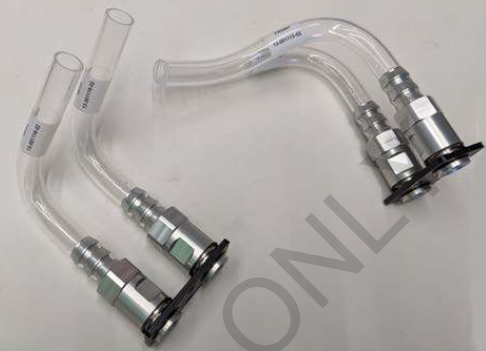
-
Assemblies, tubing and plate (x2, front and rear)
-
White tubing sheaths (x4)
-
Black hose clamps (x4)
-
T10 Torx screws, M3 flat head (x4)
-
T20 Torx screws, M4 button head (x4)
-
Short handle Torx T20 driver
-
Coolant, 60-40 LC Propylene Glycol/water, 1 gallon
-
Zip-top plastic bag, ~305 mm (12 in) square
-
18 inch coolant drain tube assembly
-
Several absorbent lint-free cloths
-
2-3 cotton swabs, 6 inch stick
-
This repair takes one technician about 1-2 hours to complete.
About Panels

All panels have guide tabs that align with corresponding slots on the product’s frame. When removing a panel, lift the panel upward to release these tabs from their slots.
Panels overlap from the bottom to the top. To remove any panel, all panels above it on that side must be removed first.
Power off the Station
Power off at the breaker panel and lock out/tag out before continuing work.
RISK OF SHOCK. Before performing this procedure, disconnect the power to the station at the service panel. Keep power off for this circuit until all cover panels are correctly reinstalled and the work scope is completed. FAILURE TO FOLLOW THESE INSTRUCTIONS CAN RESULT IN SERIOUS INJURY OR LOSS OF LIFE.
Remove the Area Light Bar
-
Using a T25 Security screwdriver, loosen the two captive screws on the area light bar.

-
Disconnect the power cable that connects the area light bar to the LED display assembly. Remove the area light bar.
When reinstalling, ensure the gasket on each end of the area light bar is properly seated around the plastic tab.
Remove the LED Display
-
Push the LED display upward to release its guide tabs from their corresponding slots on the Express 250’s frame.

-
When the LED display assembly is released, disconnect the five cables from the back.
When reinstalling, connect the five cables to their corresponding connectors on the back of the display. Leave the area light bar cable (e) loose.
(a) Communications cable (USB
Universal Serial Bus-A)(b) Holster light cable
(c) Area light cable x 2 (interchangeable)
(d) Power cable (24 V)
Do not allow the LED display to hang from its cables.
Remove the Top Front Panel

-
Using two hands, pull the top panel upward to release its guide tabs from their corresponding slots on the Express 250’s frame.
-
Place a protective cover, such as a lint-free cloth, over the touchscreen to prevent damage during service.
When reinstalling, push the bottom edge inward to position it inside the groove in the middle vent panel and engage the edge of the sign. Carefully push the panel down until it is firmly seated.
When reinstalling, ensure all five cables at the top of the panel are not captured by the front upper panel, and are easily accessible for reinstalling the LED display.
Remove the Middle Vent Panel
-
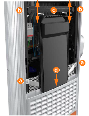
Use a T25 Torx driver to remove the M5 screw and washer (a) attaching each touchscreen ground strap to the frame. Keep the screws and washers for reuse.
-
Loosen both retention knobs (b), allowing the touchscreen beam (c) to slide up vertically and the touchscreen’s bottom edge to clear the middle vent panel’s slot (d).
-
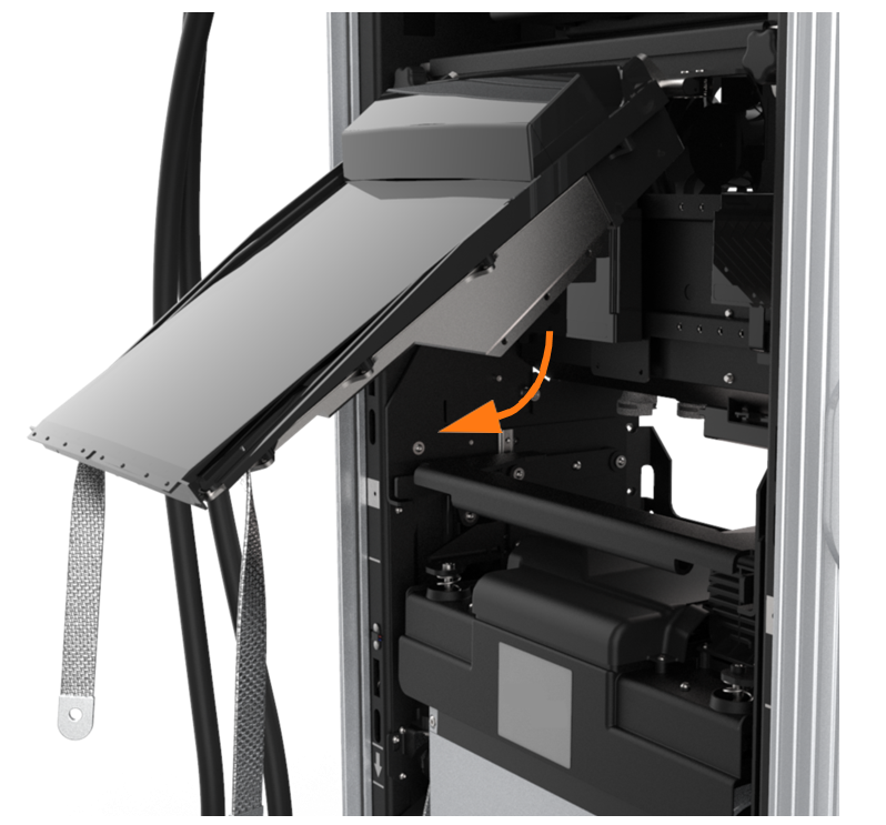
With hand pressure, tilt the touchscreen upward at a 45-degree angle.
-
Allow the touchscreen to return to its lowest position vertically.
The bottom edge and corners of the touchscreen are sharp. Take care when moving underneath the raised screen. - Disconnect all cables from the connectors on the bottom of the touchscreen and remove them from the wire management rings. Move the proximity wires to hang in front of the middle vent panel.Leave the touchscreen tilted up only when necessary to improve visibility and access to the repair area during service procedures.
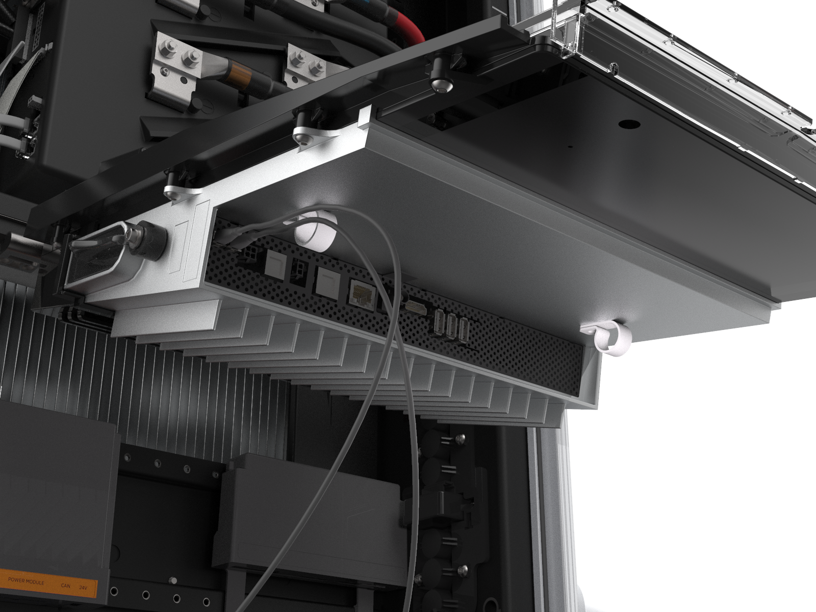
-
Loosen both retention knobs enough to remove the touchscreen completely from the station. Carefully set it aside in a safe place for reinstallation.
-
Using two hands, one on each side of the middle vent panel, remove the panel by firmly pulling it upward to release the guide tabs from the corresponding slots on the Express 250’s frame.

The fins on the back surface of the middle vent panel are sharp. Take care when handling the panel.
Remove the Bottom Front Panel
Remove the bottom front panel by lifting upward from the bottom of the panel to release the guide tabs from their corresponding slots on the Express 250’s frame.

Remove Top Rear Panel
-
Using a T25 Torx (or a Phillips #2 screwdriver for early charging stations), loosen the two hidden captive screws located in the top rear panel’s vents, inset from each bottom corner.

-
Using a T25 Torx driver, loosen the two captive screws located at the top of the top rear panel. Using two hands, hold the top rear cover at an angle to remove, leading with the bottom edge.
When reinstalling, squeeze the sides of the panel inward to fit the tabs into place in the C-channel, inside the watertight gasket.
Remove Middle Rear Panel
Using two hands, lift the middle rear panel straight up and out to disengage the guide tabs.

Small gauge wiring routed on the sides of the frame could be sheared if caught by panel tabs. Ensure wiring is cleared from guide holes when installing bottom and middle rear panels.
Remove the Bottom Rear Panel
Using two hands, carefully pull the panel upward to release the panel’s guide tabs from their corresponding slots on the product’s frame.

Open the Power Module Holders (Ground Straps)
If more room is needed to access the Hall sensor or remove side extrusions, remove grounding protections and open the Power Module holders. This procedure is optional.
Electromagnetic Interference shields instead of ground straps, refer to Open the Power Module Holders (EMI Shields) instead.
-
Use a T25 Torx to remove the front and rear M5 screws and washers attaching the Power Module holder (a) and Power Module(b) ground straps to the Express 250 frame (eight screws total). Keep the screws and washers for use in a later step.
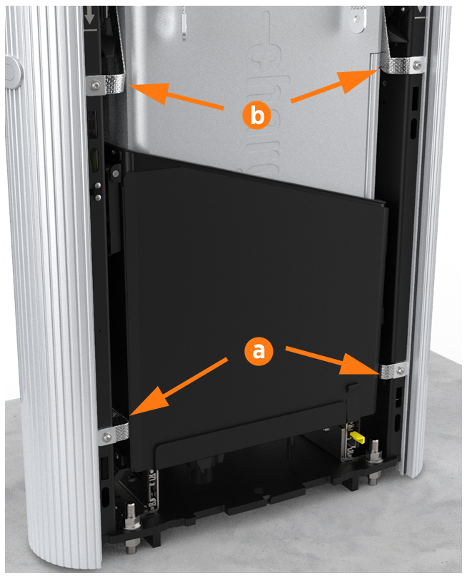
-
Using two hands, squeeze the Power Module mechanism’s release bar against the flange. Raise the bar to fully rotate the Power Module mechanism upward to the lock position. This ensures enough clearance for the Power Modules to slide under the mechanism.
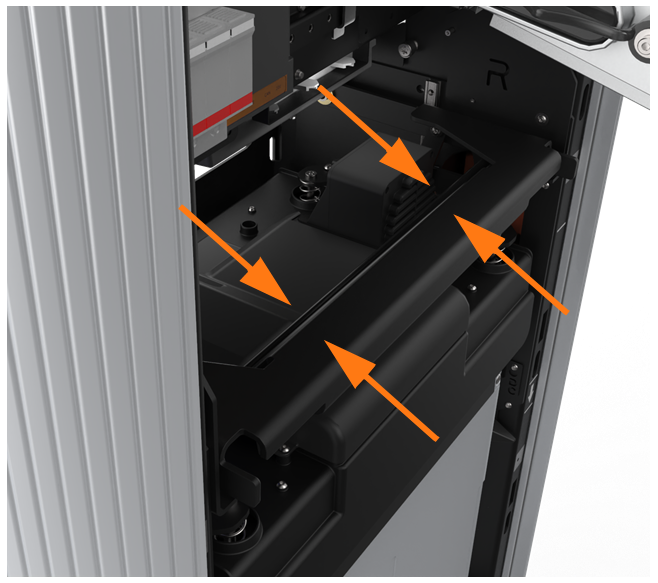
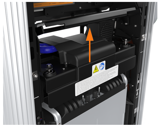
-
At the bottom right of the Express 250, press and hold the yellow release latch while pulling the Power Module tray out of the station completely.

Open the Power Module Holders (EMI Shields)
If more room is needed to access the Hall sensor or remove side extrusions, remove grounding protections and open the Power Module holders. This procedure is optional.
Electromagnetic Interference shields, refer to Open the Power Module Holders (Ground Straps) instead.
-
Use a T20 Torx to remove the top two screws and washers from the rear EMI
Electromagnetic Interference shield (a).
-
Use a T25 Torx to remove the four middle and lower screws and washers from the rear EMI
Electromagnetic Interference shield (b). The rear shield might be in one or two sections. Save all screws and washers for later reuse.When reinstalling, ensure:The cutout on the long edge is on the right side (c), leaving the sensor wire clear.
The drain hose and cooling controller cover flap are inside the EMI
Electromagnetic Interference shield.
-
Use a T25 Torx to remove the six T25 screws and washers from the front EMI
Electromagnetic Interference shield (d). When reinstalling, position the bottom cut-out over the yellow release latch (e).
 -
Using two hands, squeeze the Power Module mechanism’s release bar against the flange. Raise the bar to fully rotate the Power Module mechanism upward to the lock position. This ensures enough clearance for the Power Modules to slide under the mechanism.
-
At the bottom right of the Express 250, press and hold the yellow release latch while pulling the Power Module tray out of the station completely.
Remove Front and Rear Coolant Tube Assemblies
Use absorbent cloths to prevent glycol dripping inside the station. The repair area is
near electrical bus bars, where excess liquid could damage the system.Once the Power Modules are outside the station frame, the module mechanism handle can be moved
up and down without harm for repair access.
-
Pull out and tip over both Power Module holders outside the station. The Power Modules do not have to be removed.
-
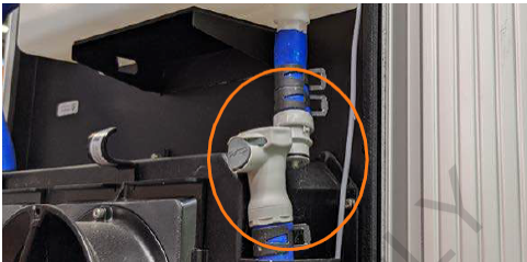
Disconnect the coolant line at the right side of the reservoir to prevent coolant flow during the process.
-
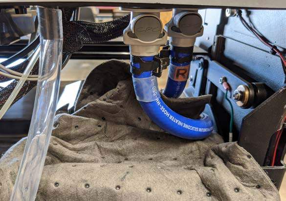
Spread an absorbent cloth under both coolant valves before disconnecting, to prevent coolant dripping into the bus bar area. Be sure to tuck it into the corners of the module mechanism.
-
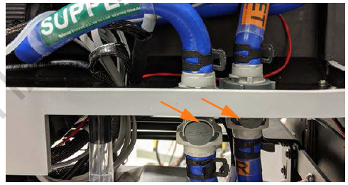
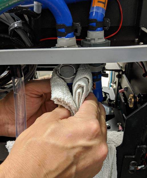
Holding each valve with an absorbent cloth, disconnect both the supply and return lines below the coolant controller shelf.
-
Use a T20 Torx (with angle driver if needed) to remove all four M4 screws from the umbrella cover that protects the tubes and the top of the module mechanism. Use the provided short handle Torx to access the rear screws. Keep the screws and umbrella for later reuse.
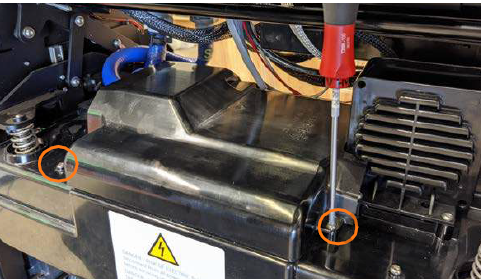
-
Route the supply and return tubes under the module mechanism handle. One at a time, hold each tube upright to fasten the quick disconnect valve onto the provided drain tube, then tip the assembly down and drain the remaining glycol from the tube into a zip-top plastic bag. Drain each tube for about 30 seconds.
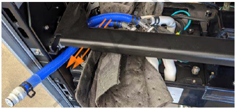
-
Disconnect the drain tube.
-
Lock the module mechanism in the up position. Place an absorbent cloth under all four coolant branches.
-
Use spring clamp pliers to release the first of four black hose clamps. Slide it, and the white outer sheath, down to show the clear tubing underneath.
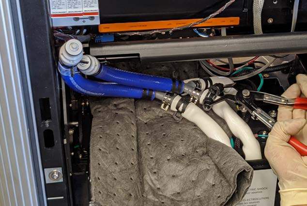
-
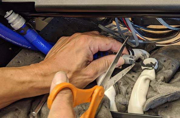
Use a box cutter or pocket knife to poke a hole in the bottom of the coolant clear tube, in case any coolant remains in the line. Ensure the hole is over the absorbent cloth.
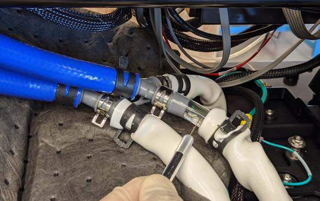
-
Once drained, use scissors to cut completely through the clear tubing to remove it from the grey splitter.
-
Repeat for all four tubes.
-
Use a heat gun to soften the four old clear tubing ends on the grey splitters. Heat each section for 45 seconds before pulling the old tubing off with needle nose pliers. Set the splitters and their blue tubes aside for later re-use.
-
Use spring clamp pliers to remove the black and silver clamps. Save all clamps for later re-use.
-
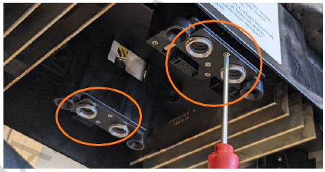
Use a T10 Torx to remove both M3 screws from each connector plate. Discard the screws. Use new screws for the kit during re-installation.
-
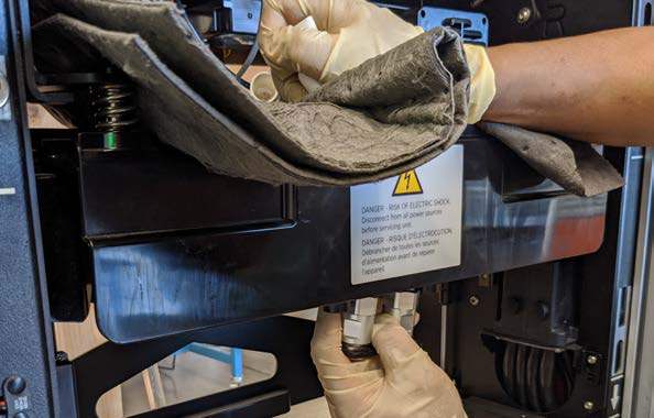
Carefully feed each connector plate with its clear tubes and white sheaths down through the module mechanism. Remove both front and rear assemblies from the station.
-
Pour any remaining coolant from each assembly into the zip-top bag and correctly dispose of the drained coolant.
Install the New Front and Rear Coolant Tube Assemblies
-
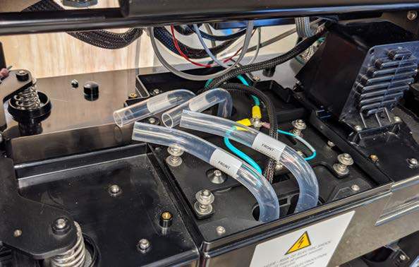
Install each new coolant tube assembly, front and rear, into their housings in the module mechanism. The front tubes are slightly longer, and both sets are labeled. Secure with two M3 screws each. Torque to 0.6 Nm (5 in-lbs).
-
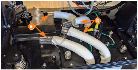
Put on flexible gloves. Use a swab to apply a small amount of glycol on the inside 50 mm (2 in) of the first new white sheath. Slide the white sheath over the clear tubing until the end touches the module mechanism.
-
Repeat for the other three tubes. In the following steps, these will be worked as two pairs of tubes (a) and (b), each with one front and one rear.
-
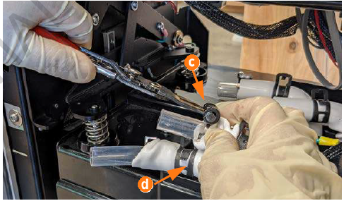
Use a swab to apply a small amount of glycol to the inside of a new black spring clamp, and the outside top 50 mm (2 in) of the white sheath. Use spring clamp pliers to slide each of the four new black spring clamps (c) over the white sheath and seat it on the assembly. Release the pliers and use a cloth to wipe off any excess glycol.
-
Use spring clamp pliers to slide each of the four silver spring clamps (d) over the clear tubing, about 50 mm (2 in) from the end, and release.
-
Note the Supply and Return labels on the loose blue tubes. Begin with the Supply tube.
-
Swab glycol into the opening of each clear tube, front and rear, closest to the left side of the station as viewed from the front. This is pair (a) in the image above.
-
Swab glycol onto the outside of each grey splitter branch on the Supply tube. Push the wet tubes onto the wet fittings until firmly seated.

-
Repeat the previous two steps with the Return tube and the other pair of front and rear clear tubes.
-
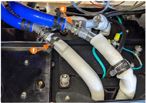
Using the spring clamp pliers, secure each silver clamp onto its clear tube where it meets the splitter fixture, between the barb and the stop ridge (e). Repeat for all four clear tubes.
-
Loosen each black clamp. Fully extend each white sheath and secure its black clamp just below the silver clamp (f).
-
Gently rotate all clamp heads to the side to prevent interference when the umbrella is replaced.
-
Lower the module mechanism handle.
-
Reconnect the two blue Supply and Return lines to the quick connect valves at the coolant connector shelf. Click each one into place and perform a pull-push test.
-
Reconnect the coolant line at the right side of the reservoir.
-
Raise the module mechanism handle and ensure the coolant tubes do not catch or bind on any parts.
-
Inspect all tubes for complete installation and absence of leaks.
-
Use a T20 Torx and four M4 screws to reinstall the umbrella cover. Use the provided short handle Torx to access the rear screws. Torque to 1.1 Nm (10 in-lbs).
-
Ensure the reservoir is full of glycol. Using a step ladder if needed, unscrew the reservoir cap and refill to the marked Max line from the jug as needed. Replace the reservoir cap.
REVERSE THE ABOVE STEPS TO REPLACE THE POWER MODULES, POWER MODULE HOLDERS, GROUND STRAPS OR EMI Electromagnetic Interference SHIELDS, REAR PANELS, FRONT PANELS, LED DISPLAY, AND AREA LIGHT BAR.
Power On the Station
Once all cover panels are installed, power on the station. The on-screen Installation Wizard steps you through any required tasks to set up the station and verify that it can operate properly.
An Installation Wizard test checks that all cover panels are correctly installed and fully seated. Check the lower right corner of the screen for any error messages. If panel errors appear, match the panel letters to this illustration.
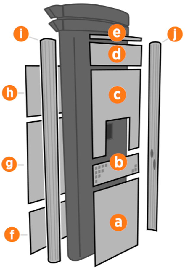
(a) Front bottom panel
(b) Middle vent panel
(c) Front top panel
(d) LED display
(e) Area light bar
(f) Rear bottom panel
(g) Rear middle panel
(h) Rear top panel
(i) Left extrusion
(j) Right extrusion
If any panel needs re-installation, review the procedures above to double-check that all panels are fully seated and that the edges of all signs are captured fully by the panels around them.
