Introduction
This topic describes how to install a ChargePoint® Express 250 DC fast charging station. An Express 250 can be installed to operate by itself (called Standalone) or to share power with one other Express 250 for higher throughput (called Paired).
- If the charging station is not installed, commissioned, or serviced by a ChargePoint certified technician using a ChargePoint-approved method, it is excluded from all ChargePoint and other warranties and ChargePoint is not responsible.
- You must be a licensed electrician and complete training at https://www.chargepoint.com/partners/training-certification to become ChargePoint certified and to access ChargePoint's web-based installer tools or ChargePoint Installer app.
Accessing ChargePoint Documentation
Access documents at ChargePoint Product Reference Documentation.
|
Document |
Content |
Primary Audiences |
|
Datasheet |
Full station specifications |
Site designer, installer, and station owner |
|
Site Design Guide |
Civil, mechanical, and electrical guidelines to scope and construct the site |
Site designer or engineer of record |
|
Concrete Mounting Template Guide |
Instructions to embed the charging station template in a concrete pad with anchor bolts and conduit placement (these may also be included in the Site Design Guide) |
Site construction contractor |
|
Surface Conduit Entry Kit Guide |
Instructions for sites where conduit cannot be run underground |
Installer |
|
Construction Signoff Form |
Checklists used by contractors to ensure the site is correctly completed and ready for product installation |
Site construction contractor |
|
Installation Guide |
Anchoring, wiring, and powering on |
Installer |
|
Operation and Maintenance Guide |
Operation and preventive maintenance information |
Station owner, facility manager, and technician |
|
Service Guide |
Component replacement procedures, including optional components |
Service technician |
|
Declaration of Conformity |
Statement of conformity with directives |
Purchasers and public |
Installing the Express 250 requires two people and takes approximately 3-4 hours. This time estimate does not include the time needed to pull DC and Ethernet cable for a Paired installation if it is not already done. Paired installation also requires contacting a ChargePoint support technician to perform any required software updates and configuration.
Check Site Readiness
The Express 250 is installed on a concrete pad. Details on how to prepare this pad are described in the Express 250 Site Design Guide.
All installations require anchor bolts (a). Standalone installations only require the two conduit stub-ups on the left side, for AC wiring and shunt trip wiring (b). Paired installations also require the wiring shown on the right: DC wiring and Ethernet communication (c).
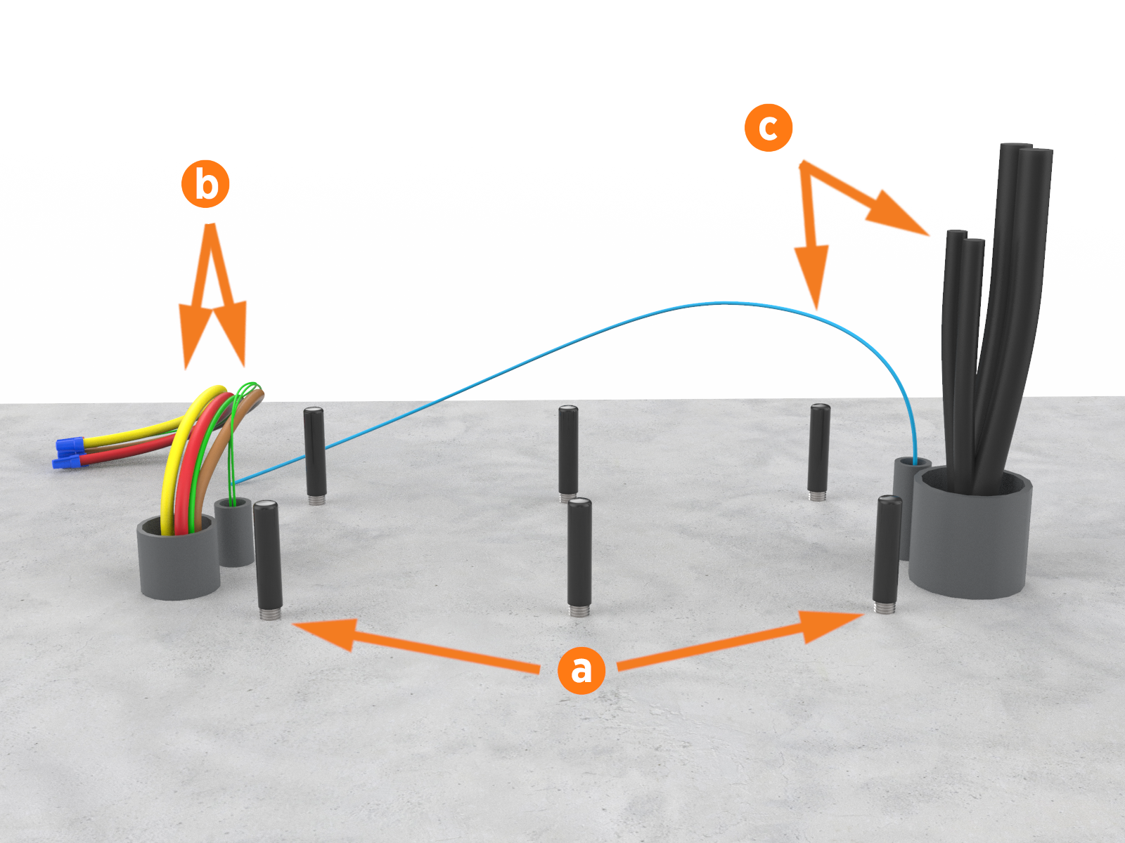
Only the four corner anchor bolts are required for station stability. Newer charging stations are designed to only use the four corner anchor bolts. If the site is already designed with six anchor bolts, removing the middle bolts is not required. Always use the leveling nuts on three corner bolts to level the system, then complete torquing instructions for all four corner nuts as described in a later section.
The Express 250 provides a set of unpowered (dry pair) contacts near the AC input terminals to connect to a shunt trip device, if desired. Refer to the Express 250 Site Design Guide for more information.
Before beginning work, check that the site meets these civil and mechanical requirements outlined below, as illustrated in the following image. Measurements are in mm (in):
-
The concrete pad is ready and the concrete is fully cured and level.
-
The concrete pad either has a site drawing approved by a structural engineer for this specific site, OR conforms to these specifications:
-
At least 305 mm (12 in) deep (or deep enough to be 305 mm (12 in) below the frost line)
-
At least 1296 mm (51 in) on each side
-
-
Walls, fences, or slopes do not prevent water from draining from the pad.
-
The concrete mounting template (CMT) is installed in the concrete pad, 50.8 mm (2 in) below the concrete surface, with anchor bolts in place in the CMT.
-
The AC conduit (max 50.8 mm/ 2 in trade size) and shunt trip conduit (max 19.1 mm/ ¾ in size) are positioned correctly in the CMT and cut down to 76.2 mm (3 in) above grade.
-
Paired only: The DC conduit (max 76.2 mm/ 3 in trade size) and Ethernet conduit (max 19.1 mm/ ¾ in size) are positioned correctly in the CMT and cut down to 76.2 mm (3 in) above grade.
-
The service clearance of open space (not necessarily at system grade) extends a minimum of 610 mm (24 in) beyond the station in front, 1276 mm (50 in) total front to back, 2156 mm (84.8 in) side to side centered on the station, and 305 mm (12 in) above the station (a).
-
The front of the station has 352 mm (14 in) of space at grade from the front right anchor, extending 1700 mm (67 in) to the left, without any permanent obstructions (bollards, wheel stops, etc) (b).
-
Charging station sites are positioned so that each station is centered on a parking space (unless curbside), with the front of the station facing the vehicle. This maximizes cable reach.
-
The charging station is at least 305 mm (12 in) from any wall as its rear clearance. Stations positioned back to back are no closer than 610 mm (24 in) shared clearance.
If the site does not meet these basic requirements, contact ChargePoint before continuing.
![]()
-
Enough space is available around the installation pad to use a forklift and other lifting equipment, unpack crates, remove packing materials, and allow two people to freely move throughout the area.
Remove any concrete that is not level with the rest of the surface, or you cannot level the Express 250. Use a grinder or a hammer and chisel to remove any bumps in the concrete.
Also ensure that these electrical requirements are in place:
-
The appropriate circuit protection, and metering is in place at the installation site.
-
A grounding conductor that complies with local codes is properly grounded to earth at the service equipment or, when supplied by a separate system, at the supply transformer.
-
A correctly rated, dedicated breaker is installed for each station, per this table:
|
Nominal Voltage |
Max AC Current |
Circuit Breaker Size |
|---|---|---|
|
400 V (EU) |
96 A |
125 A |
|
480 V (N. America) |
80 A |
100 A (125% continuous load required for N. America) |
-
Breakers have shunt trip capability if the site drawing calls for shunt trip wiring.
-
All necessary electrical infrastructure has been completed per local codes and ChargePoint specifications for 3-phase power plus ground, with properly sized wire at the station. Neutral is not required for system operation; however, neutral-to-ground bonding is required at the Main Distribution Panel (MDP) supplying the charging station.
This requirement applies to Canadian installations. Whether using a step-up or step-down auto transformer, refer to the "Hydro-Québec bulletin - Choosing the right one 600/480 V transformer" for specific guidance.
|
Voltage Rating |
Temperature Rating |
Maximum Conductor Size for Terminals |
|---|---|---|
|
EU non-armored: 600/1000 V |
90 °C |
35 mm2 |
|
EU armored: 600/1000 V |
90 °C |
35 mm2 multi-core |
|
N. America: 600 V |
90 °C |
-
Cellular signal strength is consistently strong to allow installation and station operation. Use a cellular signal detection device (such as a Snyper, Octopus, or similar) to ensure the signal is -85 dBm or better. (Note that these numbers are negative, so -70 dBm is stronger than -85 dBm, and -90 dBm is weaker.) If the signal is below -85 dBm, install multi-carrier, multi-band repeaters to boost signal strength. Repeaters are often required for installations in underground garages or enclosed parking structures.
-
Paired only: All four DC copper conductors are installed between stations as follows:
|
Voltage Rating |
Temperature Rating |
Maximum Conductor Size for Terminals |
Insulation Type |
DC Input/Output |
|---|---|---|---|---|
|
EU non-armored: 600/1000 V |
90 °C |
120 mm2 |
XLPE |
160 A |
|
EU armored: 600/1000 V |
90 °C |
120 mm2 4-core |
XLPE |
160 A |
|
N. America: 1000 V |
90 °C |
XHHW-2 |
160 A |
-
Paired only: Outdoor rated Ethernet Cat5e or Cat6 cable, without terminations, is pulled between the two stations with 3050 mm (10 ft) of service loop at each end.
For any questions about site specifications, refer to the Express 250 Datasheet and Express 250 Site Design Guide.
The Express 250 charging station is tested to IEC 61000-4-5, Level 5 (6 kV @ 3000 A) standards. In geographic areas that experience frequent thunderstorms, supplemental surge protection must be installed at the service panel.
Check Express 250 Shipping Crates
Each Express 250 ships in at least two crates. Ensure you have all crates at the installation site.
|
Contents |
Max. Shipped Dimensions |
Max. Shipped Weight* |
|---|---|---|
|
Express 250 Charging Station |
1.270 x 1.105 x 2.438 m (50 x 43.5 x 96 in) |
494 kg |
|
Power Module crate: holds 1 Power Module |
0.902 x 0.572 x 0.368 m (35.5 x 22.5 x 14.5 in) |
49.9 kg (110 lbs) |
|
*Includes the weight of the crate - for the weight of the component, see the Express 250 Datasheet. |
||
Always transport and store the Express 250 in its original packaging. Use appropriate lifting equipment (forklift, crane and lifting straps, etc). Ensure the load rating of all lifting equipment is adequate for the weight of the crated Express 250 as shown above.
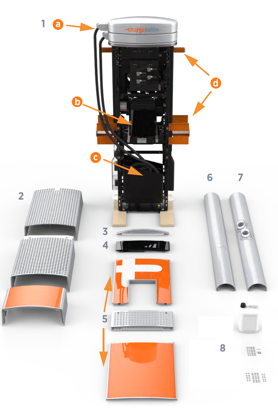
Express 250 Charging Station Crate
Leave components in the shipping crate until needed. When removing, protect them from damage (such as scratches) by placing them flat on a blanket or tarp, face up. Do not stand up cover panels, as they may be knocked or blown over. Cover charging connectors to prevent damage or ingress.
Listed below are the components:
-
Express 250 main body
-
Swing arms
-
Touchscreen
-
Charging connectors (in bin for shipment)
-
Forklift handles and crane lift guides (removed during installation)
-
-
Rear cover panels (x3)
-
Area light bar
-
LED display
-
Front cover panels (x3)
-
Left extrusion
-
Right extrusion
-
Installation kit:
16 mm (5/8 in) -11 nuts (x12)
16 mm (5/8 in) washers (x12)
M5x8 T25 Torx screws (x10)
M5 washers (x10)
Plastic caps (x2, 2 extra)
M5 x 10 T25 Torx shoulder screws with retained washers (x2, 2 extra)
Duct seal compound
EMI
 Electromagnetic Interference shields (x2) (not shown)
60/40 Propylene glycol coolant (the coolant label references its Safety Datasheet if needed)
Ethernet connector that accommodates up to 6 mm (0.24 in) OD jacketed Cat5e or Cat6 cable (for Paired installations only)
Dielectric grease (for Paired installations only)
Labels for panel breakers (for Paired installations only)
Grommets for DC rodent guard bracket (for Paired installations only):
73 mm (2 7/8 in) OD
22 mm (7/8 in) OD
ChargePoint also provides a tool kit (not shown):
-
T20 Torx security driver
-
T25 Torx security driver
-
Wago driver
-
Coolant funnel
-
2.5 cm x 183 cm (1 in x 6 ft) lifting straps
-
Printed Installation Guide
Power Module Shipping Crate
Each Power Module crate holds one Power Module each.
Stations can be ordered with one or two power modules.
It also contains a fastener kit that includes:
-
Ground stud brackets (x2)
-
M5x6 mounting screws (x8)
These brackets are only needed for Power Module replacements in older stations. New charging station installations can ignore these parts.
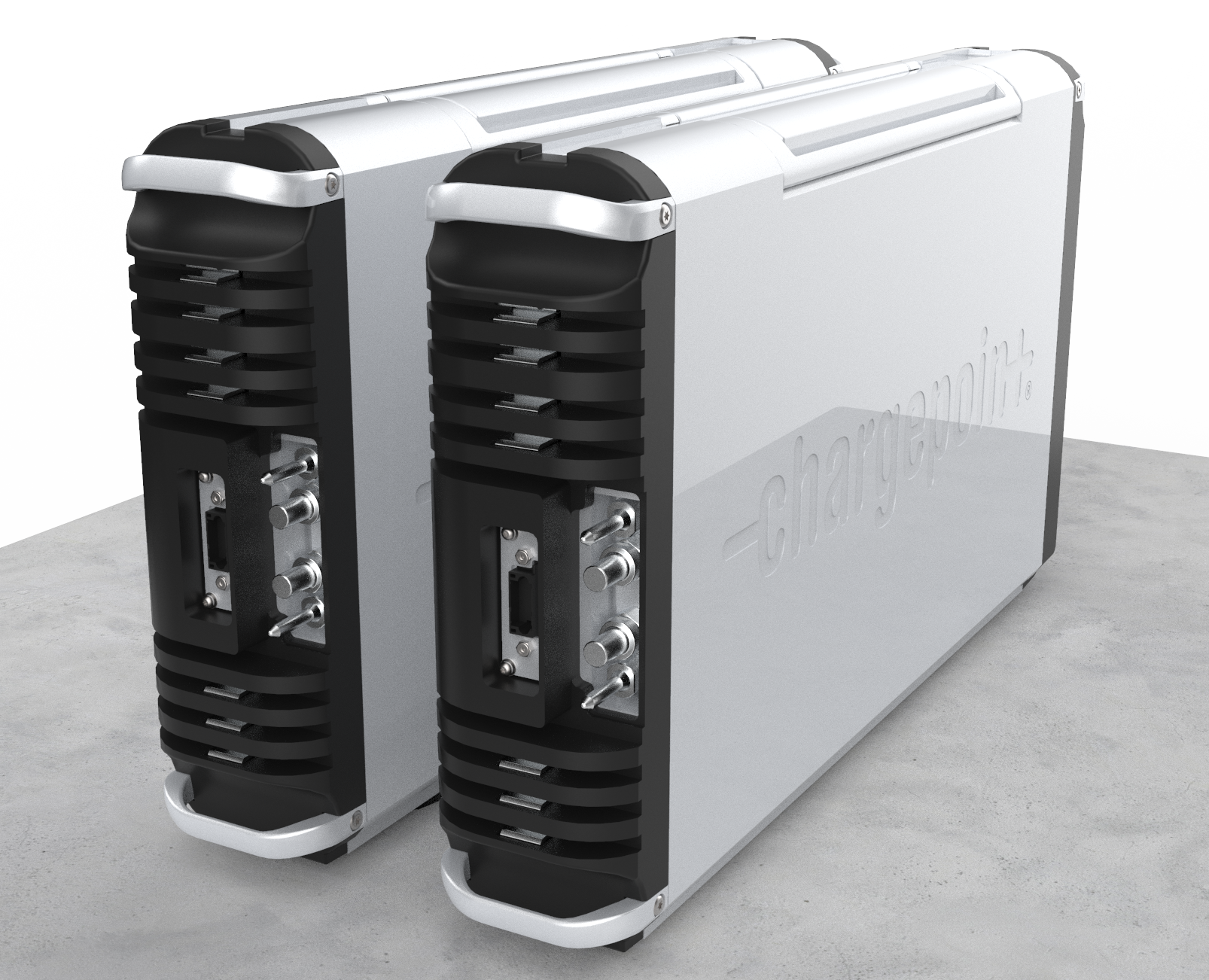
Always rest a Power Module flat on the ground until it is being installed. Power Modules are not stable in any other position. Images of Power Modules standing with the handles on top only illustrate the proper installation position.
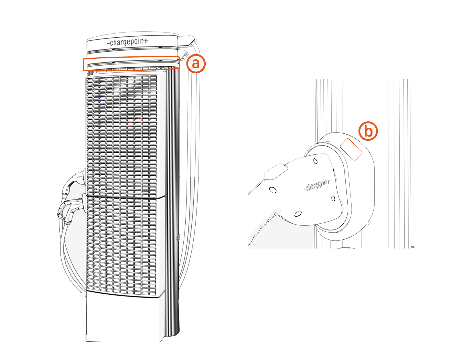
Rating Labels for Power Select
When installing a Express 250 with Power Select, additional sets of labels must be ordered with a Express 250 station. When ordering a set of labels, it will include one label to be applied below the cable swing arms (a) and one label to be applied on the charging cable holster (b).
Required Tools and Materials
In addition to the tools and materials provided by ChargePoint in product crates, an certified installer needs:
-
Lifting equipment (forklift or crane)
-
Lock out/tag out equipment
-
Step ladder
-
Cut-resistant gloves
-
Safety glasses
-
Head-mounted flashlight
-
Torque wrenches capable of 4 to 95 Nm (3 to 70 ft-lbs)
-
10 mm (3/8 in) deep socket wrench
-
18 mm (11/16 in) wrench
-
24 mm (15/16 in) wrench (x2)
-
8 mm (5/16 in) nut driver
-
10 mm (3/8 in) nut driver
-
5 mm (3/16 in) hex driver
-
#2 Phillips screwdriver with long handle
-
Cellular signal detection device, such as a Snyper, Octopus, or similar
-
Standard electrical equipment such as wire cutter, wire stripper, and cable ties
-
Level
-
Isopropyl alcohol wipes
-
Wire brush
-
If not already installed for this site, and if applicable, shunt trip wiring: size 0.08 to 2.5 mm² (28 to 14 AWG
American Wire Gauge), fine stranded or solid -
If not already installed for this site, setup the AC and ground conductors with these specifications:
|
Voltage Rating |
Temperature Rating |
Maximum Conductor Size for Terminals |
|---|---|---|
|
EU non-armored: 600/1000 V |
90 °C |
35 mm2 |
|
EU armored: 600/1000 V |
90 °C |
35 mm2 multi-core |
|
NA: 600 V |
90 °C |
If this is a Paired installation, the certified installer also needs these tools and materials:
-
Cable puller or fish tape (if not already completed on site)
-
DC conductors (x4):
|
Voltage Rating |
Temperature Rating |
Maximum Conductor Size for Terminals |
Insulation Type |
DC Input/Output |
|---|---|---|---|---|
|
EU non-armored: 600/1000 V |
90 °C |
120 mm2 |
XLPE |
160 A |
|
EU armored: |
90 °C |
120 mm2 4-core and cable gland sized to local code (such as Cablecraft CCG-CW50 or similar) |
XLPE |
160 A |
|
NA: 1000 V |
90 °C |
XHHW-2 |
160 A |
-
2 positive and 2 negative conductors; 1 positive and 1 negative in each direction
-
USA/Canada: Copper only, maximum station DC output/input current: 160 A
-
EU/UK: Rated at 1000 V conductor to conductor (+/-500 V conductor to ground, LV
Low Voltage), copper only, maximum station DC output/input current: 160 A -
DC cable run must be continuous, with no joints or splices
-
Consult site drawings for site-specific conductor size and length (Express 250 Site Design Guide provides conductor size calculation examples for reference)
-
Leave 61 cm (2 ft) of each conductor above grade at each end
-
DC lugs (x4):
-
Silver plated copper compression lug (2-hole specified for North America); tin plated is acceptable if used with dielectric grease
-
Holes for an M6 (1/4 in) stud at 19 mm (3/4 in) stud hole spacing
-
Maximum width 30 mm (1.18 in)
-
North America lug size: 3/0 or 4/0 AWG
American Wire Gauge -
Example UK/EU lugs for average conductor size are Weidmuller 1494410000 120 mm2 or similar
95 mm2 (3/0 AWG American Wire Gauge) is sufficient for most sites unless ambient temperatures are >= 40°C.
-
-
DC cable lug crimper and die that is compatible with lug size and brand
-
Multimeter with toner attachment, such as Fluke 117 or similar
-
Ethernet wiring for DC:
-
Minimum of CAT5e or better
-
Outdoor or plenum rated wiring
-
Maximum run length of 100 m (328 ft)
-
Leave 3.2 m (10.5 ft) of wire above grade at each end
-
Field crimp using straight-through pattern 568B
-
-
Ethernet crimper
-
Ethernet crimp tester capable of testing for correct 568B (split pair) pattern, such as a Klein Tools VDV526-052 VDV LAN
Local Area Network Scout Jr. Tester or similar -
Permanent marker
-
Torque paint pen
