Pair the Charging Stations

To install labels, connect the DC conductors, and connect Ethernet communication if the charging station is being paired, complete the following steps.

If the Express 250 is being installed as a Standalone station, skip this section and continue to Install Cover Panels.

RISK OF SHOCK. Power must be disconnected at the service panel to BOTH Express 250 paired charging stations when servicing. FAILURE TO CORRECTLY MARK THIS FOR FUTURE TECHNICIANS CAN RESULT IN SERIOUS INJURY OR LOSS OF LIFE.

Install New Labels

  1. Identify the ratings label area at the rear of the charging station, just under the charging cable swing arms.

  2. Wipe down the surface area with a lint-free cloth and isopropyl alcohol wipes.

  3. Peel the backing and the protective front strip from the 125 kW label. Carefully affix the new ratings label over the top of the existing ratings on the station so that there are no air bubbles and scratches. The new label reflects the updates in charging station capacity.

  4. Identify the two charging stations to be paired. For each pair, check site plans to see which charging station is designated Station 1 and which is Station 2. If the plans do not define it, designate them now.

  5. Affix the AC disconnect labels in the site’s main language to the disconnect responsible for AC power to this charging station and the disconnect for its Paired partner.

  6. Using permanent marker, write in the last three numbers of both Paired stations’ serial number (found next to the ratings) on each disconnect label, so that future technicians know which disconnect to power off for service. This is especially important for sites with multiple pairs of charging stations.

Disconnect numbers must be written in permanent marker. Normal ballpoint pen ink does not stay legible on the label.

Install DC Cables

The wiring on the DC side (the right side of the charging station) is only connected for Paired installations. Do not connect this wiring for Standalone installations.

RISK OF SHOCK. Leave the power disconnected at the service panel to BOTH Express 250 charging stations to be paired. Keep power off for both circuits until all cover panels are correctly installed and the work scope is completed. FAILURE TO FOLLOW THESE INSTRUCTIONS CAN RESULT IN SERIOUS INJURY OR LOSS OF LIFE.
The DC terminal blocks on the Express 250 can accept up to 120 mm2 (4/0 AWGClosed American Wire Gauge) maximum wire size. Check site plans and local code for site-specific requirements.
  1. Remove the plastic DC wiring cover on the right side of the Express 250 by pressing on its sides and pulling it outward.

  1. If not already done, label each end of each DC conductor to aid installation as follows:

    • Station 1 A+ on one end and Station 2 B1+ on the other end

    • Station 1 A- on one end and Station 2 B1- on the other end

    • Station 1 B1+ on one end and Station 2 A+ on the other end

    • Station 1 B1- on one end and Station 2 A- on the other end

Be sure to connect positive to positive, and negative to negative, on the same wire. Do not reverse the polarity.

  1. If not already done, pull DC conductors through the DC conduit and Ethernet wire through the communications conduit in the installation pad, as described in the Express 250 Site Design Guide.

  2. Use the multimeter and toner attachment to test each DC conductor for continuity. If any errors are found, adjust the conductor labels.

  3. Measure the length needed to extend the DC conductors from the conduit opening to the Express 250’s terminal blocks (approximately 61 cm/2 ft at each end). Do not trim wires closely yet.

Installing the rodent guard brackets as described below protects the system against pest ingress from under the station or along the wiring. Pest ingress in AC and DC terminal areas can damage the system and/or result in system downtime. Bracket installation is required.
  1. Use a flathead screwdriver to push out both punch-out discs in each DC rodent guard bracket.

  1. For North America and other regions using conduit:

    If the cable bend radius does not allow them to thread through the rodent guard bracket, use a T25 Torx to temporarily remove the bracket from the charging station. Immediately reinstall it once the cables are in place.
    1. Install the included grommets into both bracket holes, to protect wiring from the edges of the metal bracket.

    2. Route the conductors through the larger bracket hole.

    3. Route the Ethernet wire through the smaller bracket hole.

    4. Pull enough Ethernet wire to reach the port (approximately 317.5 cm/ 125 in at each end).

    5. Use a T25 Torx to loosen the two M5 screws attaching the rodent guard bracket to the charging station. Slide the bracket down to leave no gap above the conduit openings. Secure the T25 screws.

    6. Strip the DC wiring outer jackets as needed for wire management.

  1. For the UK and other regions using armored cable:

    1. Install the included small grommet into the smaller bracket hole, to protect the Ethernet wiring from the edges of the metal bracket. Do not install the larger grommet, to prevent interference with the cable gland.

    2. Use the smallest cable gland appropriate for the DC conductor size. The bracket can support up to a CW63 size gland.

    3. Use a T25 Torx to loosen the two M5 screws attaching the rodent guard bracket to the charging station.

    4. Install the lower cable gland half on the armored cable, below the rodent guard bracket.

    5. Route the DC wires through the rodent guard bracket.

    6. If the cable bend radius does not allow them to thread through the bracket, use a T25 Torx to temporarily remove the bracket from the charging station. Immediately reinstall it once the cables are in place.
    7. Route the Ethernet wire through the smaller hole in the bracket.

    8. Pull enough Ethernet wire to reach the port (approximately 317.5 cm/ 125 in at each end).

    9. Use a T25 Torx to loosen the two M5 screws attaching the rodent guard bracket to the charging station. Slide the bracket down to leave no gap above the conduit openings.

    10. Complete installation of the cable gland. Tighten the T25 screws on the bracket to secure it in place.

    11. Begin cutting, crimping lugs, and landing the DC conductors on one station only as described below, then cut and crimp lugs for the other station. Trimming and crimping for lugs on both sides at once can create misalignments from wire movement within the conduit.

  1. Complete these steps for Station 1:

    1. Measure the height of the A and B1 terminals. Trim the corresponding conductors to length.

    2. Field-crimp the end of each DC wire with a compression lug that meets the lug specifications in Bring Tools and Materials. Use the directions found with the crimp tool. If required, heatshrink or tape the crimp area to meet local code.

    3. Remove the installed washers and nuts from the DC A terminal blocks and keep them for installation use.

    4. Apply a thin coating of the specified dielectric grease on each lug.

    5. Land the DC lugs on the terminal blocks. Land the A lugs on the bottom terminal blocks, and the B lugs on the top B1 terminal blocks. Fasten each lug in this order: terminal block, lug, M6 flat washer, M6 Belleville washer with the cup facing the station, 10 mm M6 nut.

    6. Use a 10 mm (3/8 in) nut driver to torque DC lugs to 5.5 Nm (48.7 in-lb). Mark all DC connections with a paint pen.

Do not under- OR over-torque the DC fasteners. Excess torque, even with hand tools, can damage the terminal blocks.

  1. Complete the above steps for Station 2.

Install the Ethernet Wiring

Follow the below steps to install the Ethernet Wiring:

  1. Measure the length needed to extend the Ethernet wiring from the conduit opening, up the side of the frame, and into the Express 250’s Station Management Unit, located on a rail under the touchscreen (approximately 317.5 cm/125 in). Trim the excess wire.

  2. Route the Ethernet wire up the rear side of the frame, through the plastic P-clips (a), and into the top wiring hole (b).

  1. Route the Ethernet wire across the charging station from right to left between the auxiliary power supply and the contactor assembly. Zip tie the Ethernet wire to the existing cable bundle at each corner (c).

  2. Route the Ethernet wire down behind the touchscreen adjustment bar.

  3. With hand pressure, swing the bottom of the touchscreen out to a 45-degree angle (d).

The bottom edge and corners of the touchscreen are sharp. Take care when moving underneath the raised screen.

  1. Re-measure the distance to the Ethernet port of the Station Management Unit (e) and trim excess wire.

  2. Strip the end of the Ethernet insulation.

  1. Crimp the Ethernet wire in a straight-through pattern into RJ45 connectors at both ends. Note the location of Pin 1 relative to the clip in the image, and the order of the blue and green wires in the pattern.

  2. Test the Ethernet wire for functionality.

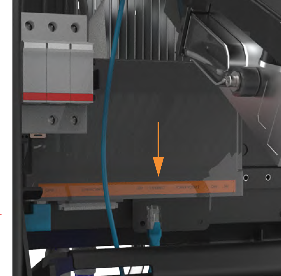
  1. Plug the Ethernet wire into the Ethernet port of the Station Management Unit.

  2. It is easier to access the Ethernet port if the Power Module mechanism handle is temporarily in the down position.
  1. Use the duct seal compound included in the crate to completely seal all DC openings against pest ingress:

    • The inside of the conduit opening
    • Within the rodent guard bracket openings for wiring, to pad any sharp edges and block ingress
    • Around the edges of the rodent guard bracket where it will meet the extrusion

The conduit opening must be sealed to protect the wiring from the environment.

  1. Install the DC wiring cover on the left side of the charging station by pressing on its sides and pushing it inward.