Secure Anchors and AC Wiring
This topic describes how to receive and anchor a new Express 250 charging station, and wire the AC conductors. These steps are the same for both Standalone and Paired installations.
Prepare the Express 250 for Mounting
To prepare the Express 250 for mounting, complete the following steps:
If you are replacing an Express 200, skip Step 1. The Express 200 adapter must be removed as described in Removing the Express 200 Adapter prior to Step 2.
-
Ensure all four AC and DC conduit stub-ups (if applicable) are trimmed to a height within reach of the adjustable rodent guard brackets: a minimum of 60 mm (2.4 in) from the ground, maximum 160 mm (6.3 in). If the site is using armored cable, strip the outer jacket to within the same height.
-
Ensure no bell ends are left on any conduit after all wires are pulled. Bell ends can interfere with station placement.
-
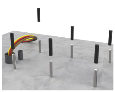
Remove the plastic caps from all mounting bolts on the concrete installation pad.
-
Use a wire brush to clean out threads if any concrete is on the upper bolts.
-
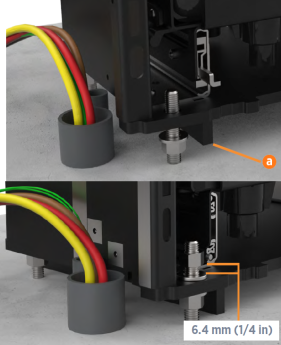
Place a leveling nut and washer on each of the four corner bolts.
-
Leave approximately 6.4 mm (1/4 in) between the bottom of the leveling and the concrete. Check nut positions relative to each other with a level.

THE CRATE IS HEAVY AND CAN CAUSE INJURY OR DEATH IF DROPPED. DO NOT STAND OR WALK BENEATH THE CRATE AS IT IS BEING MOVED. TAKE PRECAUTIONS AGAINST THE CRATE TIPPING OR SLIDING.
-
Retrieve the lifting straps from either the toolkit or the main crate. If there is no separate toolkit: rest the crate in a stable position and unlatch the lid. Retrieve the lifting straps just inside and securely re-fasten the lid.
-
Transport the crate close to the installation site. If using a forklift, position the forklift blades at least
762 mm (30 in) apart to assist with stability. -
If the crate is horizontal:
-
Thread the lifting straps through the 25 mm (1 in) lifting holes in the left and right skids of the crate.
-
Fasten the other ends of the straps to an appropriately-rated forklift or crane.
-
Using the forklift or crane, carefully tilt the crate up until vertical. Use the lifting straps to stabilize the crate and prevent it from tipping.
-
-
Once the crate is vertical, unlatch the lid and set it aside.
-
Remove the wooden braces that secure the Express 250 in the crate.

-
Remove the foam pad from the ceiling of the crate and the foam packaging from the top of the swing arms.
For crane access, or for extra room while forklifting, remove the top screws and top panel of the crate. -
Loosen (but do not remove) the wingnuts holding the boards that secure the charging station base. Slide the support boards away from the charging station.
The Express 250 has a high center of gravity. Take care to prevent tipping when moving the Express 250.
-
Using either a forklift or crane, remove the Express 250 from its crate. Move it to its mounting location and keep it elevated:
-
Using an overhead crane: Thread the supplied lifting straps through the forklift handles, then through the crane lift guides at the top. DO NOT put the straps through the crane lift guides only.
-
Using a forklift: Insert the forklift blades inside the forklift handles. Position the blades approximately 70 cm (27.5 in) apart (inside to inside), and the bottom of the blades approximately 114 cm (45 in) above ground. These measurements vary depending on the type of forklift used.
If a wall is located behind the installation pad, ensure the forklift blades do not protrude far enough to hit the wall when moving the Express 250 onto the pad.To protect the charging connectors from damage, keep them wrapped throughout the installation process. -
Mount and Secure the Express 250
To mount and secure the Express 250, complete the following steps:
-
While the Express 250 is elevated, use a 24 mm (15/16 in) hex wrench to remove the bolts and wooden stands from the bottom of the charging station.
-
Lift the Express 250 over the mounting bolts on the installation pad, ensuring the bolts align with the corresponding holes in the bottom of the Express 250. Move the service wiring out of the way to ensure it is not pinched or trapped.
-
Lower the Express 250 onto the anchor bolts.
-
Install a washer and nut onto each of the four corner mounting bolts to secure the Express 250. For easier leveling, leave a 6.4 mm (1/4 in) gap between the bottom of these top nuts and the baseplate of the frame.
-
Remove the lifting equipment from the installation area.
-
Using a level on all four sides, adjust three of the bottom corner leveling nuts as needed to ensure that the Express 250 is both horizontally and vertically level.
-
When level, tighten leveling top nuts by hand. Then raise the remaining (non-leveling) lower nut by hand-turning until flush against the Express 250’s frame.

-
Tighten the final top nut by hand. Torque all top nuts to 94.9 Nm (70 ft-lbs).
 For easier access to the nuts, press down on the Power Module yellow release latch and slide the tray out.
 -
Using a level, re-check the vertical and horizontal alignment to ensure the tightening of the nuts did not cause the Express 250 to shift. Make any adjustments to ensure the Express 250 is level while all nuts are tightly secured.
-
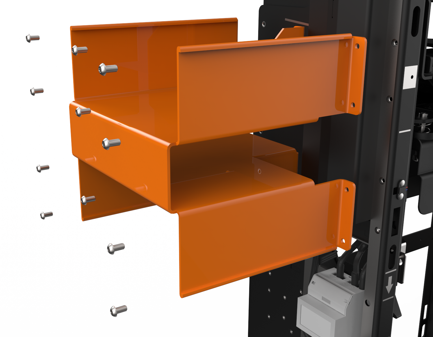
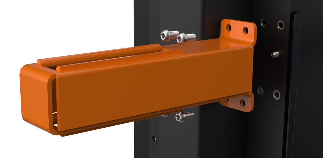
Use the supplied T25 Torx driver to remove the right and left forklift handles from each side of the Express 250.
-
Use the supplied T25 Torx driver and the step ladder to remove the right and left crane lift guides near the top of each side of the Express 250.
-
Remove the HDPE plastic shipping bag from the Express 250 and recycle it.

If you are installing an Express 250 station to be completely surface mounted with above-ground conduit, follow the instructions in the Express 250 Surface Conduit Entry Guide to install the SCE![]() Surface Conduit Entry box base and box cover, then continue with connecting the AC wiring.
Surface Conduit Entry box base and box cover, then continue with connecting the AC wiring.
Connect the AC Wiring
RISK OF SHOCK. Before performing this procedure, disconnect the power to the Express 250 at the service panel. Keep power off for this circuit until all cover panels are correctly reinstalled and the work scope is completed. FAILURE TO FOLLOW THESE INSTRUCTIONS CAN RESULT IN SERIOUS INJURY OR LOSS OF LIFE.
Ensure a grounding conductor that complies with local codes is properly grounded to earth at service equipment or, when supplied by a separate system, at the supply transformer.
To connect the AC wiring, complete the following steps:
-
Follow standard practice and local code to de-energize the applicable circuit and lock out/tag out the disconnect before proceeding. Use a multimeter to test that power is off.
-
If not already done, pull service wiring through the conduit in the installation pad as described in the Express 250 Site Design Guide, available at ChargePoint Product Reference Documentation.
The AC terminal block on the Express 250 can accept up to 35 mm2 (2 AWG
 American Wire Gauge) maximum wire size. If using a larger gauge wire to accommodate a long run, reduce the wire size at the local external disconnect.
 -
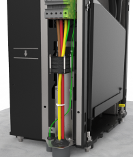
Remove the AC wiring cover on the left side of the Express 250 by pressing on its sides and sliding it downward. Pivot the bottom away from the Express 250 frame.
-
Measure the length needed to extend the wiring from the conduit opening to the Express 250’s terminal block (approximately 61 cm/2 ft). Trim the excess wire.

-
For North America and other regions using conduit:
-
Use a T25 Torx to loosen the two M5 screws attaching the rodent guard bracket to the charging station.
-
Use a T25 Torx to remove the two M5 screws attaching the ferrite mounting to the station.
-
Route the AC wiring bundle through the larger rodent bracket grommet.
-
Route the shunt trip wiring through the smaller rodent bracket grommet.
-
Slide the rodent guard bracket down to leave no gap above the conduit openings. Tighten the T25 screws on the adjustable rodent guard bracket to secure it in place. Multiple screw holes are available to fasten the bracket at different heights.
-
Skip to Strip each wire end 25 mm (1 in)..
Ferrite mounting must be removed from the station prior to routing the AC wiring bundle. Failure to do so may result in wire damage when seating wiring in terminals. Immediately reinstall it once the conductors are in place.
-
-
For the UK and other regions using armored cable:
-
Use a T25 Torx to loosen the two M5 screws attaching the rodent guard bracket to the charging station.
-
Use a T25 Torx to remove the two M5 screws attaching the ferrite mounting to the station.

-
-
Remove the larger grommet in the rodent guard bracket, to avoid interference with the cable gland.
-
Use the smallest cable gland appropriate for the AC conductor size. The bracket can support up to a CW63 size gland.
-
Install the lower cable gland half on the armored cable, below the rodent guard bracket.
-
Route the AC wiring bundle through the rodent guard bracket grommet.
-
Route the shunt trip wiring only through the smaller grommet in the rodent guard bracket.
-
Complete installation of the cable gland. Once secure, tighten the T25 screws on the adjustable rodent guard bracket to secure it in place. Multiple screw holes are available to fasten the bracket at different heights.
-
Bundle the strands of each wire tightly. DO NOT remove strands to fit the wire into the terminal.
-
Connect the L1, L2, L3, and GND
Ground (protective earth) service wiring to the terminal block. Check local code to see if Neutral is needed. Neutral connection is not required for service equipment operation and the terminal is provided for convenience only. To connect each wire:-
Fully insert the Wago tool into the Wago port (a) and rotate the tool firmly counter-clockwise 90o to open the connector.
-
Lock the connector in the open position by firmly pressing the orange button below it (b).
-
Insert the wire fully until it hits the connector’s back stop.
-
Insert and rotate the Wago tool counter-clockwise again to close the connector. The connector clicks as it closes onto the wire and the orange button is released.

Ensure the L1, L2, and L3 cables are installed in the correct order. Incorrect installation creates a phase rotation error later in the process. Phase rotation must be counter-clockwise.
-
-
Inspect the wiring and Wago terminals before proceeding:
-
Ensure no copper is exposed below the terminal.

-
Verify that all strands were fully inserted into the terminal, without being bent back.

-
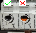
Verify that all Wago connectors are fully closed. A fully closed connector has an orange button in the flush (released) position, and shows no orange in the tool port.

-
Confirm each wire is held securely inside its connector by performing a pull-push test.
Ensure NO copper is exposed below the terminal once installed. -
-
For each of the two shunt trip terminals above the AC terminal block, use a screwdriver to open the locking tab and insert the shunt trip wiring from the smaller conduit. (Only one wire is shown in the example.) Shunt wires are interchangeable. Release the terminal tab and confirm each wire is held securely by performing a pull-push test.
-
Use cable ties to bundle the wires in one or two places.
-
Use the supplied duct seal compound to completely seal all AC openings against pest ingress:
-
The inside of the conduit opening
-
Within the rodent guard bracket openings for wiring
-
Around the edges of the rodent guard bracket where it will meet the extrusion
-
-
Install the AC wiring cover:
-
Tilt the narrow end of the cover under the side panel.
-
Slide the tabs near the bottom of the cover into the slots on the Express 250. Squeeze the sides of the wiring cover as you guide these tabs into the slots.
-
Slide the wiring cover upward until the tabs click into place.

-
Installing the rodent guard brackets as described below protects the system against pest ingress from under the station or along the wiring. Pest ingress in AC and DC terminal areas can damage the system and/or result in system downtime. Rodent guard bracket installation is required.
Ferrite mounting must be removed from the station prior to routing the AC wiring bundle. Failure to do so may result in wire damage when seating wiring in terminals. Immediately reinstall it once the conductors are in place.
Stripping the wire less than 25 mm (1 in) can prevent the Wago port from adequately securing the wire. This can cause arcing or a similar electrical hazard that could result in property damage, injury, or death.

Ensure the exposed wires are tightly bundled with no loose strands. Loose or missing strands can cause arcing or a similar electrical hazard that could result in property damage, injury, or death.
The conduit opening must be sealed to protect the wiring from the environment.
