Express 250
ChargePoint® Networked Charging Station
Advanced FRU Guide: Repairing Hall Sensors
RISK OF SHOCK. Some stations share DC power (paired configuration). Pairing should be marked on the AC disconnect or breaker panel. Before performing this procedure, check for pairing and, if present, disconnect the power to BOTH stations at the service panel. Whether Standalone or Paired, follow standard practice and local code to de-energize the applicable circuit and lock out/tag out the disconnect before proceeding. Use a multimeter to test that power is off. Keep power off for this circuit until all cover panels are correctly reinstalled and the work scope is completed. FAILURE TO FOLLOW THESE INSTRUCTIONS CAN RESULT IN SERIOUS INJURY OR LOSS OF LIFE.
- If the charging station is not installed, commissioned, or serviced by a ChargePoint certified technician using a ChargePoint-approved method, it is excluded from all ChargePoint and other warranties and ChargePoint is not responsible.
- You must be a licensed electrician and complete training at https://www.chargepoint.com/partners/training-certification to become ChargePoint certified and to access ChargePoint's web-based installer tools or ChargePoint Installer app.
Do not discard the part you are replacing. Use the new Field Replaceable Unit (FRU Field Replaceable Unit) packaging to return all removed parts to ChargePoint.
For assistance, go to chargepoint.com/support and contact technical support using the appropriate region-specific number.
Required Tools and Materials
|
|
Head lamp |
|
Stepladder |
|
|
Torx screwdriver (T10, T20) |
|
T25 Security screwdriver |
|
|
Wire cutter |
|
Gloves |
|
|
|
|
|







-
ChargePoint FRU
Field Replaceable Unit kit, Hall sensors:-
Hall sensor, magnetic south pole (x2)
-
Insulation displacement connectors (x4)
-
Extra black nylon barbed mounting rivets
-
Extra wire
-
This repair takes one technician about 1-2 hours to complete.
About Panels

All panels have guide tabs that align with corresponding slots on the product’s frame. When removing a panel, lift the panel upward to release these tabs from their slots.
Panels overlap from the bottom to the top. To remove any panel, all panels above it on that side must be removed first.
Diagnose Broken Sensor Location(s)
-
Before powering off the station, note which panel errors are displayed on the touchscreen. The station uses Hall sensors to detect correct installation of all cover panels. An automatic system test checks all Hall sensors, to prevent water ingress or shock risk from touching internal components.
-
Ensure all panels are fully installed and seated, to rule out panel misalignment as the error reason.
-
Power on the station and check the lower right corner of the touchscreen for error messages. If panel errors still appear, match the panel letters on the left illustration to sensor locations on the right:
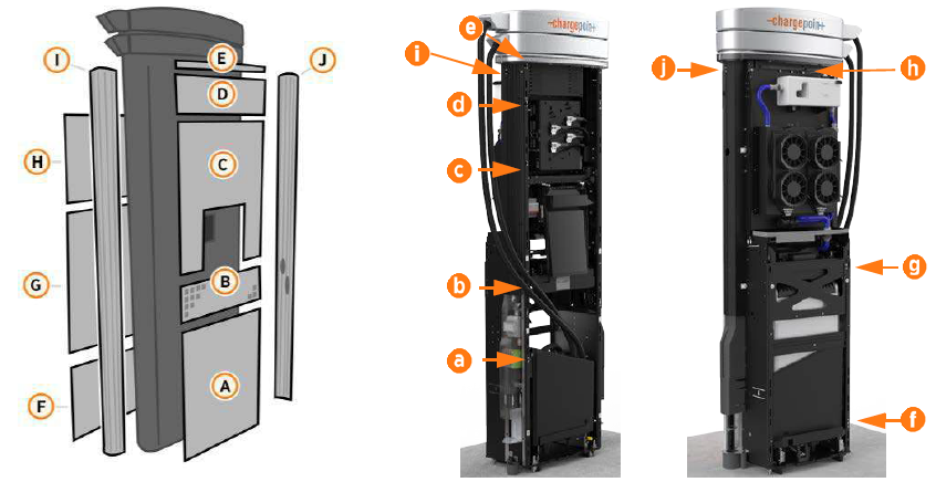
Error
Associated Panel
Remove These Panels for Sensor Access
a
Front bottom panel
A-E
b
Middle vent panel
B-E
c
Front top panel
C-E
d
Secondary display
D-E
e
Area light bar
E
f
Rear bottom panel
F-H
g
Rear middle panel
G-H
h
Rear top panel
H
i
Left extrusion
A-I
j
Right extrusion
A-H, J
Power off at the breaker panel and lock out/tag out before continuing work.
RISK OF SHOCK. Before performing this procedure, disconnect the power to the station at the service panel. Keep power off for this circuit until all cover panels are correctly reinstalled and the work scope is completed. FAILURE TO FOLLOW THESE INSTRUCTIONS CAN RESULT IN SERIOUS INJURY OR LOSS OF LIFE.
If additional access to wiring is needed, remove the nearest side extrusion as well. Removing either extrusion requires removing all front and rear panels first.
Power Off the Station
Power off at the breaker panel and lock out/tag out before continuing work.
RISK OF SHOCK. Before performing this procedure, disconnect the power to the station at the service panel. Keep power off for this circuit until all cover panels are correctly reinstalled and the work scope is completed. FAILURE TO FOLLOW THESE INSTRUCTIONS CAN RESULT IN SERIOUS INJURY OR LOSS OF LIFE.
Remove Cover Panels for Access
According to the table above, use these procedures to remove only as many cover panels as are needed to access the broken sensor:
Once all required panels are removed, proceed to Replace the Hall Sensor.
Remove the Area Light Bar
-
Using a T25 Security screwdriver, loosen the two captive screws on the area light bar.

-
Disconnect the power cable that connects the area light bar to the LED display assembly. Remove the area light bar.
When reinstalling, ensure the gasket on each end of the area light bar is properly seated around the plastic tab.
Remove the LED Display
-
Push the LED display upward to release its guide tabs from their corresponding slots on the Express 250’s frame.

-
When the LED display assembly is released, disconnect the five cables from the back.
When reinstalling, connect the five cables to their corresponding connectors on the back of the display. Leave the area light bar cable (e) loose.
(a) Communications cable (USB
Universal Serial Bus-A)(b) Holster light cable
(c) Area light cable x 2 (interchangeable)
(d) Power cable (24 V)
Do not allow the LED display to hang from its cables.
Remove the Top Front Panel

-
Using two hands, pull the top panel upward to release its guide tabs from their corresponding slots on the Express 250’s frame.
-
Place a protective cover, such as a lint-free cloth, over the touchscreen to prevent damage during service.
When reinstalling, push the bottom edge inward to position it inside the groove in the middle vent panel and engage the edge of the sign. Carefully push the panel down until it is firmly seated.
When reinstalling, ensure all five cables at the top of the panel are not captured by the front upper panel, and are easily accessible for reinstalling the LED display.
Remove the Middle Vent Panel
-
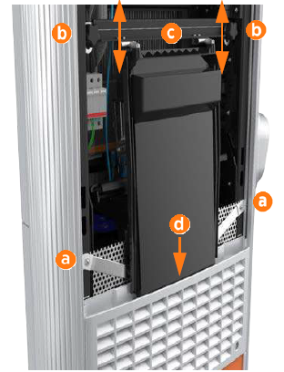
Use a T25 Torx driver to remove the M5 screw and washer (a) attaching each touchscreen ground strap to the frame. Keep the screws and washers for reuse.
-
Loosen both retention knobs (b), allowing the touchscreen beam (c) to slide up vertically and the touchscreen’s bottom edge to clear the middle vent panel’s slot (d).
-
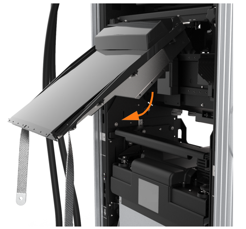
With hand pressure, tilt the touchscreen upward at a 45-degree angle.
-
Allow the touchscreen to return to its lowest position vertically. Rotate the retention knobs clockwise to re-tighten.
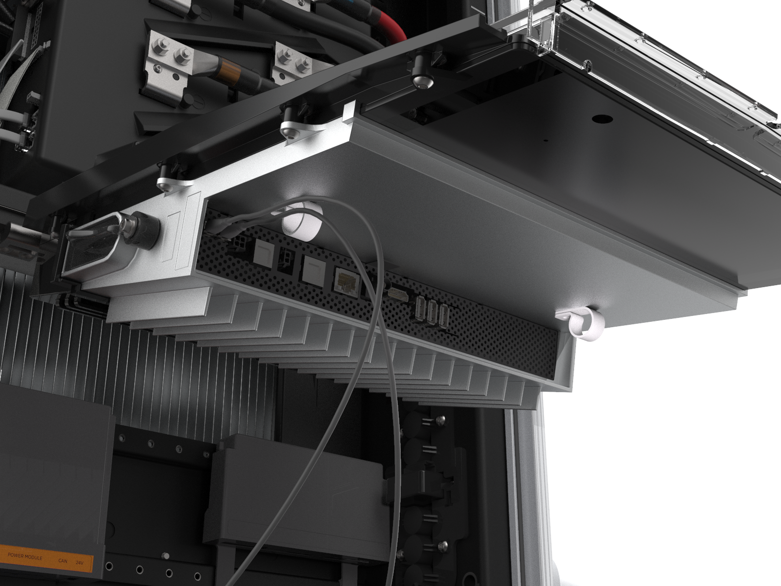
The bottom edge and corners of the touchscreen are sharp. Take care when moving underneath the raised screen. - Disconnect all cables from the connectors on the bottom of the touchscreen and remove them from the wire management rings.
-
Loosen both retention knobs enough to remove the touchscreen completely from the station. Carefully set it aside in a safe place for reinstallation.
-
Using two hands, one on each side of the middle vent panel, remove the panel by firmly pulling it upward to release the guide tabs from the corresponding slots on the Express 250’s frame.

The fins on the back surface of the middle vent panel are sharp. Take care when handling the panel.
Remove the Bottom Front Panel
Remove the bottom front panel by lifting upward from the bottom of the panel to release the guide tabs from their corresponding slots on the Express 250’s frame.

Remove Top Rear Panel
-
Using a T25 Torx (or a Phillips #2 screwdriver for early charging stations), loosen the two hidden captive screws located in the top rear panel’s vents, inset from each bottom corner.

-
Using a T25 Torx driver, loosen the two captive screws located at the top of the top rear panel. Using two hands, hold the top rear cover at an angle to remove, leading with the bottom edge.
When reinstalling, squeeze the sides of the panel inward to fit the tabs into place in the C-channel, inside the watertight gasket.
Remove Middle Rear Panel
Using two hands, lift the middle rear panel straight up and out to disengage the guide tabs.

Small gauge wiring routed on the sides of the frame could be sheared if caught by panel tabs. Ensure wiring is cleared from guide holes when installing bottom and middle rear panels.
Remove the Bottom Rear Panel
Using two hands, carefully pull the panel upward to release the panel’s guide tabs from their corresponding slots on the product’s frame.

Open the Power Module Holders (Ground Straps)
If more room is needed to access the Hall sensor or remove side extrusions, remove grounding protections and open the Power Module holders. This procedure is optional.
Electromagnetic Interference shields instead of ground straps, refer to Open the Power Module Holders (EMI Shields) instead.
-
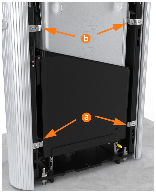
Use a T25 Torx to remove the front and rear M5 screws and washers attaching the Power Module holder (a) and Power Module(b) ground straps to the Express 250 frame (eight screws total). Keep the screws and washers for use in a later step.
-
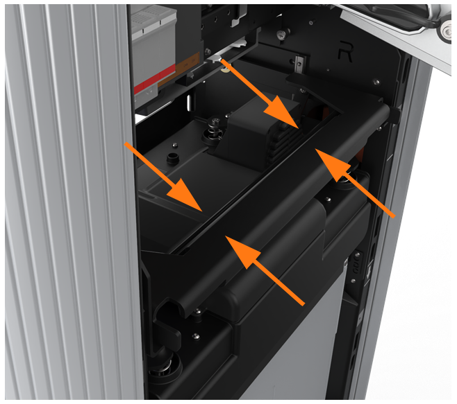
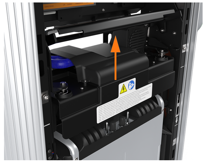
Using two hands, squeeze the Power Module mechanism’s release bar against the flange. Raise the bar to fully rotate the Power Module mechanism upward to the lock position. This ensures enough clearance for the Power Modules to slide under the mechanism.
-
At the bottom right of the Express 250, press and hold the yellow release latch while pulling the Power Module tray out of the station completely.

Open the Power Module Holders (EMI Shields)
If more room is needed to access the Hall sensor or remove side extrusions, remove grounding protections and open the Power Module holders. This procedure is optional.
Electromagnetic Interference shields, refer to Open the Power Module Holders (Ground Straps) instead.
-
Use a T20 Torx to remove the top two screws and washers from the rear EMI
Electromagnetic Interference shield (a).
-
Use a T25 Torx to remove the four middle and lower screws and washers from the rear EMI
Electromagnetic Interference shield (b). The rear shield might be in one or two sections. Save all screws and washers for later reuse.When reinstalling, ensure:The cutout on the long edge is on the right side (c), leaving the sensor wire clear.
The drain hose and cooling controller cover flap are inside the EMI
Electromagnetic Interference shield.
-
Use a T25 Torx to remove the six T25 screws and washers from the front EMI
Electromagnetic Interference shield (d). When reinstalling, position the bottom cut-out over the yellow release latch (e).
 -
Using two hands, squeeze the Power Module mechanism’s release bar against the flange. Raise the bar to fully rotate the Power Module mechanism upward to the lock position. This ensures enough clearance for the Power Modules to slide under the mechanism.
-
At the bottom right of the Express 250, press and hold the yellow release latch while pulling the Power Module tray out of the station completely.
Remove the Right Extrusion
-
Remove the charging cables from their holsters and rest them gently on a padded surface out of the way.
-
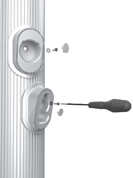
Insert a small flathead screwdriver into the notch on each plastic cap to remove it from the holster screw opening.
-
Use a T25 Torx to remove the rubberized washer and M5 shoulder screw. Set them aside for reuse.
-
Using one hand, hold the extrusion and loosen the top two captive screws using the supplied T25 Torx driver. (The blue Ethernet wire in the image might or might not be installed depending on the site. It does not affect this procedure.)
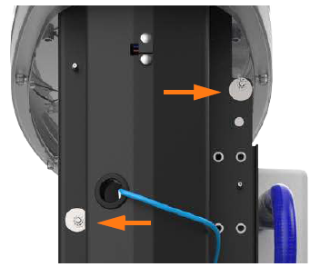
Use a step ladder to reach the top screws.
The top screws are asymmetrical. -
Use a T25 Torx driver to loosen the middle two screws, just above the Power Module mechanism.
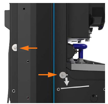
Access to the middle screws is easier with the Power Module mechanism handle in the closed (down) position.
-
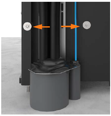
Loosen the bottom two captive screws on the extrusion. (Cables might or might not be installed depending on the site. It does not affect this procedure.)
-
Slightly tilt the bottom of the extrusion out to extract its top edge from under the bottom edge of the area light bar. Lift the extrusion off the guide pins on each side of the frame that hold the extrusion in place.
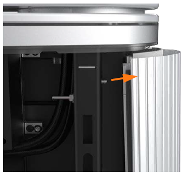
Keep the extrusion close to the station until its cables are disconnected.
-
Disconnect the shortest cable from the top holster.

-
Disconnect the next-longest cable from the bottom holster.
If there is a third, longer cable, bundle it to avoid pinch points during installation. The third cable is not currently used.
When reinstalling, check that these connections are correctly seated, or the system will not operate.
-
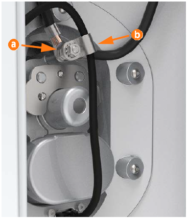
Depending on the generation of holster, use either a T25 Torx driver or an 8 mm nut driver to remove the P-clip hardware stack (a) from the lower holster of the extrusion.
Carefully note the order of the components.
-
Remove the shielded holster cable from the opening in the P-clip (b).
-
Remove the extrusion from the station. Lay it aside on a padded surface for reuse.
Remove the Left Extrusion
-
Using one hand, hold the extrusion and loosen the top two captive screws using the supplied T25 Torx driver. (The blue Ethernet wire in the image might or might not be installed depending on the site. It does not affect this procedure.)
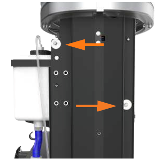
Use a step ladder to reach the top screws.
The top screws are asymmetrical.
-
Use a T25 Torx driver to loosen the middle two screws, just above the Power Module mechanism.
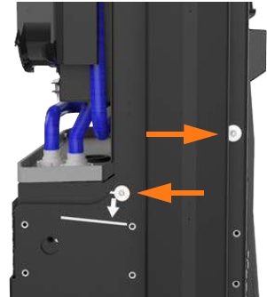
Access to the middle screws is easier with the
Power Module mechanism handle in the closed (down) position.
-
Loosen the bottom two captive screws on the extrusion.
(Cables might or might not be installed depending on the site. It does not affect this procedure.)
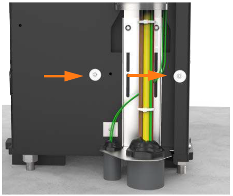
-
Slightly tilt the bottom of the extrusion out to extract its top edge from under the bottom edge of the area light bar. Lift the extrusion off the guide pins on each side of the frame that hold the extrusion in place.
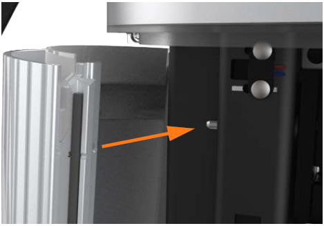
Replace the Hall Sensor
-
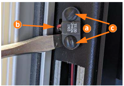
Inspect the Hall sensor (a) for the location of the wire damage.
-
Note which direction the sensor wires (b) are oriented, for later reinstallation.
-
Use a screwdriver to pry out the two barbed rivets (c) holding the sensor to the metal frame.
-
Gently pull the wire farther out of the frame. Some service loop exists in the wiring harness to allow room for repair. If needed, cut off the nearest wiring zip tie for better access.
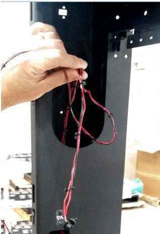
-
Cleanly cut the old sensor and rivets off the wiring harness and discard them.
-
Trim the new sensor’s wires to length, allowing working room but not allowing excess wire to get caught by cover panels.
You must cut or pull off any labels on the wiring. The
connector does not cut through labels.
-
Slide the new red wire and station red wire side by side into the displacement connector. The wires do not have to be stripped. Look through the clear plastic on the bottom to ensure both wires are fully seated.
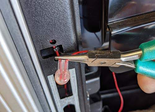
-
Use pliers to press the connector’s button completely closed.
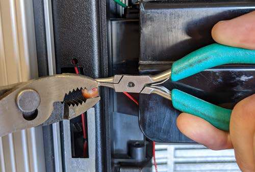
-
Ensure the button is now flush with the housing. Some dielectric grease might be squeezed out as the button is pressed. If so, clean it away.
-
Check the back of the connector to ensure that both wires are still fully seated (d) and did not move when the connector closed (e). If either wire is outside the terminal area, cut off the connector and repeat with a new one.
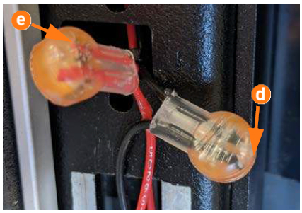
-
Repeat the above steps for the two black wires.
Twisting the sensor’s red and black wires loosely together before installation can help prevent the wires from catching on other components.
-
Carefully feed the wiring harness back into the frame. Route and straighten it so that it cannot get caught by cover panels when they hook onto the frame openings in a later step.
-
Use two new barbed rivets from the kit to secure the new sensor onto the frame in the correct location.
REVERSE THE ABOVE STEPS TO REPLACE ALL REMOVED COMPONENTS: SIDE EXTRUSIONS, POWER MODULE HOLDERS, GROUND STRAPS OR EMI Electromagnetic Interference SHIELDS, REAR PANELS, FRONT PANELS, LED DISPLAY, AND AREA LIGHT BAR.
Power On the Station
Once all cover panels are installed, power on the station. The on-screen Installation Wizard steps you through any required tasks to set up the station and verify that it can operate properly.
An Installation Wizard test checks that all cover panels are correctly installed and fully seated. Check the lower right corner of the screen for any error messages. If panel errors appear, match the panel letters to this illustration.
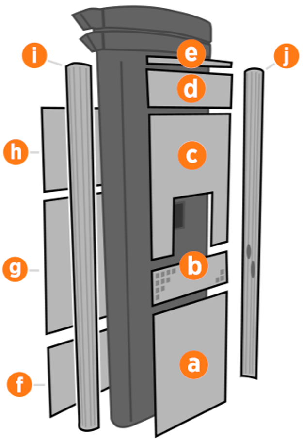
(a) Front bottom panel
(b) Middle vent panel
(c) Front top panel
(d) LED display
(e) Area light bar
(f) Rear bottom panel
(g) Rear middle panel
(h) Rear top panel
(i) Left extrusion
(j) Right extrusion
If any panel needs re-installation, review the procedures above to double-check that all panels are fully seated and that the edges of all signs are captured fully by the panels around them.
