Install Cover Panels
This topic describes how to correctly attach all cover panels. This is required to prevent any electrical shock hazard before powering on the charging station. These steps below are relevant for both Standalone and Paired installations.
To install cover panel, complete the following steps.
Power off the Station
Power off at the breaker panel and lock out/tag out before continuing work.
RISK OF SHOCK. Before performing this procedure, disconnect the power to the station at the service panel. Keep power off for this circuit until all cover panels are correctly reinstalled and the work scope is completed. FAILURE TO FOLLOW THESE INSTRUCTIONS CAN RESULT IN SERIOUS INJURY OR LOSS OF LIFE.
Open the Power Module Tray
Follow the below steps to open the Power Module Tray:
-
Using two hands, squeeze the Power Module mechanism’s release bar against the flange. Raise the bar to fully rotate the Power Module mechanism upward to the lock position.
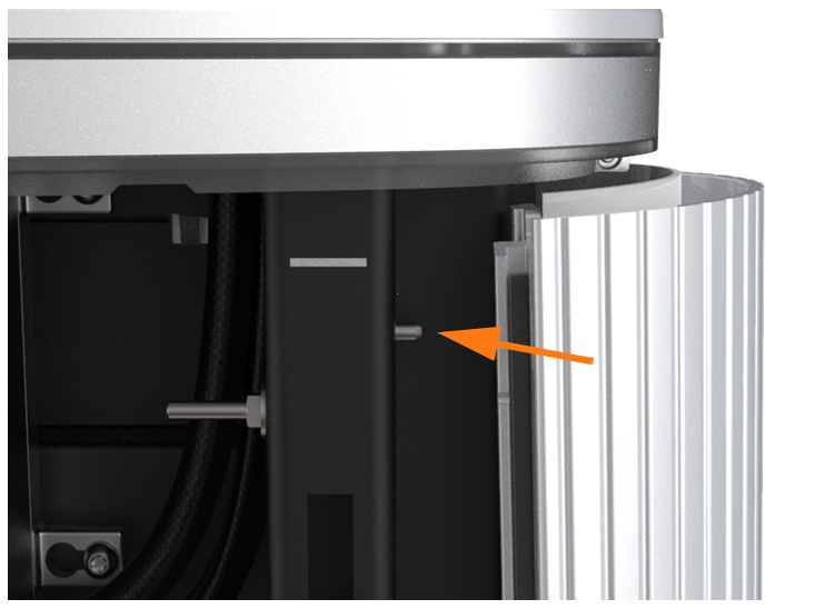
-
At the bottom right of the Express 250, press and hold the yellow release latch while pulling the Power Module tray out of the station completely.

-
Carefully lift the charging cables/connectors out of the Power Module tray and rest them gently on a padded surface out of the way.
Install the Left Extrusion
Follow the below steps to install the Left Extrusion:
-
Slightly tilt the left extrusion and slide its top edge under the bottom edge of the area light bar. Align the holes in the extrusion with the guide pins on each side of the frame.

-
Using a step ladder, hold the extrusion and loosely secure the top two captive screws with a T25 Torx driver.


-
Use a T25 Torx driver to loosely secure the bottom two screws while the Power Module mechanism is in the closed (down) position.

-
Use a T25 Torx driver to loosely secure the middle two screws, just above the Power Module mechanism.

-
Tighten all left extrusion screws.
Connect the Right Extrusion’s Holster Light Cables
Follow the below steps to connect the Right Extrusion's cables:
-
Locate the P-clip mounted to one of the holsters (top or bottom holster varies by product version).

-
Remove the P-clip hardware from the extrusion holster:
-
Generation 1, attached with screw: use a T25 Torx driver to remove the screw and all its components. Carefully note the order of the components.
-
Generation 2, attached with nut (shown): Use an 8 mm nut driver to remove only the nut and the P-clip.
-
-
Identify the holster light cable hanging from the right side of the dispenser.
-
Insert the shielded holster cable into the opening in the P-clip to complete the ground path.
-
Connect the shortest cable to the top holster.
-
Connect the next-longest cable to the bottom holster.
 If there is a third, longer cable, bundle it to avoid pinch points during installation. The third cable is not currently used.
Check that these connections are correctly seated, or the system will not operate.
-
Reinstall the P-clip hardware stack:
-
Generation 1: holster, star washer, ground cable lug, P-clip with light power cable routed through, M5 T25 screw head.
-
Generation 2: holster stud, P-clip with light power cable routed through, nut. Torque the nut to 5.5 Nm (48.7 in-lb).
-
Install the Right Extrusion
Follow the below steps to install the Right Extrusion:
-
Slightly tilt the right extrusion and slide its top edge under the bottom edge of the area light bar. Align the holes in the extrusion with the guide pins on each side of the Express 250’s frame.
-
Using a step ladder, hold the extrusion and loosely secure the top two captive screws using a T25 Torx driver.


-
Use a T25 Torx driver to loosely secure the bottom two screws next. The Power Module holders must not be inside the charging station to have access to the bottom screws.

-
Use a Torx driver to loosely secure the middle two screws, just above the Power Module mechanism.

-
Tighten all right extrusion screws.

-
Secure each holster to the frame using a T25 Torx to fasten a supplied rubberized washer and M5 shoulder screw.
-
Align a supplied plastic cap over each holster opening and snap it into place.
Install the Power Modules
Follow the below steps to install the Power Modules:
-
Tilt both Power Module holders down to the ground and rest them on their kickstands.
-
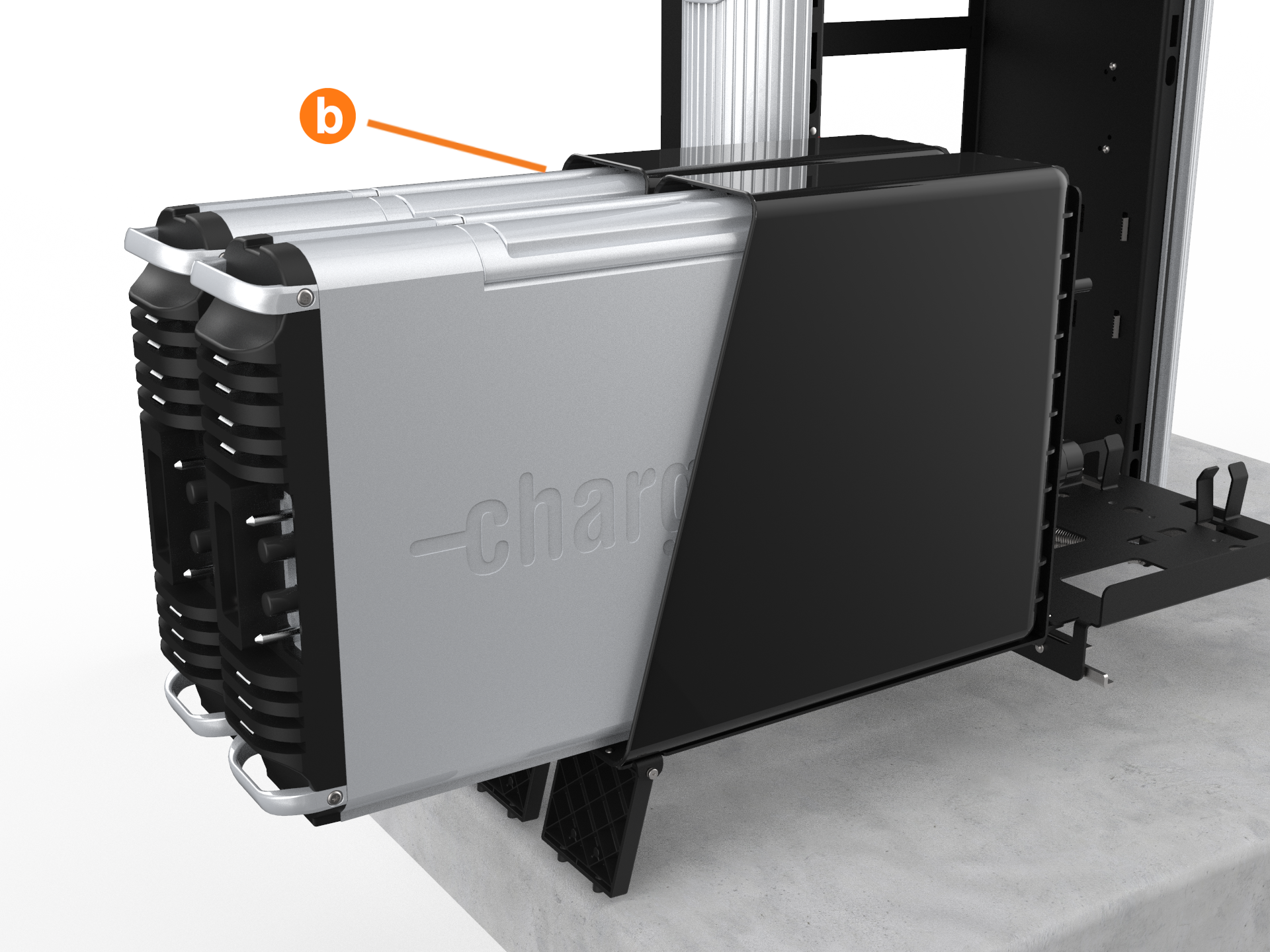
Install the rear Power Module first. Using two people, lift the Power Module by its top handles and gently slide it into its holder with its connections facing outward (a).
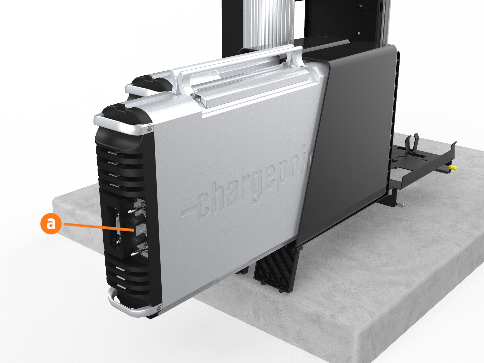
-
Once the Power Module is positioned partially inside its holder, fold the handles down to slide it in completely.
-
Repeat the step for the second Power Module if applicable.
-
Lift each Power Module to the upright position one at a time.
-
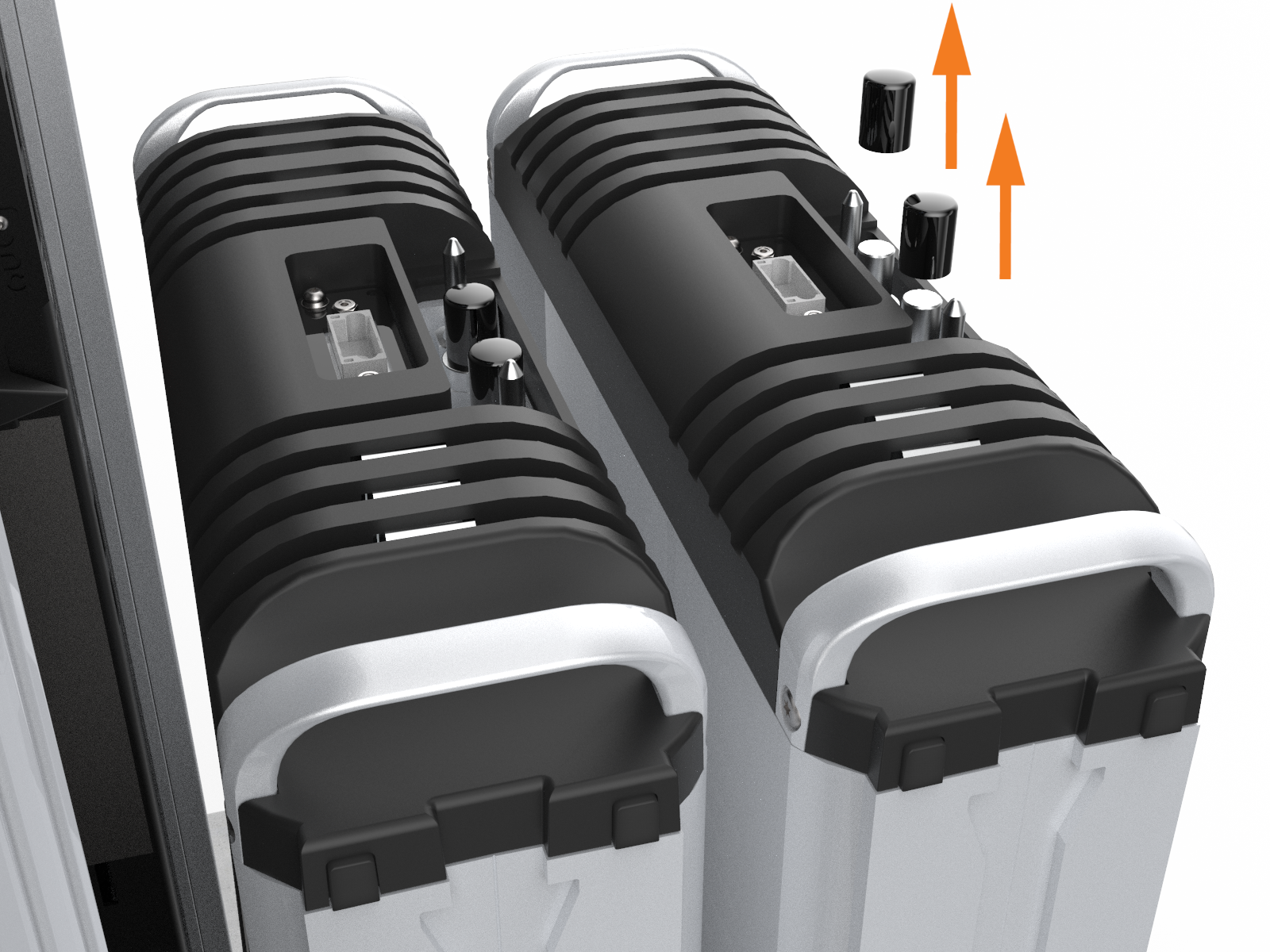
If not already done, remove the safety caps from the coolant ports.
-
At the bottom right of the Express 250, press and hold the yellow release latch while pushing the Power Module tray into the station until it locks into place.

-
Using two hands, squeeze the Power Module mechanism’s release bar and lower it halfway to check alignment with the ports and guide posts.
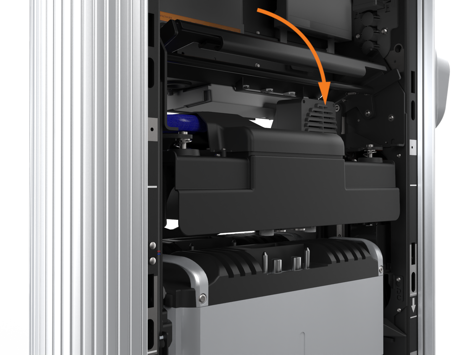
-
Lower the Power Module mechanism until you hear a click as the mechanism locks into place. Ensure the mechanism is fully engaged with all Power Module connectors. The Power Module mechanism should fully cover the ridges on the Power Module’s top edge.

Install the EMI Shields
Follow the below steps to install the EMI![]() Electromagnetic Interference shields:
Electromagnetic Interference shields:
The EMI![]() Electromagnetic Interference shields do not need to be installed and you do not need the grounding straps if the station has two Power Module 1.5 versions.
Electromagnetic Interference shields do not need to be installed and you do not need the grounding straps if the station has two Power Module 1.5 versions.
-
Identify the places on the front and back of the frame that show silver grounding locations instead of the normal black of the frame.
The metal EMI![]() Electromagnetic Interference shield edges can be sharp. Take care when moving and installing the shields.;
Electromagnetic Interference shield edges can be sharp. Take care when moving and installing the shields.;
-
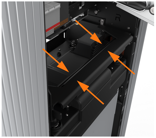
Position the rear EMI
 Electromagnetic Interference shield (a) over the closed Power Module holder, the drain hose, and the cooling controller cover (b). Ensure the cutout on the long edge is on the right side, leaving the sensor wire clear.
-
Remove the two T20 screws (c) that align with the top EMI
Electromagnetic Interference shield tabs. Discard the star washers beneath them, if present. -
Use isopropyl wipes to clean the frame grounding locations and both sides of the rear EMI
Electromagnetic Interference shield tabs. -
Reinstall the T20 screws with an M5 flat washer from the installation kit to secure the top tabs of the shield on each side.
-
Use a T25 Torx, an M5 screw, and an M5 washer to attach the rear EMI
Electromagnetic Interference shield to each middle and bottom grounding location on the rear of the frame (d). Torque to 4 Nm (35 in-lb). -
Use isopropyl wipes to clean the frame grounding locations and both sides of front EMI
Electromagnetic Interference shield tabs. -
Remove the two T25 screws and washers that align with the top front EMI
Electromagnetic Interference shield tabs (g). -
Position the front EMI
Electromagnetic Interference shield (e) over the closed Power Module holder, ensuring the bottom cut-out is positioned over the yellow release latch (f). -
Reinstall the T25 screws and washer to secure the top tabs of the shield (g) on each side.
-
Use a T25 Torx, an M5 screw, and an M5 washer to attach the front EMI
Electromagnetic Interference shield to each middle and bottom grounding location on the front of the frame (h). Torque to 4 Nm (35 in-lb).
Fill the Coolant Reservoir
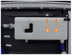
The Express 250 is shipped with an empty coolant reservoir. Coolant and a funnel are included with the product. Most coolant lines are already connected to the reservoir with quick connect fittings, except the ones shown below.
Always fill the coolant reservoir after installing the Power Modules in the station mechanism, since Power Modules are part of the coolant path. Filling the reservoir first does not allow full station coolant levels.
-
Attach the quick connect line on the right side of the coolant reservoir. The line audibly clicks when connected.

-
Attach the quick connect line on the left side of the coolant reservoir.

-
Using a step ladder if needed, unscrew the reservoir fill cap (a).
-
Use a funnel to fill the reservoir to the marked MAX line with coolant.

-
Replace the reservoir cap.
-
Use the cloth to wipe up any coolant spills.
-
Cut and remove the three zip ties that secure the fan trays during shipment.

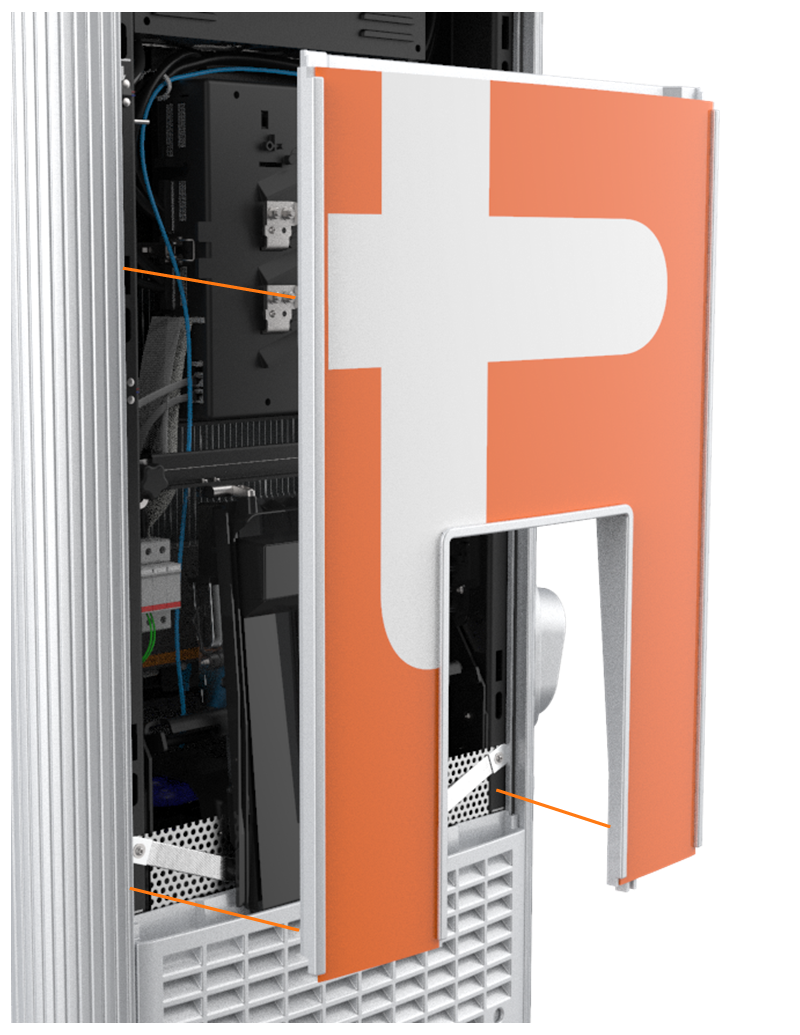
Install the Rear Cover Panels
All Express 250 panels have guide tabs that align with corresponding slots on the Express 250’s frame. When removing a panel, lift the panel upward to release these tabs from their slots. When installing a panel, align these tabs above their corresponding slots and press the panel downward.

When installing the rear panels, take special care to ensure that each panel is correctly positioned. Failure to do so can prevent station operation.
Small gauge wiring routed on the sides of the frame could be sheared if caught by panel tabs. Ensure wiring is cleared from guide holes when installing bottom and middle rear panels.
-
Using two hands, align the guide tabs on the lower rear panel to the matching slots on the Express 250. Squeeze the sides of the panel inward to fit the tabs into place in the C-channel, inside the watertight gasket. Carefully push the panel down until the bottom edge aligns with the bottoms of the side extrusions.


The charging station has guide marks on the frame, to show initial and final cover locations.
-
Using two hands, align the guide tabs on the panel to the matching slots on the enclosure frame. Squeeze the sides of the panel inward to fit the tabs into place in the C-channel, inside the watertight gasket. Carefully push the panel down until the bottom edge aligns with the bottoms of the side extrusions.


-
Using two hands, hold the top rear panel at an angle and slide into place beginning with the top edge. Squeeze the sides of the panel inward to fit the tabs into place in the C-channel, inside the watertight gasket.
-
Use a T25 Torx driver to loosely secure the top of the top rear panel to the enclosure frame with the two screws.

-
Use a T25 Torx driver to tighten the two hidden captive screws located in the rear panel's vents, inset from each bottom corner.
-
Use the T25 Torx driver to tighten the top two screws.

Install the Front Cover Panels
Follow the below steps to install the Front Cover Panels:
-
Align the guide tabs on the front bottom panel to the matching slots on the Express 250’s frame. Push the panel down carefully until the bottom edge aligns with the bottoms of the side extrusions.

-
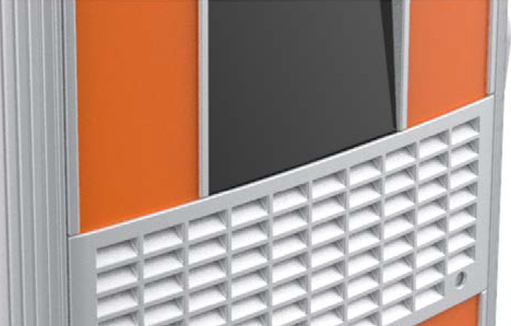
Align the guide tabs on the middle vent panel to the corresponding slots on the Express 250’s frame. Ensure the lower sign is correctly captured as you carefully push the middle panel down until it is fully seated.

-
Remove the packaging tape and material from the touchscreen.
The fins on the back surface of the middle vent panel are sharp. Take care when handling the panel.
-
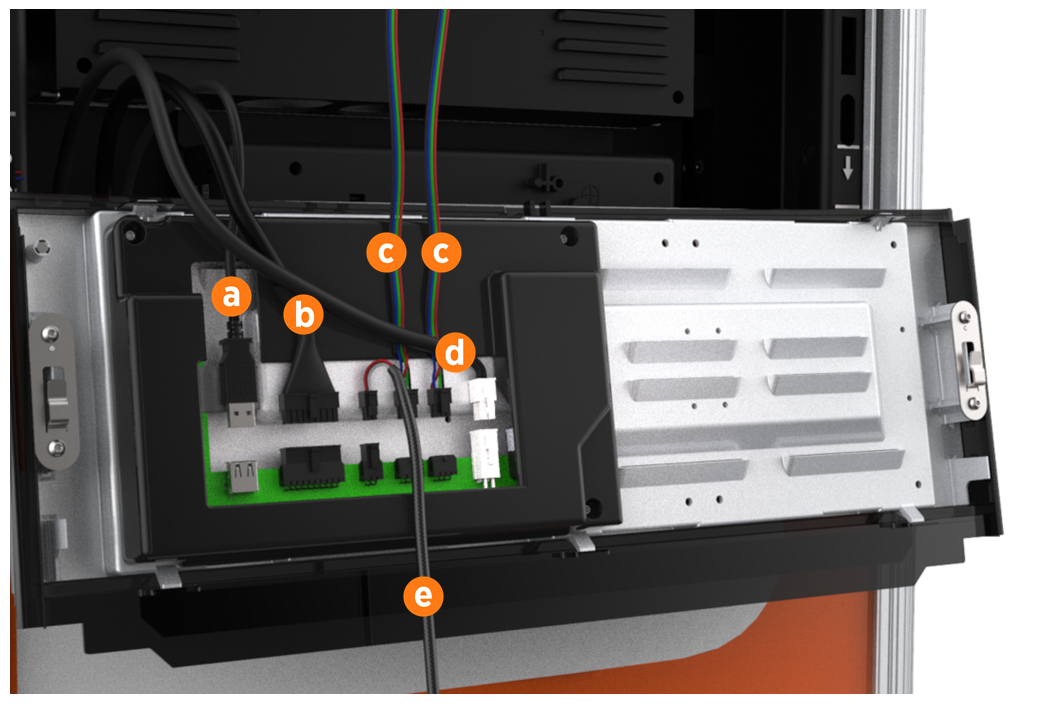
Connect the proximity sensor wires on the middle vent panel to the corresponding connectors on the bottom of the touchscreen: left wire to left port and right wire to right port.
-
Route any excess wiring through the wire management rings under the touchscreen, to prevent it being pinched in the panels.
-
With hand pressure, swing the touchscreen down. Loosen both retention knobs (a), allowing the touchscreen beam (b) to slide up vertically. Re-tighten the knobs at the highest position.

-
Tilt the bottom of the touchscreen inside the slot in the middle vent panel, aligning the notch in the center of the bottom edge (c) to the guide ridge inside the panel slot.
-
Keeping pressure on the edge of the touchscreen to properly seat it inside the panel, loosen the knobs to lower the screen again. Re-tighten the knobs to secure it.
-
Use a T25 Torx driver, an M5 screw, and an M5 washer to attach each end of the touchscreen ground strap to the frame (d). Torque to 4 Nm (35 in-lb).
-
Using two hands, align the guide tabs on the front upper panel with the corresponding slots. While pushing the panel into place, push the bottom edge and its sign inward to position them inside the groove in the middle vent panel and engage the edge of the sign.
-
Carefully push the panel down until it is firmly seated.
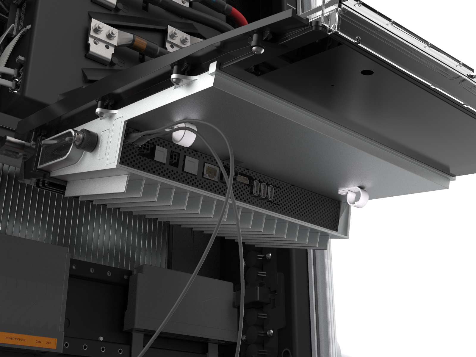
Ensure all five communication cables at the top of the Express 250 are not captured by this front upper panel, and are easily accessible.
Install the LED Display and Area Light Bar
-
Unpack the LED display from its shipping box. While holding the LED display near the opening at the top of the Express 250, connect its five cables to their corresponding connectors on the back of the display (each connector is keyed to fit only into its matching port):
-
Communications cable (USB
Universal Serial Bus-A) -
Holster light cable
-
Area light cable (x2)
-
Power cable (24 V)
-
Leave the area light bar cable (e) loose.
-
Angle the top edge of the LED display under the light bar on the Express 250. Starting at the top, align and slide the LED display guide tabs into the corresponding slots. Ensure the lower sign is correctly captured by the bottom edge of the LED display. Push the bottom into place until firmly seated.

-
Connect the power cable from the LED display to the area light bar.
-
Position the area light bar above the LED display with the lights facing downward. Align the area light bar and hold it in place with enough force to compress the gaskets.
-
Ensure the gasket on each end of the new area light bar is properly seated around the plastic tab.

-
Use a T25 Torx driver to tighten the two captive screws on the bottom edge of the area light bar.

-
Unwrap the charging cable connectors and insert each connector into its corresponding holster.
-
Remove the protective tape from the swing arms, signs, and touchscreen.
-
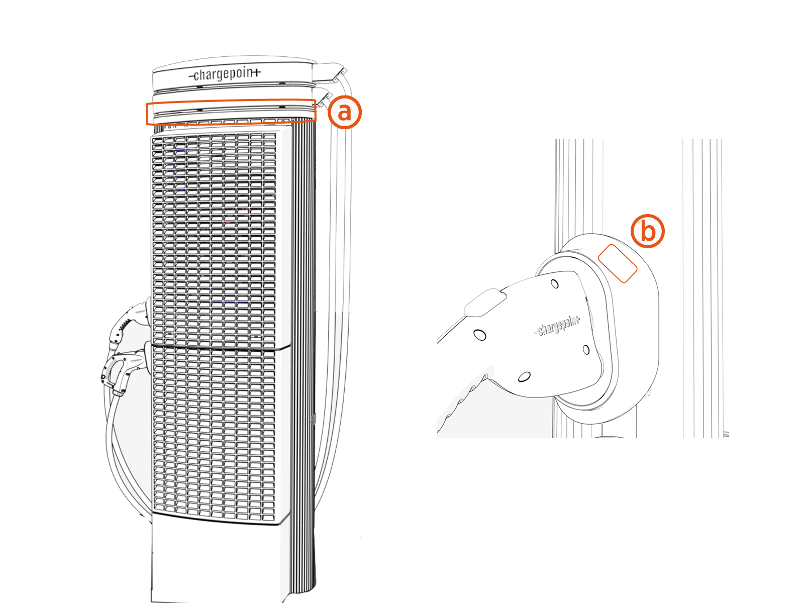
Ensure the rating markings are visible above the light ring, located on the plastic just below the swing arm in the rear of the charging station. (The CE label is just below the swing arm on the left side of the charging station.)
You have now completed the physical installation of the Express 250. Follow the steps in the next section to complete the installation. Do not leave the installation site until you complete all steps in the next section and verify the Express 250 is operating correctly.
Installing Rating Labels for Power Select (Optional)
If the Express 250 is installed with a maximum capacity less than 62.5 kW, apply this ratings label below the cable swing arms (a) in the back and to the holster (b) of the station.