PD Controller Troubleshooting
This section is aimed to help Industrial Support Engineers, field technicians, and the Commissioning team in identifying problems and performing initial debug of problems related to the PD Controller.
Open PD Controller
-
Quarter turn the door latch to unlock the door.

-
Open the door.

Close PD Controller
Close the PD Controller and quarter turn the door latch.

PD Controller Components
This section covers the PD Controller components.
Power and Protection Components
.png)
|
Symbol |
Component Type |
Color |
Description |
|---|---|---|---|
|
CB1 |
Circuit Breaker |
WHITE |
Circuit breaker and field landing for AC power (L/N) |
|
PS1 |
Power Supply |
SILVER |
24 V system power supply |
|
PS2 |
Power Supply |
DARK GRAY |
24 V-to-5 V RFID |
|
F1 |
Fuse |
WHITE |
Low current 24 V fuse; protection for pantograph |
|
F2 |
Fuse |
WHITE |
High current 24 V fuse; protection for pantograph |
|
SG1 |
Surge Protection |
GRAY |
Surge protection for 48 V from Power Link |
|
SG2 |
Surge Protection |
BLUE |
Field landing and surge protection for Ethernet from Power Link |
|
SG3 |
Surge Protection |
GRAY |
Surge protection for AC power (L) |
|
SG4 |
Surge Protection |
GRAY |
Surge protection for AC power (N) |
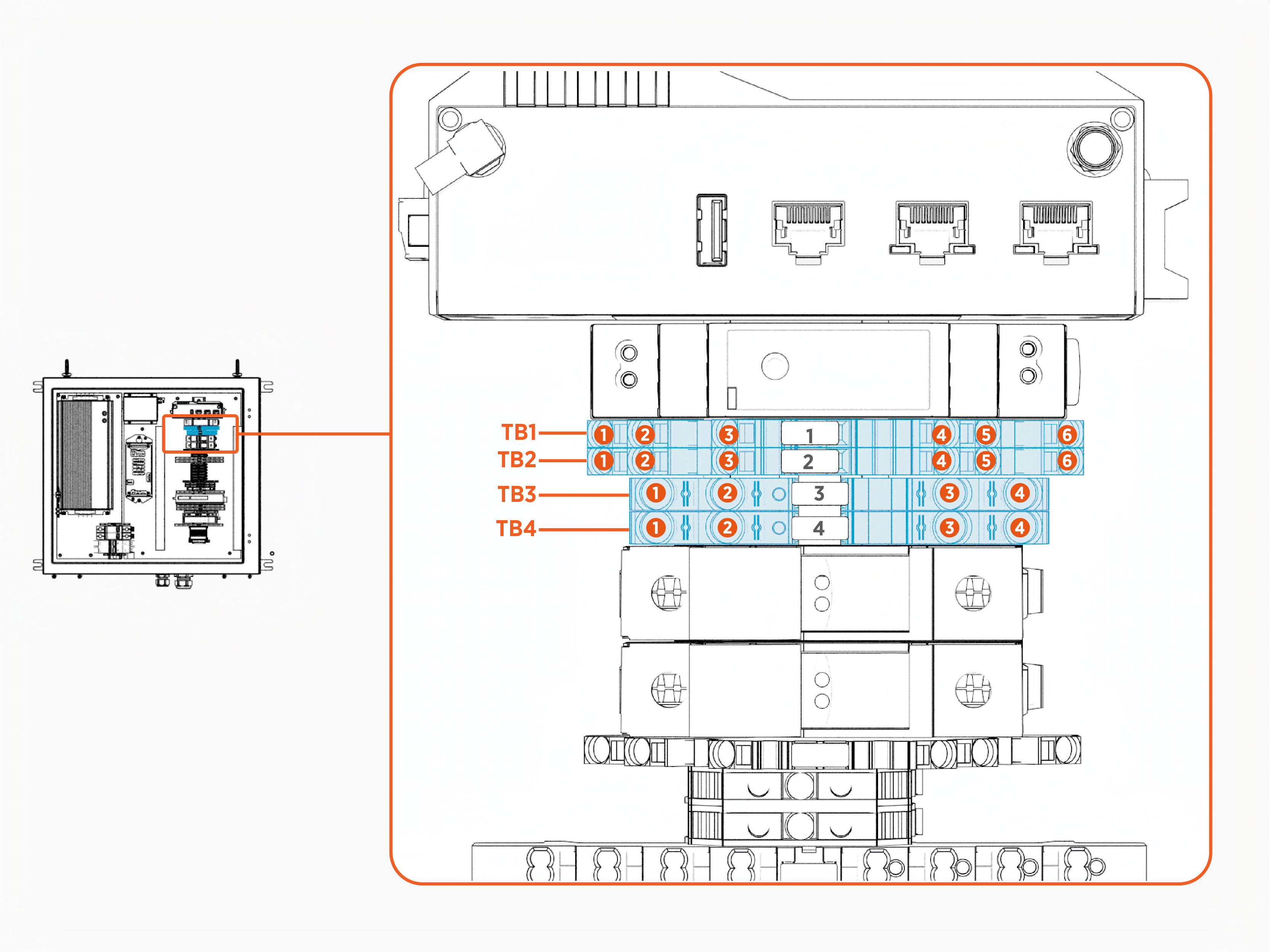
Terminal Block Components
.png)
|
Symbol |
Component Type |
Color |
Description |
|---|---|---|---|
|
TBA |
Terminal Block |
GREEN/YELLOW |
AC power Protective Earth (PE) distribution |
|
TBB |
Terminal Block |
GREEN/YELLOW |
Field landing for AC power Protective Earth (PE) |
|
Symbol |
Component Type |
Color |
Description |
|---|---|---|---|
|
TB1 |
Terminal Block |
GREEN/YELLOW |
System ground distribution |
|
TB2 |
Terminal Block |
GREEN/YELLOW |
System ground distribution and field landing from Power Link |
|
TB3 |
Terminal Block |
GRAY |
24 V power distribution |
|
TB4 |
Terminal Block |
GRAY |
24 V power distribution |
|
Symbol |
Component Type |
Color |
Description |
|---|---|---|---|
|
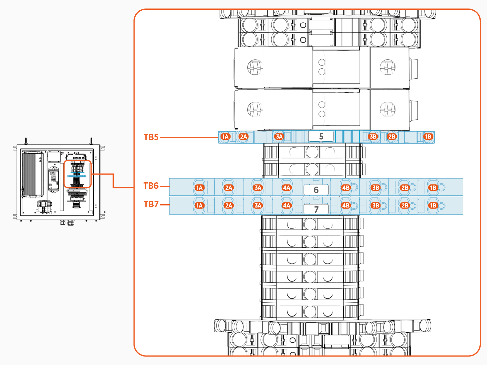
TB5 |
Terminal Block |
BLUE |
Field landing for Control Pilot (CP) |
|
TB6 |
Terminal Block |
BLUE |
Field landing for status LED |
|
TB7 |
Terminal Block |
BLUE |
Field landing for status LED |
|
Symbol |
Component Type |
Color |
Description |
|---|---|---|---|
|
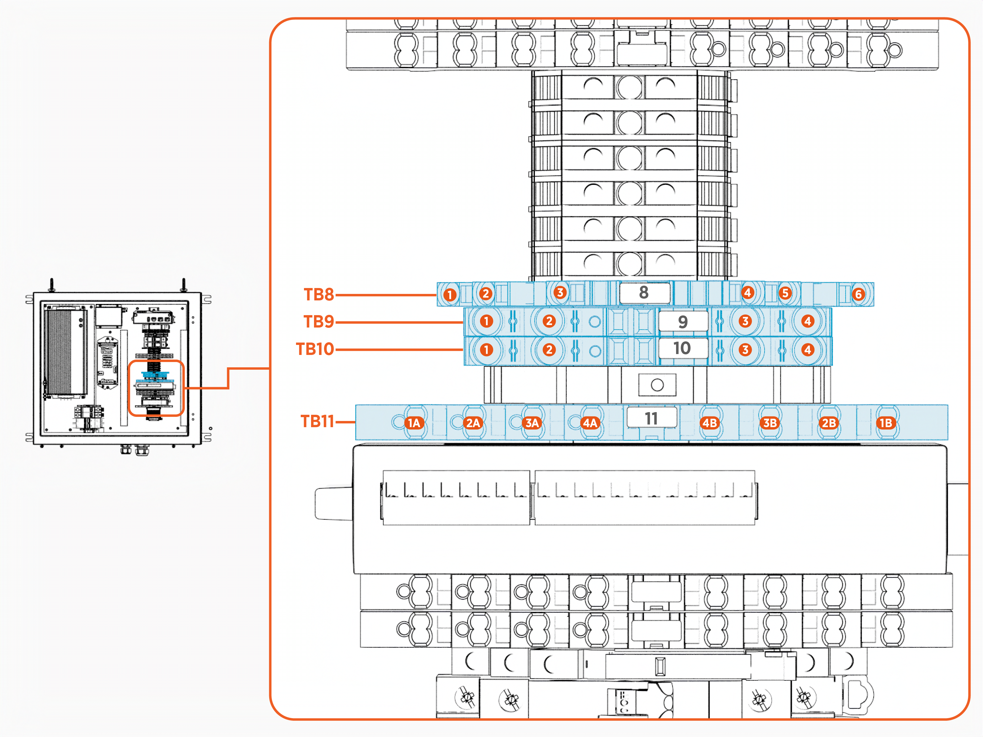
TB8 |
Terminal Block |
GREEN/YELLOW |
Field landing for system ground to pantograph |
|
TB9 |
Terminal Block |
BLUE |
Field landing for low current 24V to pantograph |
|
TB10 |
Terminal Block |
Field landing for high current 24V to pantograph |
|
|
TB11 |
Terminal Block |
WHITE |
Field landing for pantograph status signals |
|
Symbol |
Component Type |
Color |
Description |
|---|---|---|---|
|
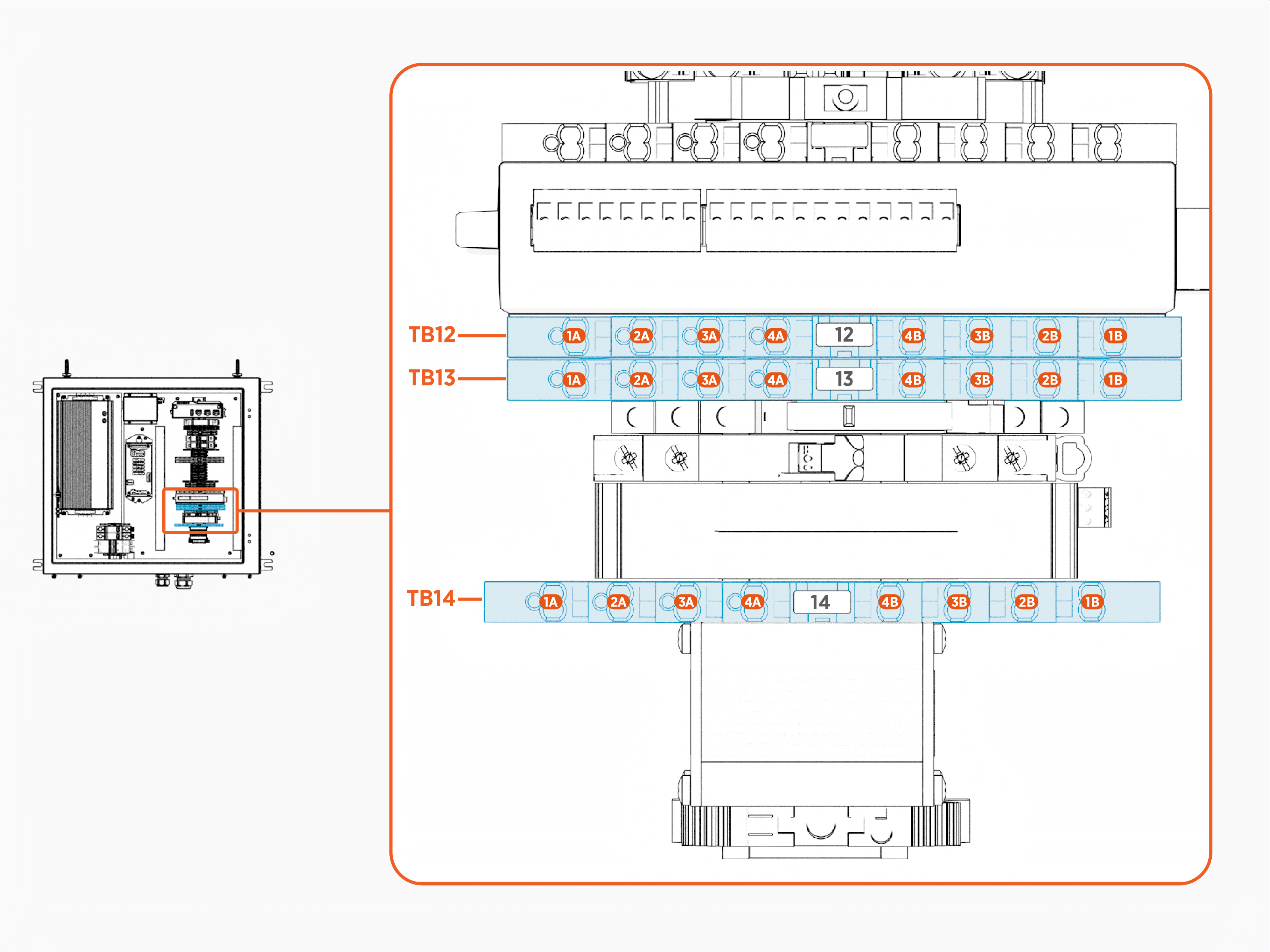
TB12 |
Terminal Block |
GRAY |
Field landing for pantograph control signals |
|
TB13 |
Terminal Block |
GRAY |
Field landing for pantograph control signals |
|
TB14 |
Terminal Block |
WHITE |
Field landing for 48 V from Power Link |
Control Switch Components

|
Symbol |
Component Type |
Color |
Description |
|---|---|---|---|
|
SW1 |
Switch |
GRAY |
Pantograph manual operation switch |
|
SW2 |
Switch |
BLACK |
24 V power supply enable relay |
|
SW3 |
Switch |
GRAY |
24 V power supply enable manual override |
Critical Modules

|
Symbol |
Component Type |
Color |
Description |
|---|---|---|---|
|
M1 |
Module |
GRAY |
EV |
|
M2 |
Module |
BLACK |
Wi-Fi |
|
M3 |
Module |
GRAY |
24 V digital signal interface from SEVB |
|
M4 |
Module |
SILVER |
SEVB |
|
M5 |
Module |
SILVER |
External status LED driver board |
Signal LEDs
.png)
|
Symbol |
Component Type |
Color |
Description |
|---|---|---|---|
|
LED1 |
LED |
BLUE |
Request Raise/Retract status light |
|
LED2 |
LED |
YELLOW |
Request Lower/Extend status light |
|
LED3 |
LED |
High current 24 V status light |
|
|
LED4 |
LED |
Low current 24 V status light |
|
|
LED5 |
LED |
BLUE |
Raised/Retracted status light |
|
LED6 |
LED |
YELLOW |
Lowered/Extended status light |
|
LED7 |
LED |
WHITE |
Reserved for future use |
|
LED8 |
LED |
GREEN |
Rest position sensor status light |
PD Controller Faults
This section lists the PD Controller faults.
The PD Controller is also referred to as Universal Smart Charging Interface (USCI) for the Pantograph Down 2000 system.
urn:fault:usci:ac-surge-replacement-needed
Fault Description
AC surge protector is damaged and needs to be replaced.
|
Category |
Fault Source |
Fault Type |
Criticality |
|
USCI Surge Protection |
USCI |
Hardware |
Minor |
Possible Causes
-
Electrical surge
-
Terminal plug is not fully seated
-
Poor/missing wiring
Troubleshooting
-
Check status window on AC surge suppressors (SG3, SG4). Replace the surge cartridge if the status window is RED
 Route Enforcement Data.
 -
Check that the GREEN, three screw-terminal plugs are fully seated in the AC surge suppressor assemblies (SG3, SG4). Push so that it sits flush with the module.
-
Push-pull check that two wires are clamped in the outside terminals marked Nc and C on both AC surge suppressors (SG3, SG4).
-
If fault still exists, re-seat the surge cartridges, ensuring cartridges are fully inserted with no gap or misalignment.
urn:fault:usci:door-open
Fault Description
USCI door is open.
|
Category |
Fault Source |
Fault Type |
Criticality |
|
USCI Door |
USCI |
Hardware |
Critical |
Possible Causes
-
USCI door open
-
Magnet and sensor misaligned
-
Door sensor defective/damaged
Troubleshooting
-
Confirm USCI door is closed and locked.
-
Confirm that when door closes, the magnet on the door is close in height (but not overlapping) to the corresponding sensor on the enclosure.
-
Check that the magnet has the potted end facing downwards.
-
Check for wiring continuity from the door sensor to SEVB
Smart Ethernet Vehicle Board (M4) J5 (24-pin connector).
urn:fault:usci:48v-surge-replacement-needed
Fault Description
48V surge protector in the USCI is damaged and needs to be replaced.
|
Category |
Fault Source |
Fault Type |
Criticality |
|
USCI Surge Protection |
USCI |
Hardware |
Minor |
Possible Causes
-
Electrical surge
-
Terminal plug is not fully seated
-
Poor/missing wiring
Troubleshooting
-
Check that the GREEN, three screw-terminal plug is fully seated in the 48 V surge suppressor assembly (SG1). Push so that it sits flush with the module.
-
Push-pull check that two wires are clamped in the bottom two screw terminals on the 48 V surge suppressor.
-
Check resistance between bottom two screw terminals with it firmly inserted into the surge suppressor assembly. If high resistance, replace the 48 V surge cartridge.
urn:fault:usci:io-module-unreachable
Fault Description
IO module cannot be reached via the SEVB![]() Smart Ethernet Vehicle Board interface.
Smart Ethernet Vehicle Board interface.
|
Category |
Fault Source |
Fault Type |
Criticality |
|
USCI Pantograph Interface |
USCI |
Hardware/Software |
Critical |
Possible Causes
-
IO module (M3) defective/damaged
-
Ethernet cable defective/damaged
-
Access Point (M2) defective/damaged
-
Software issue
-
Poor/missing electrical connection
Troubleshooting
-
If urn:fault:usci:wireless-ap-unreachable is present, resolve that fault first and check if io-module-unreachable fault is still present.
-
If fault occurred after SW update, revert SW.
-
Check that the Ethernet cable is securely connected from wireless AP (M2) LAN2 to IO module (M3) port 2.
-
If none of the status lights on the IO module (M3) are on when the USCI is powered, check that there is 24 V across V+ to V- and V+ to PE on M3. Wires may have gotten disconnected and need to be reterminated.
-
Replace the IO module (M3).
-
Replace the wireless AP (M2).
-
Replace the Ethernet cable between wireless AP (M2) and IO module (M3)
urn:fault:usci:wireless-ap-unreachable
Fault Description
AP cannot be reached via the SEVB![]() Smart Ethernet Vehicle Board interface.
Smart Ethernet Vehicle Board interface.
|
Category |
Fault Source |
Fault Type |
Criticality |
|
USCI Wi-Fi |
USCI |
Hardware/Software |
Critical |
Possible Causes
-
Ethernet cable defective/damaged
-
Access Point (M2) defective/damaged
-
Software issue
-
Poor/missing electrical connection
Troubleshooting
-
If fault occurred after SW update, revert SW.
-
If none of the status lights on the AP module (M2) are on when the USCI is powered, check that there is 24 V across PWR1+ to PWR1-. Wires may have gotten disconnected and need to be reterminated.
-
Check the Ethernet cable is securely connected from SEVB
Smart Ethernet Vehicle Board J9 (6-pin connector on M4) to LAN1 on the AP (M2). -
Replace the Ethernet cable from SEVB
Smart Ethernet Vehicle Board J9 (6-pin connector on M4) to LAN1 on the AP (M2). -
Replace the AP module (M2).
urn:fault:usci:rfid-reader-unreachable
Fault Description
RFID![]() Radio Frequency IDentification reader cannot be reached via the SEVB
Radio Frequency IDentification reader cannot be reached via the SEVB![]() Smart Ethernet Vehicle Board interface.
Smart Ethernet Vehicle Board interface.
|
Category |
Fault Source |
Fault Type |
Criticality |
|
USCI RFID |
USCI |
Hardware/Software |
Major |
Possible Causes
-
RFID
Radio Frequency IDentification module (M1) defective/damaged -
IO module (M3) defective/damaged
-
Ethernet cable defective/damaged
-
Access Point (M2) defective/damaged
-
5 V Power Supply PS2 defective/damaged
-
Software issue
-
Poor/missing electrical connection
Troubleshooting
-
If wireless-ap-unreachable fault is present, resolve that fault first.
-
If io-module-unreachable fault is present, resolve that fault first.
-
If there are no visible lights on the RFID
Radio Frequency IDentification module (M1) -- LEDs are located near the power connector -- check for 5V across +Vo and -Vo on PS2 and check that the barrel plug is fully seated in the +5 VDC port of the RFID Radio Frequency IDentification module. If 5 V is not present across +Vo and -Vo on PS2, check that the wires are terminated securely on both the input and output side of the power supply. If measuring 24V across +VIn and -VIn on PS2 and not measuring 5 V across +Vo and -Vo, disconnect the power plug from the RFID Radio Frequency IDentification module M1. If +Vo to -Vo is still not measuring 5 V, replace PS2. -
Check for secure Ethernet connection from RFID
Radio Frequency IDentification module (M1) LAN Local Area Network to IO module (M3) Port 1. -
Replace the RFID
Radio Frequency IDentification module (M1). -
Replace the IO module (M3).
-
Replace the Ethernet cable from RFID
Radio Frequency IDentification module (M1) LAN Local Area Network to IO module (M3) Port 1.
urn:fault:usci:pantograph-retract-timeout
Fault Description
Retracted signal not observed within 19 seconds of commanding the panto to retract.
|
Category |
Fault Source |
Fault Type |
Criticality |
|
Pantograph |
Pantograph or USCI |
Hardware |
Minor |
Possible Causes
-
Pantograph defective/damaged
-
IO module (M3) defective/damaged
-
Poor electrical connection - pantograph supply voltage may be too low
Troubleshooting
-
If pantograph-retract-timeout-critical is present, resolve that fault first.
-
Visually inspect pantograph for anything impeding retraction. Remove any impediments.
-
Service pantograph to ensure it is performing nominally.
-
Check the quality of the connections at TB10 and at all of the TB8 connections. Check connection quality at both ends of fuse holder F2. Check connection quality at the primary power supply (PS1) +V and -V.
urn:fault:usci:pantograph-extend-timeout
Fault Description
Extended signal not observed within 19 seconds of commanding the panto to extend.
|
Category |
Fault Source |
Fault Type |
Criticality |
|
Pantograph |
Pantograph or USCI |
Hardware |
Minor |
Possible Causes
-
Pantograph defective/damaged
-
IO module (M3) defective/damaged
-
Poor electrical connection - pantograph supply voltage may be too low
Troubleshooting
-
If pantograph-extend-timeout-critical is present, resolve that fault first.
-
Visually inspect pantograph for anything impeding extension. Remove any impediments.
-
Service pantograph to ensure it is performing nominally.
-
Check the quality of the connections at TB10 and at all of the TB8 connections. Check connection quality at both ends of fuse holder F2. Check connection quality at the primary power supply (PS1) +V and -V.
urn:fault:usci:pantograph-retract-timeout-critical
Fault Description
Retracted signal not observed within 20 seconds of commanding the panto to retract. (20 seconds required by V2G_SECC![]() Supply Equipment Communication Controller_ACD_Disconnection_Timeout in V2G2-OC-724 of SAE J3105:2023).
Supply Equipment Communication Controller_ACD_Disconnection_Timeout in V2G2-OC-724 of SAE J3105:2023).
|
Category |
Fault Source |
Fault Type |
Criticality |
|
Pantograph |
Pantograph or USCI |
Hardware |
Critical |
Possible Causes
-
Pantograph defective/damaged - pantograph may not be receiving request retract signal or signaling retracted correctly.
-
IO module (M3) defective/damaged - request retract signal may not be driven correctly or the retracted signal may not be detected correctly.
-
Poor/missing electrical connection - connection path from pantograph to the IO module (M3) can be broken on request retract signal or retracted signal.
Troubleshooting
-
If Pantograph isn't retracting/raising at all and is stuck in the extended position, reboot the Power Link to disable power on the USCI, which removes power to the Pantograph. If the Pantograph does not retract at this time, the Pantograph must be serviced. When the Pantograph loses power, it will retract without any signaling from the USCI.
-
If the Pantograph isn't retracting/raising as expected but then retracts when the PL is rebooted in step 1, then the "request retract" signal may not be properly received by the Pantograph. Check that BLUE LED1 is lit when trying to retract the Pantograph (i.e. via manual operation). If it isn't, check the voltage across LED1. If 24V, replace the LED. If less than 5V, check that the BLUE/WHITE striped wire from the interface cable is terminated securely at TB13 4B and that TB13 4A is securely connected to IO module (M3) DO 0. If TB13 4B is ~0 ohms to IO module (M3) DO 0 and the voltage is less than 5V across LED1, replace the IO module (M3). If the voltage is instead 24V, then the interface cable needs to be checked for continuity from the striped BLUE/WHITE bare wire to pin 8 on the Harting connector at the Schunk pantograph. If full connection path looks good, then service the Pantograph electrical system.
-
If this fault is raised and the Pantograph appears to be retracting normally, check that the BLUE LED5 is lit when the Pantograph is fully raised. If it isn't, check the voltage across LED5. If 24V, replace the LED. If 24V is measred at M3 DI 2 and panto operation is as expected, replace the IO module (M3). If less than 5V, check that the solid BLUE wire from the interface cable is terminated securely at TB11 4B and that TB11 4A is securely connected to IO module (M3) DI 2. If TB11 4B is ~0 ohms to IO module (M3) DI 2, then the interface cable needs to be checked for continuity from the solid BLUE bare wire to pin 6 on the Harting connector at the Schunk pantograph. Otherwise, if seeing less than 5V at M3 and full connection path looks good, then service the Pantograph.
urn:fault:usci:pantograph-extend-timeout-critical
Fault Description
Extended signal not observed within 20 seconds of commanding the panto to extend and retract the Pantograph. (20 seconds required by V2G_SECC![]() Supply Equipment Communication Controller_ACD_Connection_Timeout in V2G2-OC-704 of SAE J3105:2023)
Supply Equipment Communication Controller_ACD_Connection_Timeout in V2G2-OC-704 of SAE J3105:2023)
|
Category |
Fault Source |
Fault Type |
Criticality |
|
Pantograph |
Pantograph or USCI |
Hardware |
Critical |
Possible Causes
-
Pantograph defective/damaged - Pantograph may not be receiving request extend signal or signaling extended correctly.
-
IO module (M3) defective/damaged - request extend signal may not be driven correctly or the extended signal may not be detected correctly.
-
Poor/missing electrical connection - connection path from Pantograph to the IO module (M3) can be broken on request extend signal or extended signal.
Troubleshooting
-
If the Pantograph isn't extending/lowering as expected then the request extend signal may not be properly received by the Pantograph. Check that YELLOW/amber LED2 is lit when trying to extend the Pantograph (i.e. via manual operation). If it isn't, check the voltage across LED2. If 24 V, replace the LED. If less than 5 V, check that the YELLOW/WHITE striped wire from the interface cable is terminated securely at TB13 3B and that TB13 3A is securely connected to IO module (M3) DO 1. If TB13 3B is ~0 ohms to IO module (M3) DO 1 and the voltage is less than 5V across LED2, replace the IO module (M3). If the voltage is instead 24 V, then the interface cable needs to be checked for continuity from the striped YELLOW/WHITE bare wire to pin 9 on the Harting connector at the Schunk pantograph. If full connection path looks good, then service the Pantograph electrical system.
-
If this fault is raised and the Pantograph appears to be extending normally, check that the YELLOW LED6 is lit when the Pantograph is fully lowered. If it isn't, check the voltage across LED6. If 24 V, replace the LED. If 24 V is measured at M3 DI 3 and panto operation is as expected, replace the IO module (M3). If less than 5 V, check that the solid YELLOW wire from the interface cable is terminated securely at TB11 3B and that TB11 3A is securely connected to IO module (M3) DI 3. If TB11 3B is ~0 ohms to IO module (M3) DI 3, then the interface cable needs to be checked for continuity from the solid YELLOW bare wire to pin 7 on the Harting connector at the Schunk pantograph. Otherwise, if seeing less than 5 V at M3 and full connection path looks good, then service the Pantograph.
urn:fault:usci:pantograph-rest-sensor-error
Fault Description
Rest sensor not active when Pantograph is signaling retracted.
|
Category |
Fault Source |
Fault Type |
Criticality |
|
Pantograph |
Pantograph or USCI |
Hardware |
Critical |
Possible Causes
-
Pantograph retraction physically impeded
-
IO module (M3) defective/damaged - rest sensor signal may not be detected correctly
-
Missing/broken electrical connection from Pantograph rest sensor to IO module (M3)
-
Rest sensor on pantograph defective/damaged
Troubleshooting
-
If Pantograph is not fully retracting to the home/rest position, remove any obstacle or impediment.
-
If Pantograph is not fully retracting to the home/rest position and there are no restrictions, service the pantograph.
-
If this fault is raised and the Pantograph appears to be fully retracted to the home/rest position, check that the GREEN LED8 is lit when the pantograph is fully raised. If it isn't, check the voltage across LED8. If 24 V, replace the LED. If 24 V is measured at M3 DI 5, replace the IO module (M3). If less than 5 V, check that the GREEN/BLUE striped wire from the interface cable is terminated securely at TB11 1B and that TB11 1A is securely connected to IO module (M3) DI 5. If TB11 1 is ~0 ohms to IO module (M3) DI 5, then the interface cable needs to be checked for continuity from the GREEN/BLUE striped bare wire to pin 4 on the 4-pin M12 connector at the Schunk pantograph. Next, check that 24 V is present on TB9 3. If not, check the fuse at F1 and the connection from TB9 to F1. If yes, check that 24 V is present along the interface cable to the rest sensor relative to the ground fed to the rest sensor. If seeing less than 5 V at M3 and full connection path for 24 V, ground, and signal to the sensor looks good, then service the Pantograph.
urn:fault:usci:pantograph-extended-lost
Fault Description
Pantograph was extended and then lost the extended signal without any retraction command.
|
Category |
Fault Source |
Fault Type |
Criticality |
|
Pantograph |
Pantograph or USCI |
Hardware |
Critical |
Possible Causes
-
Pantograph defective/damaged - Extended signal not driven correctly
-
Missing/broken electrical connection from Pantograph to IO module (M3) - Extended signal
-
IO module (M3) defective/damaged - Extended signal not read correctly
Troubleshooting
Manually extend the Pantograph; at full extension, check that the YELLOW/amber LED6 is on. If it isn't, check the voltage across LED6. If 24V, replace the LED. If 24V is measured at M3 DI 3 and an extension fault is present, replace the IO module (M3). If less than 5V is measured at M3 DI 3, check continuity from M3 DI 3 to TB11 3B, tracing the solid YELLOW wires. If continuity looks good, then check resistance from the field-landed solid YELLOW bare wire to pin 7 on the Harting connector at the pantograph. If that looks good, then service the Pantograph.
urn:fault:usci:pantograph-retracted-lost
Fault Description
Pantograph was retracted and then lost the retracted signal without any extension command.
|
Category |
Fault Source |
Fault Type |
Criticality |
|
Pantograph |
Pantograph or USCI |
Hardware |
Major |
Possible Causes
-
Pantograph defective/damaged - Retracted signal not driven correctly
-
Missing/broken electrical connection from pantograph to IO module (M3) - Retracted signal
-
IO module (M3) defective/damaged - Retracted signal not read correctly
Troubleshooting
Manually retract the Pantograph; at full retraction, check that the BLUE LED5 is on. If it isn't, check the voltage across LED5. If 24V, replace the LED. If 24V is measured at M3 DI 2 and a retraction fault is present, replace the IO module (M3). If less than 5V is measured at M3 DI 2, check continuity from M3 DI 2 to TB11 4B, tracing the solid BLUE wires. If continuity looks good, then check resistance from the field-landed solid BLUE bare wire to pin 6 on the Harting connector at the pantograph. If that looks good, then service the Pantograph.
urn:fault:usci:pantograph-unknown-position
Fault Description
No active Extended signal and no rest sensor signal a significant amount of time after commanding in a certain direction. Pantograph shall always be either in the home/rest position or the fully extended position in steady state. If pantograph is not in either of these states 30 seconds after the last pantograph movement command is sent and the pantograph position is unknown.
|
Category |
Fault Source |
Fault Type |
Criticality |
|
Pantograph |
Pantograph or USCI |
Hardware |
Critical |
Possible Causes
-
Fuse(s) blown
-
Other Pantograph fault present
Troubleshooting
-
Address any other faults first.
-
Check fuses F1 and F2 and replace as necessary.
-
Check for 24 V from TB9 4 and TB9 3 to TB8 4. Check for 24 V from TB10 4 to TB8 5. If 24 V not present, check wiring.
-
Check for 24 V at the Pantograph Harting connector from Pin 1 to Pin 2 and from Pin 3 to Pin 4. If not present but present at the USCI, replace the interface cable or resolve connection issues. If both 24 V are validated at the connector and this fault is still present, service the Pantograph.
urn:fault:usci:pantograph-stuck-at-rest-position
Fault Description
Rest position active but Retracted signal is not present.
|
Category |
Fault Source |
Fault Type |
Criticality |
|
Pantograph |
Pantograph or USCI |
Hardware |
Critical |
Possible Causes
-
Pantograph extension is physically impeded
-
Pantograph signalling defective/damaged - Retracted signal not driven correctly
-
IO module (M3) defective/damaged - Retracted signal not read correctly
-
Missing/broken electrical connection from pantograph to IO module (M3) - Retracted signal
Troubleshooting
-
Remove any objects that impede the pantograph's ability to lower.
-
If fault is present when pantograph is not in the fully raised position, check if GREEN LED8 is brightly lit with the pantograph lowered. If yes, the voltage across it will measure 24V. Disconnect the striped GREEN/BLUE wire from TB11 1B. If the LED turns off/dim, the pantograph rest sensor needs to be serviced. If LED8 remains brightly lit with the GREEN/BLUE striped wire on TB11 1B disconnected, validate the voltage is 24V, check for any miswiring that would short the signal to 24V. Then, replace the IO module (M3).
-
If LED8 is dim/off with the pantograph lowered and the fault present, measure the voltage across LED8. If 24V, replace the LED and check step 2. If less than 5V, replace the IO module (M3).
-
If fault is raised with pantograph in the fully raised position, check if BLUE LED5 is brightly lit. If yes, the voltage across it will measure 24V. Validate that this 24V is seen at IO module (M3) DI 2. If yes, replace the IO module (M3).
-
If fault is raised with pantograph in the fully raised position and BLUE LED5 is not brightly lit, then check the voltage across LED5. If 24V, replace the LED and go to previous step. If less than 5V, check continuity from IO module (M3) DI 2 to TB11 4B (solid BLUE wire). If that looks good, then check continuity from the field-landed solid BLUE wire to pin 6 on the Harting connector at the pantograph. If that looks good, then service the pantograph.
urn:fault:usci:pantograph-position-signal-error
Fault Description
Both extended and retracted signals are active at the same time.
|
Category |
Fault Source |
Fault Type |
Criticality |
|
Pantograph |
Pantograph or USCI |
Hardware |
Major |
Possible Causes
-
Pantograph signalling defective/damaged - Retracted signal and/or Extended signal stuck at 24 V.
-
IO module (M3) defective/damaged - Retracted signal and/or Extended signal being falsely read as logic high
-
Miswiring - Retracted signal and/or Extended signal is shorted to 24 V
Troubleshooting
-
If fault is present and IO module (M3) DI 2 or DI 3 are not at 24 V, replace M3.
-
If fault is present and IO module (M3) DI 2 and DI 3 are at 24 V, disconnect the solid BLUE wire at TB11 4B and the solid YELLOW wire at TB11 3B. Check DI 2 and DI 3 again, if either are still at 24 V, check for any miswiring along the path that may short to 24 V. Otherwise, replace M3.
-
With the solid BLUE and solid YELLOW wires coming from the pantograph disconnected from TB11, measure the voltage on both. If both of them are 24 V, service the pantograph.
urn:fault:usci:ev-abnormal-closed-comms
Fault Description
TCP session closed by the EV![]() Electric Vehicle outside of a normal shutdown sequence (i.e. CP still state C).
Electric Vehicle outside of a normal shutdown sequence (i.e. CP still state C).
|
Category |
Fault Source |
Fault Type |
Criticality |
|
Charging Communications |
EV |
Software/Hardware |
Critical |
Possible Causes
-
EV
Electric Vehicle communications closed without a normal shutdown sequence as per SAE J3105 -
Other communication fault present
Troubleshooting
-
Resolve other faults.
-
Contact EV
Electric Vehicle OEM Original Equipment Manufacturer and ChargePoint for support.
urn:fault:usci:wireless-ev-communication-lost
Fault Description
Message sequence timeout reached in charging communication.
|
Category |
Fault Source |
Fault Type |
Criticality |
|
Charging Communications |
EV |
Software/Hardware |
Critical |
Possible Causes
-
Wi-Fi
Wireless Fidelity communications between EV Electric Vehicle and EVSE Electric Vehicle Supply Equipment have been lost/interrupted
-
EV
Electric Vehicle hasn't sent a message within the SAE J3105 timeout
Troubleshooting
-
Attempt another charge session; if charging does not start, check for the station Wi-Fi
Wireless Fidelity networks underneath the station with any Wi-Fi Wireless Fidelity device (phone/laptop). If the Wi-Fi Wireless Fidelity networks containing the station name are not present with good signal strength, check and replace the AP (M2) or the Wi-Fi Wireless Fidelity antenna assembly (including surge suppressor). If the Wi-Fi Wireless Fidelity networks are present with good signal strength and charging is not starting, try with another EV Electric Vehicle and contact EV Electric Vehicle OEM Original Equipment Manufacturer and ChargePoint for support. -
If issue is intermittent, check if the issue follows a specific EV
Electric Vehicle and service that EV Electric Vehicle. -
If issue is intermittent and the issue follows a specific station, check that all coaxial connections from M2 to the Wi-Fi
Wireless Fidelity antenna are properly secured and torqued. If no bad connections, then look at replacing M2 and/or the Wi-Fi Wireless Fidelity antenna assembly. Lastly, replace the Ethernet cable from M2 LAN1 to the SEVB Smart Ethernet Vehicle Board (M4) J9 (6-pin connector).
urn:fault:usci:pantograph-ev-alignment-error
Fault Description
Pantograph fully extended but CP still in state A, indicating the pantograph has not successfully made contact with the EV![]() Electric Vehicle.
Electric Vehicle.
|
Category |
Fault Source |
Fault Type |
Criticality |
|
EV |
EV |
Hardware |
Critical |
Possible Causes
-
EV
Electric Vehicle misalignment; pantograph rails not making contact with bus rails or EV Electric Vehicle is not in the correct orientation -
Missing/broken electrical connection from pantograph to PL (PE) or USCI (Control Pilot)
-
Defective/damaged SEVB
Smart Ethernet Vehicle Board -
EV
Electric Vehicle CP/PE circuit issue
Troubleshooting
-
Resolve any other pantograph faults first if present.
-
Visually verify bus alignment and that the 4 pantograph rails are making contact with the 4 bus rails.
-
Verify the bus driving direction matches the pantograph orientation.
-
With no EV
Electric Vehicle present, measure the voltage from the pantograph CP rail to the PE rail. If not ~12 V, check signal continuity back to the SEVB Smart Ethernet Vehicle Board (M4 J5 pins 2 and 24). If continuity looks good and ~12 V not present when SEVB Smart Ethernet Vehicle Board is powered, replace the SEVB Smart Ethernet Vehicle Board assembly (M4+M5). -
If issue only occurs with one EV
Electric Vehicle or EV Electric Vehicle model and does not occur on others, contact the vehicle OEM Original Equipment Manufacturer for support.
urn:fault:usci:pantograph-ev-state-c-timeout
Fault Description
EV![]() Electric Vehicle fails to transition from State B to State C within the timeout defined by OppCharge/SAE J3105.
Electric Vehicle fails to transition from State B to State C within the timeout defined by OppCharge/SAE J3105.
|
Category |
Fault Source |
Fault Type |
Criticality |
|
EV |
EV |
Hardware |
Critical |
Possible Causes
EV![]() Electric Vehicle hasn't signalled charge readiness according to SAE J3105.
Electric Vehicle hasn't signalled charge readiness according to SAE J3105.
Troubleshooting
Contact EV![]() Electric Vehicle OEM
Electric Vehicle OEM![]() Original Equipment Manufacturer to service the EV
Original Equipment Manufacturer to service the EV![]() Electric Vehicle.
Electric Vehicle.
urn:fault:usci:pantograph-isolation-monitoring-timeout
Fault Description
Isolation monitoring check exceeds timeout.
|
Category |
Fault Source |
Fault Type |
Criticality |
|
Isolation Monitoring |
USCI |
Hardware/Software |
Critical |
Possible Causes
-
DC+ to DC- voltage not stable
-
IMD not operating as expected
Troubleshooting
-
Check and resolve Power Module faults on the Power Block
-
If issues still present after eliminating PM faults, replace the Proton
urn:fault:usci:comms-performance-time-violation
Fault Description
Warning is triggered when a V2G response message is not sent within the required performance time after receiving the corresponding request.
|
Category |
Fault Source |
Fault Type |
Criticality |
|
Charging Communications |
USCI |
Software |
Minor |
Possible Causes
Software/firmware timing performance.
Troubleshooting
Contact ChargePoint for support.
urn:fault:usci:rfid-ppd-tag-not-found
Fault Description
Occurs when the EV![]() Electric Vehicle RFID
Electric Vehicle RFID![]() Radio Frequency IDentification tag is not read, despite V2G communication indicating that an RFID
Radio Frequency IDentification tag is not read, despite V2G communication indicating that an RFID![]() Radio Frequency IDentification is present.
Radio Frequency IDentification is present.
|
Category |
Fault Source |
Fault Type |
Criticality |
|
RFID |
EV |
Hardware |
Critical |
Possible Causes
-
EV
Electric Vehicle RFID Radio Frequency IDentification tag not present -
EV
Electric Vehicle RFID Radio Frequency IDentification tag is shielded by physical obstruction -
EV
Electric Vehicle RFID Radio Frequency IDentification tag is not type specified in SAE J3105-1:2023 -
EV
Electric Vehicle RFID Radio Frequency IDentification tag not placed in the location specified by SAE J3105-1:2023 -
EV
Electric Vehicle RFID Radio Frequency IDentification tag not sensitive enough to be read at the application range -
RFID
Radio Frequency IDentification antenna damaged/defective -
RFID
Radio Frequency IDentification coaxial connection damaged/defective -
RFID
Radio Frequency IDentification module (M1) damaged/defective -
RFID
Radio Frequency IDentification module is connected to an incorrect RFID Radio Frequency IDentification antenna
Troubleshooting
-
Check if the EV
Electric Vehicle is able to charge on a different station. If able to charge on a different station, check that all coaxial connection are properly secured and torqued from the RFID Radio Frequency IDentification module (M1) to the correct RFID Radio Frequency IDentification antenna. If all connections are secure and fault still occurs, replace the RFID Radio Frequency IDentification module (M1) and/or the RFID Radio Frequency IDentification antenna assembly. -
If the EV
Electric Vehicle is not able to charge on a different station, use a test RFID Radio Frequency IDentification tag under the pantograph to validate that the system is able to read the tag successfully. If no, check that all coaxial connection are properly secured and torqued from the RFID Radio Frequency IDentification module (M1) to the RFID Radio Frequency IDentification antenna. If all connections are secure and test RFID Radio Frequency IDentification is still not read, replace the RFID Radio Frequency IDentification module (M1) and/or the RFID Radio Frequency IDentification antenna assembly. -
If the EV
Electric Vehicle is not able to charge and the test RFID Radio Frequency IDentification tag is read successfully, ensure there is nothing obstructing the EV Electric Vehicle RFID Radio Frequency IDentification tag and then service the EV Electric Vehicle to ensure the tag is programmed, placed, and designed correctly as per SAE J3105.
urn:fault:usci:rfid-ppd-incorrect-tag-found
Fault Description
When EV![]() Electric Vehicle RFID
Electric Vehicle RFID![]() Radio Frequency IDentification tag is read but RFID
Radio Frequency IDentification tag is read but RFID![]() Radio Frequency IDentification tag doesn't match the communicated EVCCID.
Radio Frequency IDentification tag doesn't match the communicated EVCCID.
|
Category |
Fault Source |
Fault Type |
Criticality |
|
RFID |
EV |
Hardware |
Critical |
Possible Causes
-
EV
Electric Vehicle RFID Radio Frequency IDentification tag not programmed to match communicated EVCC Electric Vehicle Communication Controller ID -
EV
Electric Vehicle RFID Radio Frequency IDentification tag not present -
EV
Electric Vehicle RFID Radio Frequency IDentification tag is shielded by physical obstruction -
EV
Electric Vehicle RFID Radio Frequency IDentification tag is not the type specified in SAE J3105-1:2023 -
EV
Electric Vehicle RFID Radio Frequency IDentification tag not placed in the location specified by SAE J3105-1:2023 -
EV
Electric Vehicle RFID Radio Frequency IDentification tag not sensitive enough to be read at the application range -
RFID
Radio Frequency IDentification antenna damaged/defective -
RFID
Radio Frequency IDentification module is connected to an incorrect RFID Radio Frequency IDentification antenna
Troubleshooting
-
Check if the EV
Electric Vehicle is able to charge on a different station. If able to charge on a different station, check that all coaxial connection are properly secured and torqued from the RFID Radio Frequency IDentification module (M1) to the correct RFID Radio Frequency IDentification antenna. If all connections are secure and fault still occurs, replace the RFID Radio Frequency IDentification module (M1) and/or the RFID Radio Frequency IDentification antenna assembly. -
If the EV
Electric Vehicle is not able to charge on a different station, use a test RFID Radio Frequency IDentification tag under the pantograph to validate that the system is able to read the tag successfully. If no, check that all coaxial connection are properly secured and torqued from the RFID Radio Frequency IDentification module (M1) to the RFID Radio Frequency IDentification antenna. If all connections are secure and test RFID Radio Frequency IDentification is still not read, replace the RFID Radio Frequency IDentification module (M1) and/or the RFID Radio Frequency IDentification antenna assembly. -
If the EV
Electric Vehicle is not able to charge and the test RFID Radio Frequency IDentification tag is read successfully, ensure there is nothing obstructing the EV Electric Vehicle RFID Radio Frequency IDentification tag and then service the EV Electric Vehicle to ensure the tag is programmed, placed, and designed correctly as per SAE J3105.
urn:fault:usci:sevb-usc-unreachable
Fault Description
SEVB![]() Smart Ethernet Vehicle Board-USC within the USCI is unreachable.
Smart Ethernet Vehicle Board-USC within the USCI is unreachable.
|
Category |
Fault Source |
Fault Type |
Criticality |
|
SEVB |
Hardware |
Critical |
Possible Causes
-
24V Power Supply not receiving AC power
-
Enable signal not present at the Power Supply
-
Ethernet surge suppressor damaged
-
Wiring installation issue or disconnected
Troubleshooting
-
Check that single-phase AC power (120-277 VAC) is energized to the USCI.
-
Is the USCI visibly powered? (lights on?) If yes, skip to step 5. If no, continue with the following.
-
Check that the breaker CB1 is in the ON position. If AC power is reaching the power supply input, the status LED at the top of PS1 will be RED
Route Enforcement Data or GREEN. If not on, check connections and validate AC voltage. If correct AC voltage is validated at the power supply (PS1) input and the status LED on PS1 is not lit, replace PS1. -
If status light is RED
Route Enforcement Data and Power Link is powered on, measure the voltage across TB14 1A and TB14 2A. If this is not 48 V, check the terminal block connections in the Power Link to ensure the wires are landed securely. If 48 V, check that 48 V is present across A1+ and A2- on relay SW2. If no, fix wiring. If yes, check resistance from 11 to 14 on SW2. If resistance is ~0 ohms, check the gray wiring from SW2 to SW3 to PS1 CN71. If high resistance across 11 and 14 and 48 V is present across A1+ and A2-, replace the SW2 relay. -
If the USCI is visibly powered, check for blinking GREEN LEDs on the SEVB
Smart Ethernet Vehicle Board (M4). If none, check wiring from M4 J6 (4-pin connector) back to TB1 2 and TB4 2 to ensure there is 24V present. If connector looks good and 24 V is confirmed present, replace the SEVB Smart Ethernet Vehicle Board module (M4+M5). -
Otherwise, if SEVB
Smart Ethernet Vehicle Board appears powered, check the Ethernet connection path from SEVB Smart Ethernet Vehicle Board to SSLAN Smart Switch Local Area Network. Check that the top-most SSLAN Smart Switch Local Area Network Ethernet ports are used. There is one blank port on the SSLAN Smart Switch Local Area Network towards the bottom that cannot be used. Once all connections are verified from SSLAN Smart Switch Local Area Network to Ethernet surge suppressor in the PL, to Ethernet surge suppressor in the USCI (SG2), to SEVB Smart Ethernet Vehicle Board (M4), test the field landed Ethernet cable and reterminate/replace as needed. Otherwise, replace the cable from USCI surge suppressor (SG2) to SEVB Smart Ethernet Vehicle Board (M4) first. Then, try bypassing or using new Ethernet surge suppressors to check if either needs to be replaced. Then, check the remaining cable and replace as needed. If issues persist and no other faults present, replace the SSLAN Smart Switch Local Area Network.
urn:fault:fdc:acd-thermal-switch-open
Fault Description
The side DC landing on the Power Link 2000 has reached abnormally high temperature.
|
Category |
Fault Source |
Fault Type |
Criticality |
|
Thermal Switch |
Thermal Switch |
Hardware |
Critical |
Possible Causes
-
Sensor connection issue
-
Over-temperature issue
Troubleshooting
*For bottom-exit PLs.
-
If fault is present when no current is being delivered in an active charge session, check if the thermal switch is high impedance at the connector 24-003291. If high impedance across the two pins, replace the Bottom-Exit FRU
Field Replaceable Unit. If low impedance across the two pins, check for continuity from this connector to FDC J13 (pins 6/7 or 8/9). If continuity fails, the wiring harness needs to be fixed/replaced. Otherwise, if the thermal switch is measured as low impedance across 6/7 and 8/9 at the FDC J13 connector and the connector looks good, replace the FDC. -
If fault is only present when delivering current in an active charge session, validate correct torque values of the conductors landing onto the lug landing. Visually inspect for any abnormalities. Validate that correct lug and conductor materials and sizes are used. If all of this is validated and the fault is still occurring, replace the Bottom-Exit FRU
Field Replaceable Unit.
*For top-exit PLs.
-
If fault is present when no current is being delivered in an active charge session, check if the thermal switch is high impedance at the connector closest to the field-landed assembly. If either switch is high impedance at idle, replace the thermal switch/assembly. If both are measuring low impedance, check for continuity from the thermal switches to the FDC J13 pins 6/7. If continuity fails, fix/replace the harness. Otherwise, if the thermal switch is measured as low impedance across 6/7 at the FDC J13 connector and the connector looks good, replace the FDC.
-
If fault is only present when delivering current in an active charge session, validate correct torque values of the conductors landing onto the lug landing. Visually inspect for any abnormalities. Validate that correct lug and conductor materials and sizes are used. If all of this is validated and the fault is still occuring, replace the Top-Exit Landing assembly.
urn:fault:usci:manual-power-override
Fault Description
The power enable override switch is flipped ON. Detected by SEVB![]() Smart Ethernet Vehicle Board being connected before SSLAN
Smart Ethernet Vehicle Board being connected before SSLAN![]() Smart Switch Local Area Network enables power.
Smart Switch Local Area Network enables power.
|
Category |
Fault Source |
Fault Type |
Criticality |
|
Manual Interface |
Operator Switch |
Hardware |
Critical |
Possible Causes
-
The manual power enable override switch has been left ON
-
Relay SW2 has welded closed
Troubleshooting
-
Move SW3 to the OFF position. Then, reboot the PL.
-
If fault is still present with SW3 OFF throughout reboot, check impedance from SW2 pin 11 to pin 14. If resistance is <5 ohms, replace relay SW2.
