Introduction
This document describes how to design a project site for the ChargePoint® Express Plus Pantograph Down 2000 DC fast charging solution for electric buses. This includes guidelines and best practices for electrical infrastructure and capacity planning, construction, and concrete work required prior to installation of distribution cabinets.
Pantograph Down 2000 Components
Express Plus Pantograph Down 2000 is a modular solution for scalable fast charging of electric buses in the depot or on-route. The solution comprises the following product components:

-
Power Block: Power cabinet that houses AC to DC power converters called Power Modules. Supplies DC output power to Power Link 2000s. Each Power Block can output up to 200 kW of power.
-
Power Link 2000: Dispenser that communicates with the bus during charging, connects to the ChargePoint Platform, and dispenses high voltage DC power to the bus through a pantograph connector.
-
PD Controller: Smart interface that enables a Power Link 2000 to control a pantograph and to monitor the control pilot. Also hosts the Wi-Fi
 Wireless Fidelity access point and RFID Radio Frequency IDentification reader that enables wireless charging communication with the bus.
 -
Pantograph: Electromechanical connector that lowers onto bus charging rails and delivers high voltage DC charge power to the bus. Raises out of the way when not in use.
-
Wi-Fi
Wireless Fidelity antenna: Antenna for wireless communication between the bus and the Pantograph Down 2000 system. -
RFID
Radio Frequency IDentification antenna: Antenna for bus RFID Radio Frequency IDentification tag identification. -
Status LED: LED status indicator for the Power Link 2000 charging port.
Contact ChargePoint if a pantograph mast is needed for your application.
System Overview
Power Block
Power Block block diagram:

-
Three phase AC power input
-
Configurable with up to five 40 kW Power Modules for a maximum total output of 200 kW
-
Two available HV DC
High Voltage Direct Current power outputs (A and B) -
48 V DC power output
-
Ethernet output
The Power Block is a ground-mounted enclosure with the following structure:

-
Upper enclosure: Auxiliary power supply and temperature management components
-
Lower enclosure: Bay for Power Modules and bus bars to land all input and output cables
-
Pedestal: Secures the Power Block and provides access for either stub-up or surface mount installations on a concrete pad
Power Link 2000
Power Link 2000 block diagram:

-
Single or dual HV DC
High Voltage Direct Current input power paths (A and B) -
48 V DC power input
-
Ethernet input
-
Single or dual HV DC
High Voltage Direct Current outputs (L and R) -
48 V DC power output
-
Ethernet output
Designed for gantry, ceiling, or wall mount, the Power Link 2000 used in the Pantograph Down 2000 system is referred to as the overhead-mount Power Link 2000.
|
|
Overhead-mount enclosure: Designed for gantry, ceiling, or wall mount, this enclosure is clad with external cosmetic covers. The overhead-mount Power Link 2000 is available with single or dual outputs, supporting one pantograph per output. Dual output Power Link 2000s support both simultaneous and sequential charging. Overhead-mount Power Link 2000: The enclosure is clad with external cosmetic covers. It is available with single or dual outputs, supporting one pantograph per output. Dual output Power Link 2000s support both simultaneous and sequential charging. |

Power Block to Power Link 2000 Configurations
The DC output of the Power Block is the DC input of the Power Link 2000. Each Power Block has two HV DC![]() High Voltage Direct Current outputs that can be fed to a single Power Link 2000 or to two different Power Link 2000s. A simplified block diagram of a single Power Block connected to two Power Link 2000s is shown below. The Power Block also feeds 48 V DC power and Ethernet connectivity to the Power Link 2000s.
High Voltage Direct Current outputs that can be fed to a single Power Link 2000 or to two different Power Link 2000s. A simplified block diagram of a single Power Block connected to two Power Link 2000s is shown below. The Power Block also feeds 48 V DC power and Ethernet connectivity to the Power Link 2000s.

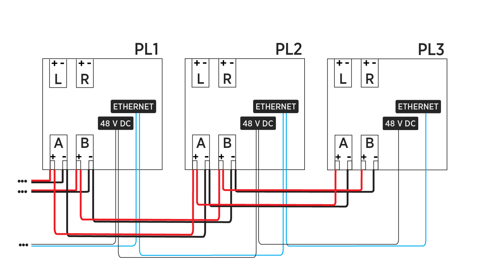
In turn, for Pantograph Down 2000 applications, the Power Link 2000 can accept high voltage DC input from multiple Power Blocks, as shown in the example below.

The high voltage DC output, Ethernet, and 48 V DC power output from Power Block(s) can be connected from Power Link 2000 to Power Link 2000, enabling higher port counts in specific sequential charging configurations.
Power Link 2000 to Pantograph Configuration
Each Power Link 2000 HV DC![]() High Voltage Direct Current output connects to one pantograph. One PD Controller is required for each pantograph. The PD Controller requires 48 V DC and Ethernet connectivity from the Power Link 2000 as well as single-phase AC power from the site. The PD Controller connects to the status LED, Wi-Fi
High Voltage Direct Current output connects to one pantograph. One PD Controller is required for each pantograph. The PD Controller requires 48 V DC and Ethernet connectivity from the Power Link 2000 as well as single-phase AC power from the site. The PD Controller connects to the status LED, Wi-Fi![]() Wireless Fidelity antenna, and RFID
Wireless Fidelity antenna, and RFID![]() Radio Frequency IDentification antenna. The PD Controller also connects to the pantograph for control pilot, actuation commands, and other pantograph functions. The block diagram below illustrates the connectivity between a Power Link 2000 and a pantograph/PD Controller pair.
Radio Frequency IDentification antenna. The PD Controller also connects to the pantograph for control pilot, actuation commands, and other pantograph functions. The block diagram below illustrates the connectivity between a Power Link 2000 and a pantograph/PD Controller pair.

-
Power Link 2000 HV DC
High Voltage Direct Current output to pantograph -
Ethernet connection between Power Link 2000 and PD Controller
-
Power Link 2000 48 V DC output to PD Controller
-
PD Controller 120-277 V AC power input
-
RF connection from PD Controller to Wi-Fi
Wireless Fidelity antenna and RFID Radio Frequency IDentification antenna -
24 V DC connection from PD Controller to pantograph and status LED
Pantographs
Pantograph Down 2000 integrates with the following pantographs:

Schunk SLS 201.102 - High power charging, fast actuation pantograph. Suitable for mount from a ceiling, gantry, or mast.
Safety Warning
- Ensure the pantograph is installed in a location free from safety hazards and restrict access to the movement area with appropriate safety measures.
- Inspect the equipment regularly for mechanical damage and address any issues promptly.
- The pantograph moves quickly and has pinch points.
- To avoid serious injury, keep clear of the moving pantograph and ensure bystanders maintain a safe distance.
- Never reach into the mechanism or touch the moving pantograph.
- No one is allowed underneath the equipment during operation.
Express Plus Guides
Pantograph Down 2000 is a part of the Express Plus product family.
Access documents at ChargePoint Product Reference Documentation.
|
Document |
Content |
Primary Audiences |
|
Datasheet |
Full station specifications |
Site designer, installer, and station owner |
|
Site Design Guide |
Civil, mechanical, and electrical guidelines to scope and construct the site |
Site designer or engineer of record |
|
Concrete Mounting Template Guide |
Instructions to embed the charging station template in a concrete pad with anchor bolts and conduit placement (these may also be included in the Site Design Guide) |
Site construction contractor |
|
Surface Conduit Entry Kit Guide |
Instructions for sites where conduit cannot be run underground |
Installer |
|
Construction Signoff Form |
Checklists used by contractors to ensure the site is correctly completed and ready for product installation |
Site construction contractor |
|
Installation Guide |
Anchoring, wiring, and powering on |
Installer |
|
Operation and Maintenance Guide |
Operation and preventive maintenance information |
Station owner, facility manager, and technician |
|
Service Guide |
Component replacement procedures, including optional components |
Service technician |
|
Declaration of Conformity |
Statement of conformity with directives |
Purchasers and public |
