Install Power Hub
This section describes how to install Power Hub.
Warranty Limitation
-
If the distribution cabinet is not installed and serviced by a ChargePoint certified installer or technician using a ChargePoint-approved method, the product is excluded from all ChargePoint and other warranties and ChargePoint is not responsible.
-
You must be a licensed electrician and complete the training at https://www.chargepoint.com/partners/training-certification to become ChargePoint certified and to access the ChargePoint Platform.
Alternatively, you may use a forklift bracket kit, or a crane with lifting shackles and a spreader bar (constraints may differ among sites).
In addition to these instructions, installers must reference the specific site scope and project drawings for additional information and considerations, including the system layout and any related electrical drawings.
Install Second Input Kit (As Required)
Refer to the site design drawings. If the Power Hub connects to two Power Blocks, install a Second Input Kit into the Power Hub while it is still mounted on its shipping pallet. See Appendix: Install Second Input Kit for installation instructions.
Prepare for Mount
To prepare the mount, complete the following steps:
-
Remove plastic caps from anchor bolts.
-
If the installation utilizes stub-up conduit entry, remove the gland plate.
-
Remove the gland plate fasteners (x8).
-
Remove the gland plate from cabinet.
-
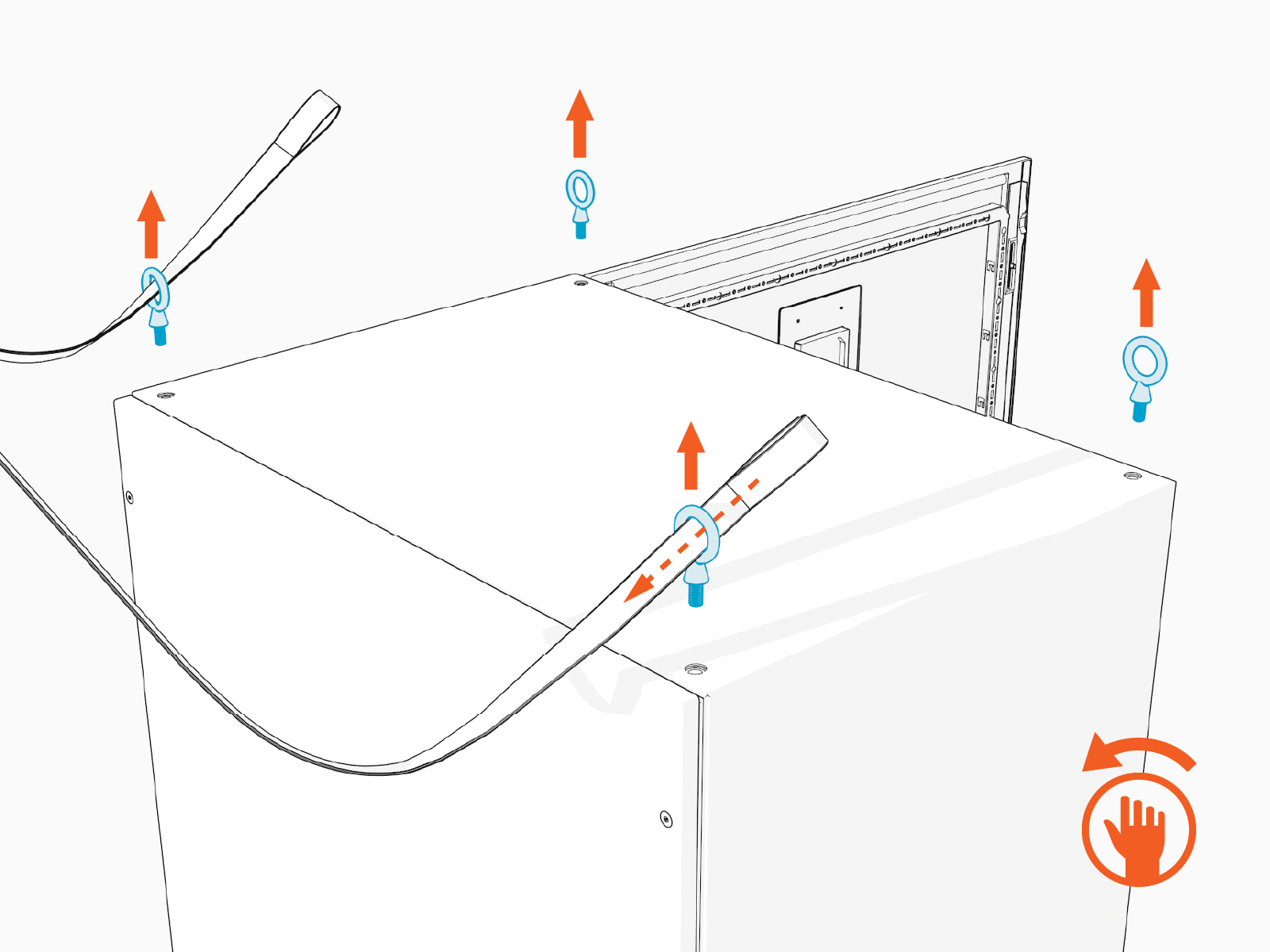
Remove the exterior top bolts (x4). Store the bolts for later reuse.
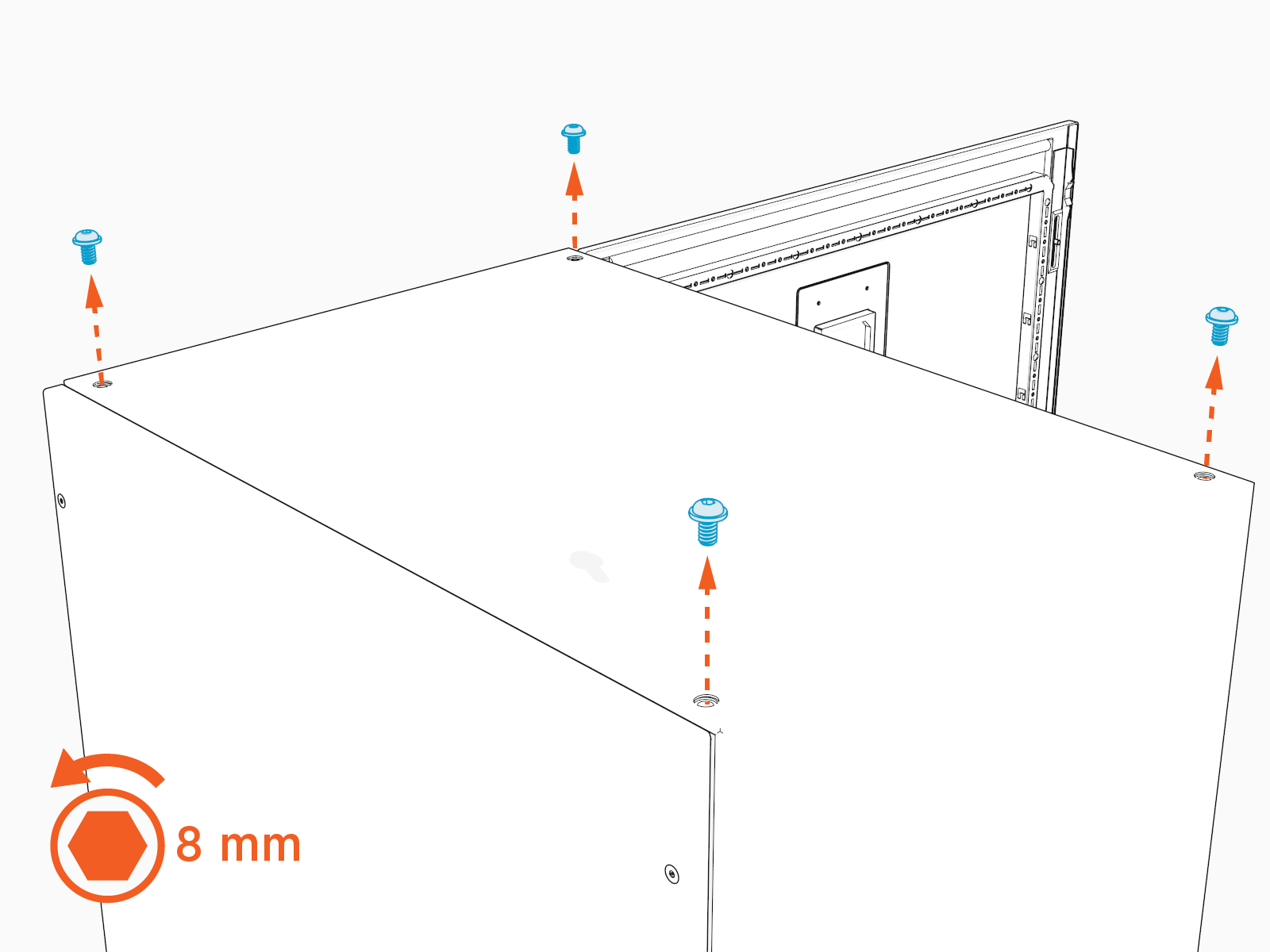
-
Install the eye bolts (x4) into the top of the cabinet. Hand tighten.
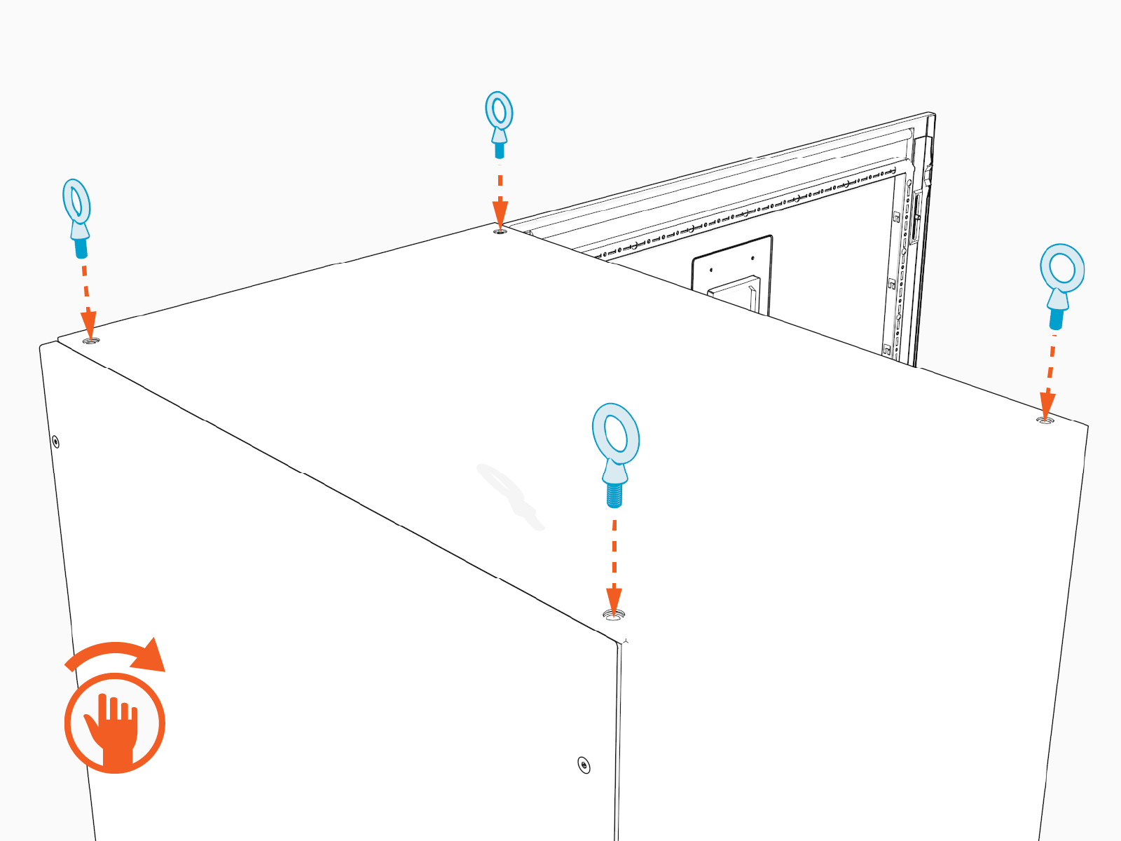
-
If the Power Hub requires a riser, assemble and install a Riser Kit. See Appendix: Install Riser Kit. Otherwise, proceed directly to the next section.
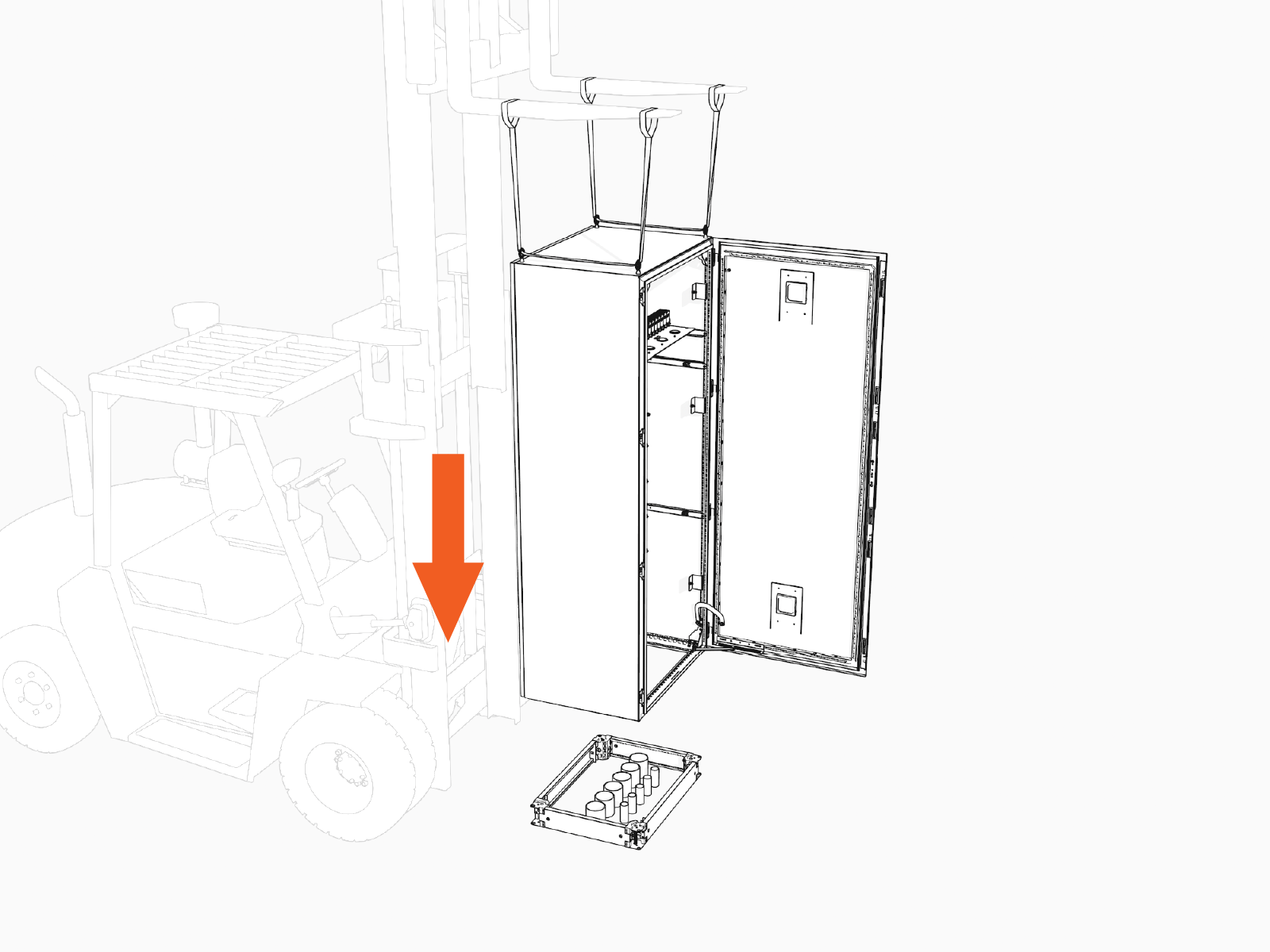
Mount Cabinet Direct to Pad
To mount the cabinet direct to pad, complete the following steps:
-
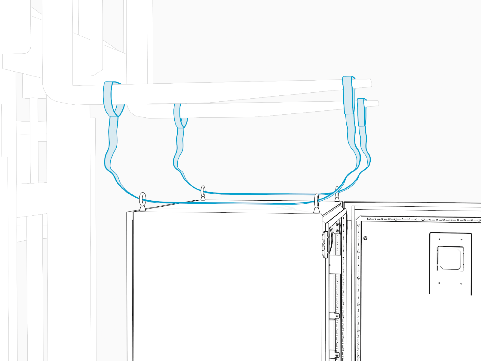
Thread the lifting slings through the eye bolts. Position the forklift tines over the Power Hub. Slide the sling eye loops over the tines. Keep the straps slack.
-
Remove nuts (x4) and washers (x4) from pallet bolts.
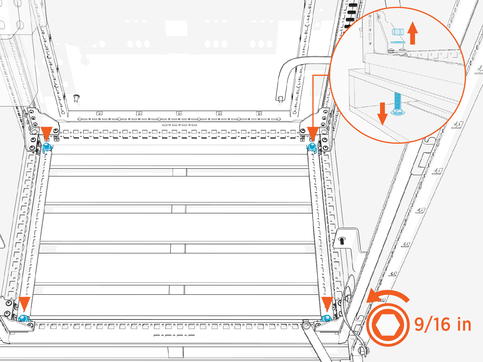
-
Use the forklift to carefully lift the Power Hub off the pallet. Position the Power Hub over the installation site.
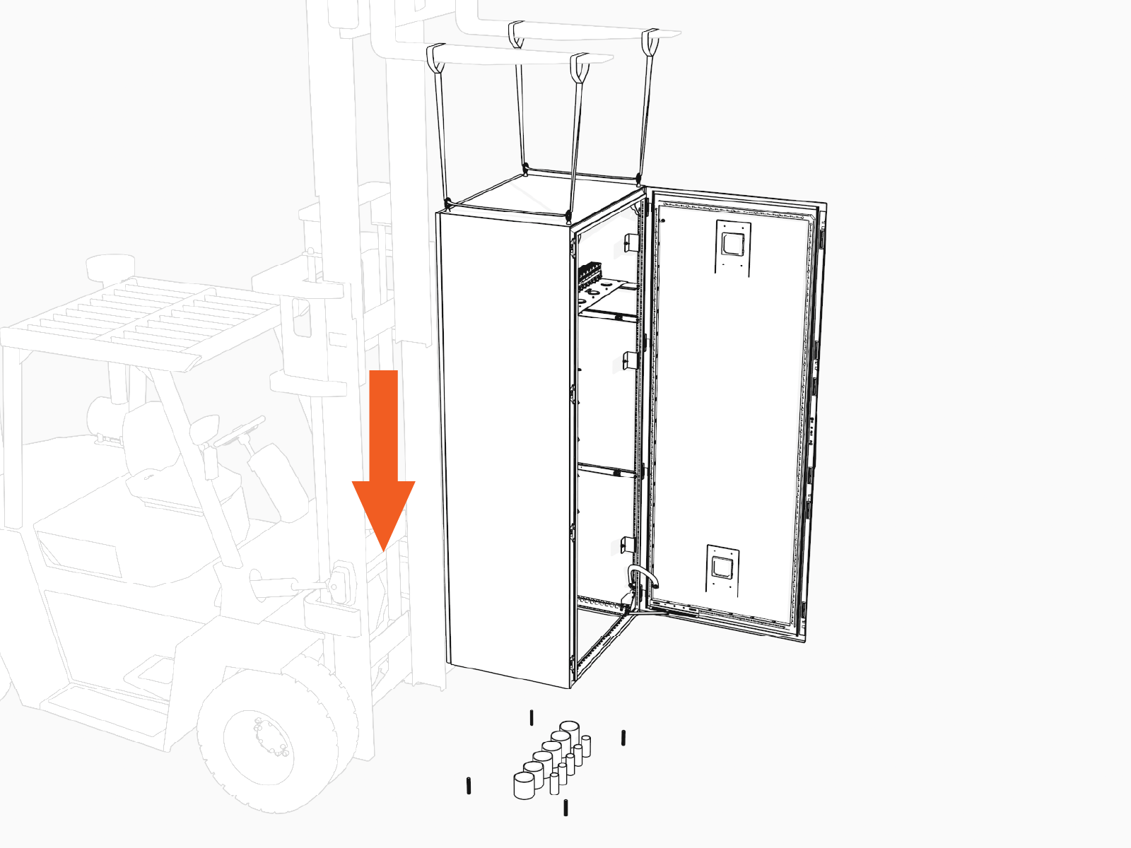
-
Slowly lower the Power Hub while aligning the cabinet anchor holes over the anchor bolts.
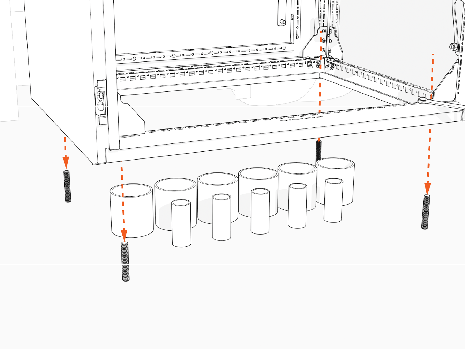
-
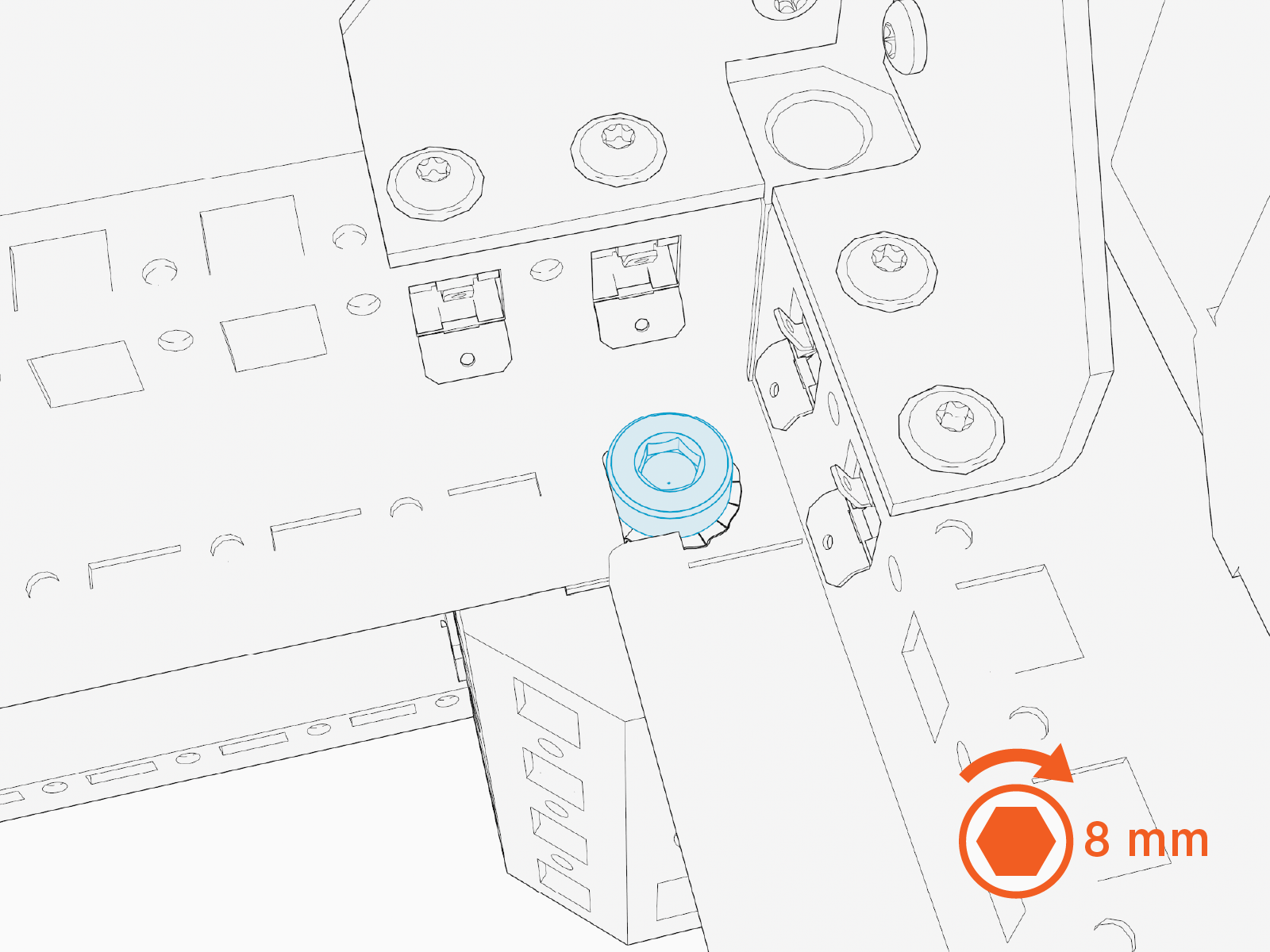
Install washer (x4) and top nut (x4) onto each of the anchor bolts. Hand tighten.
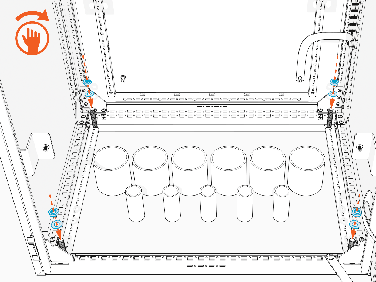
-
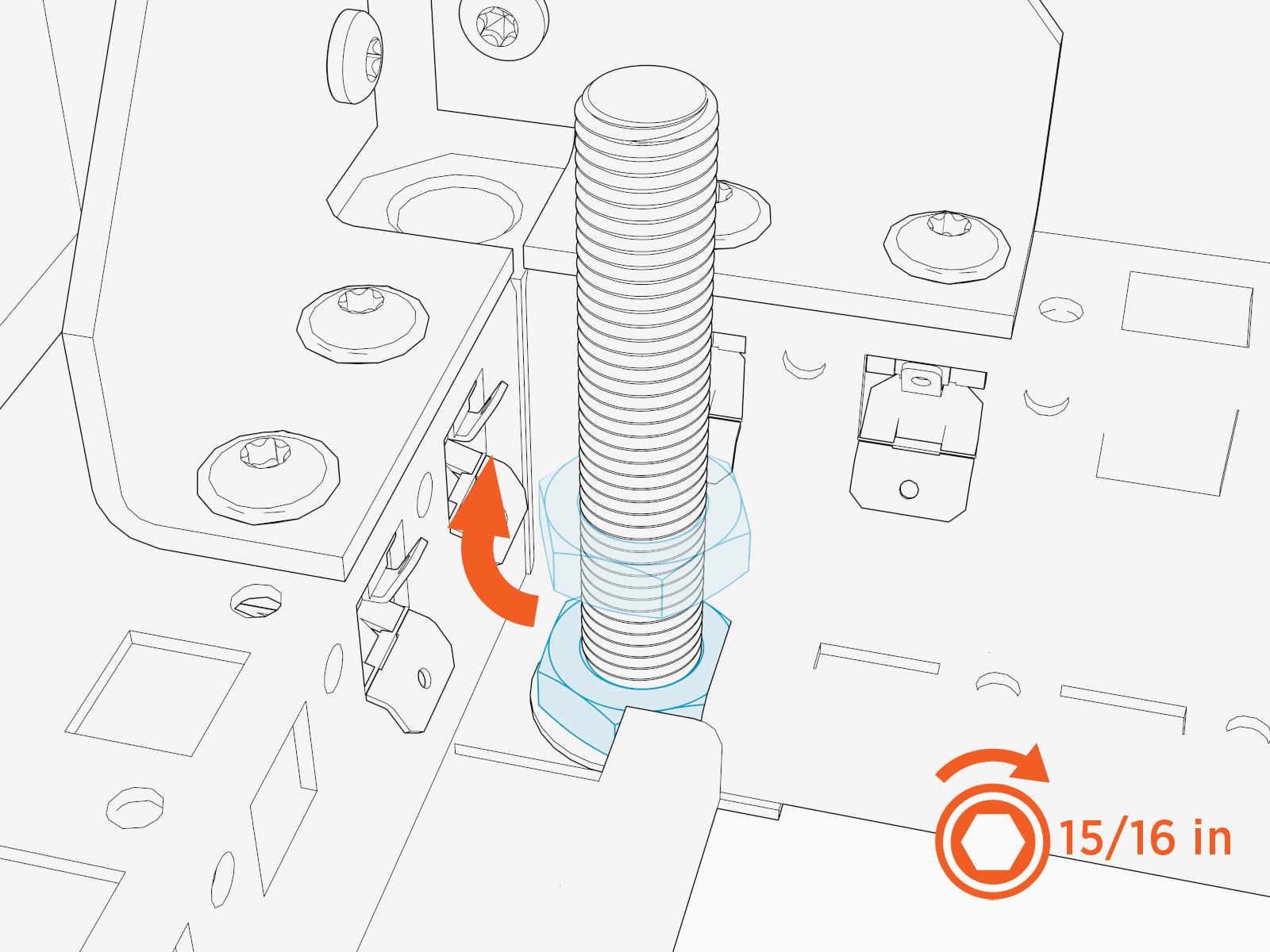
Torque top nuts (x4) to 94.9 Nm (70 ft-lb).
-
This concludes Power Hub mount direct to the pad. Proceed to Complete the Mount.
Mount Cabinet on a Riser
To mount the cabinet on a riser, complete the following steps:
-
Thread the lifting slings through the eye bolts. Position the forklift tines over the Power Hub. Slide the sling eye loops over the tines. Keep the straps slack.
-
Remove nuts (x4) from pallet bolts.
-
Use the forklift to carefully lift the Power Hub off the pallet. Position the Power Hub over the installation site.
-
Slowly lower the Power Hub onto the riser. Align the cabinet anchor holes with the threaded holes on the riser.
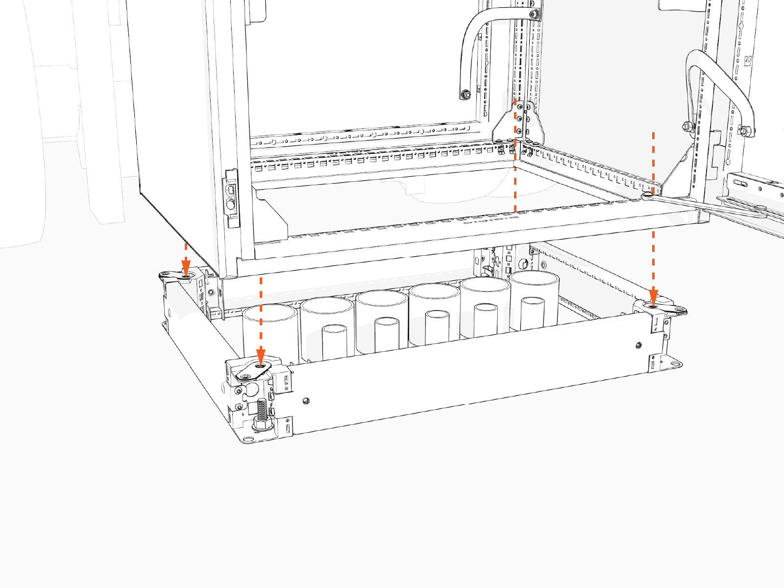
-
Install M12 bolts (x4) with toothed washers (x4) through the Power Hub anchor holes into the threaded holes on the riser. Hand tighten.
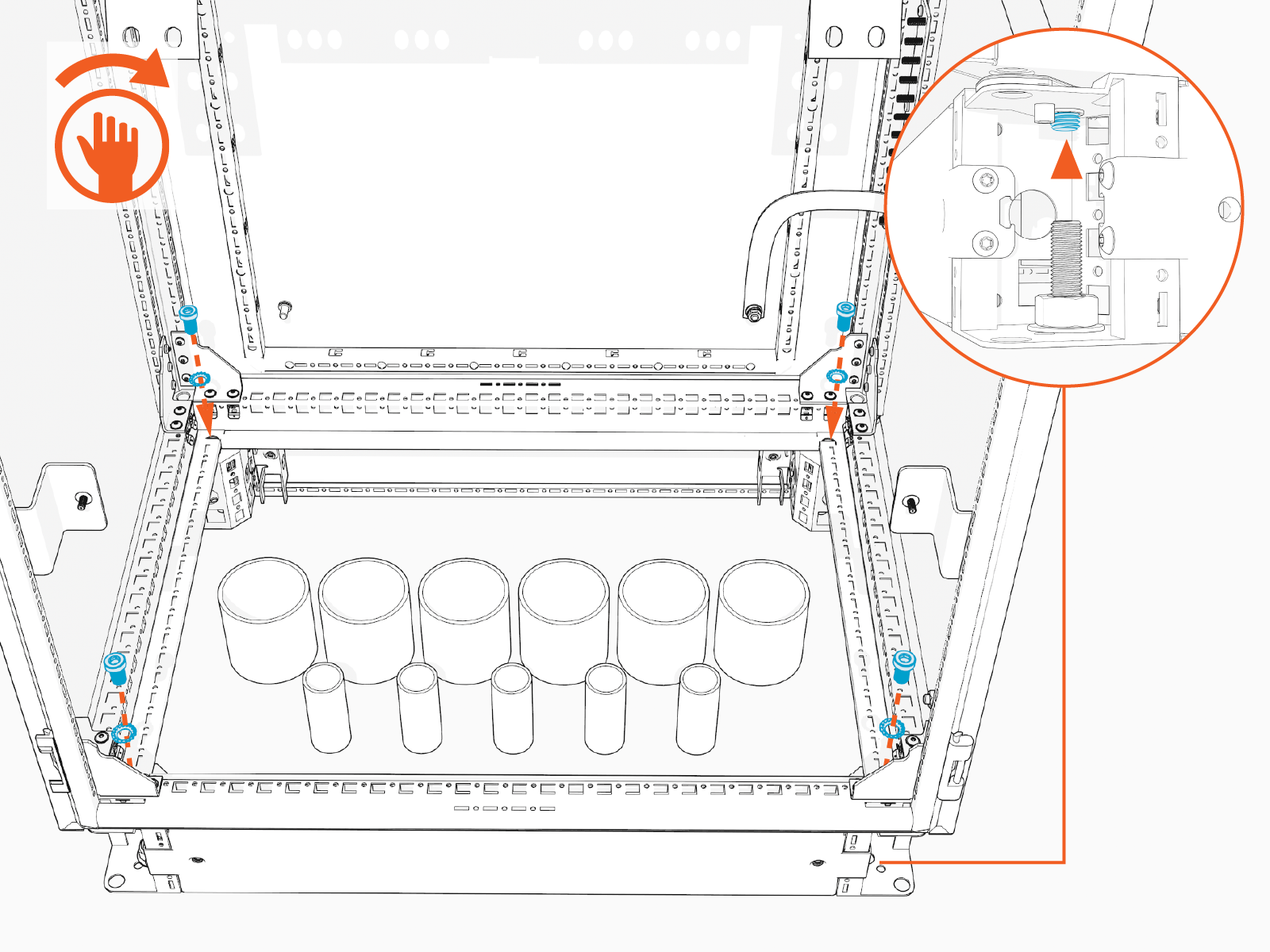
-
Torque bolts (x4) to 94.9 Nm (70 ft-lb).
-
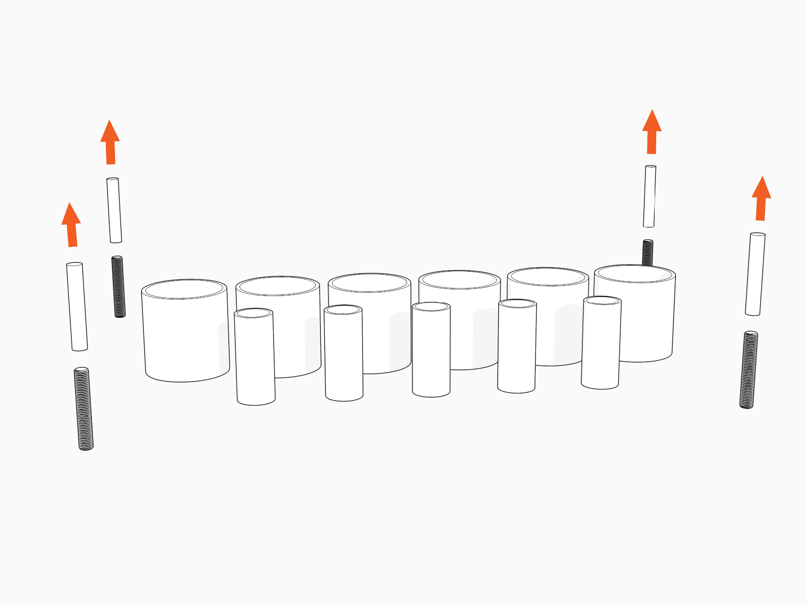
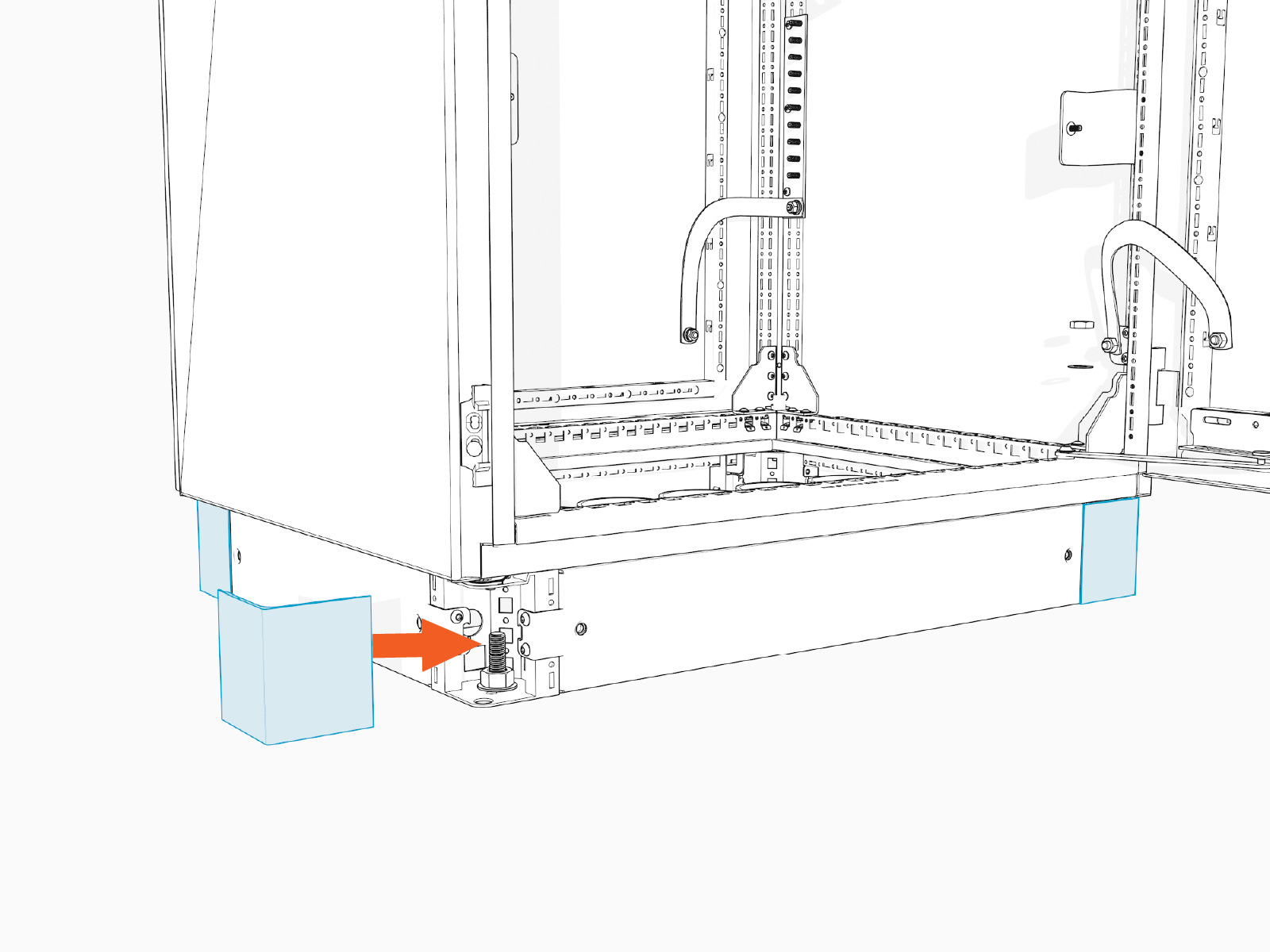
Install covers (x4) at each corner of the riser.
Complete the Mount
To complete the mount, follow the instructions below:
-
Release and remove the lifting slings. Remove the eye bolts.
-
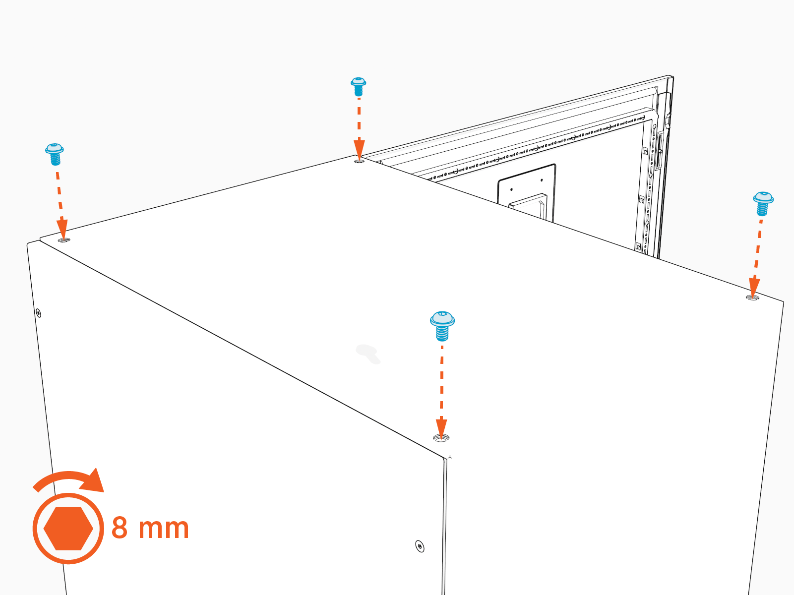
Reinstall the top bolts. Hand tighten the bolts.
-
Drill a weep hole with diameter 3.2–6.4 mm (1/8–1/4 in) into the lowest part of the Power Hub at its walls, to allow water to drain out of the enclosure.
-
Vacuum all debris from the bottom of the cabinet.
-
Install conduit fittings and gland plate, as applicable:
-
If called for by the site design plan, install conduit fittings into the gland plate and then reinstall gland plate. Torque gland plate T25 torx screws (x8) to 5.1 Nm (45 in-lb).
-
If called for by the site design plan, install conduit fittings into cabinet wall for surface conduit entry.
-
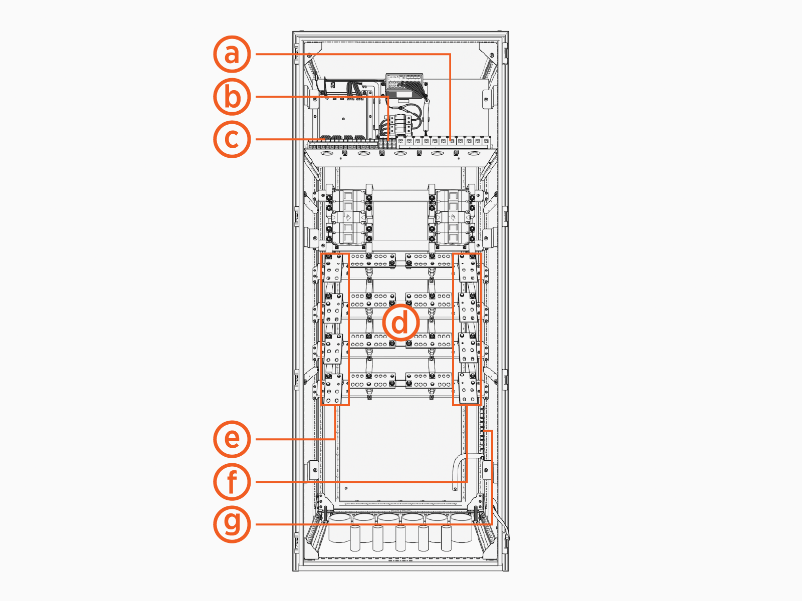
Wire Landing Locations
Review all wire landing locations.
-
Ethernet ports, all ports equivalent
-
48 V DC input terminals, LV1 (+/-) and LV2 (+/-)
-
48 V DC output terminals, PL1 (+/-) through PL8 (+/-)
-
High voltage DC output terminals, A1 (+/-) through A4 (+/-) and B1 (+/-) through B4 (+/-)
-
High voltage DC input terminals left, Input A (+/-) Left and Input B (+/-) Left
-
High voltage DC input terminals right, Input A (+/-) Right and Input B (+/-) Right
-
Ground studs
These terminals are absent if the Power Hub connects to only one Power Block.
Split the Buses (As Needed)
To split the buses, complete the following steps:
-
Consult the site plan to determine if the Power Hub requires a split bus configuration. If not, skip this section and proceed to Pull and Connect Wires.
-
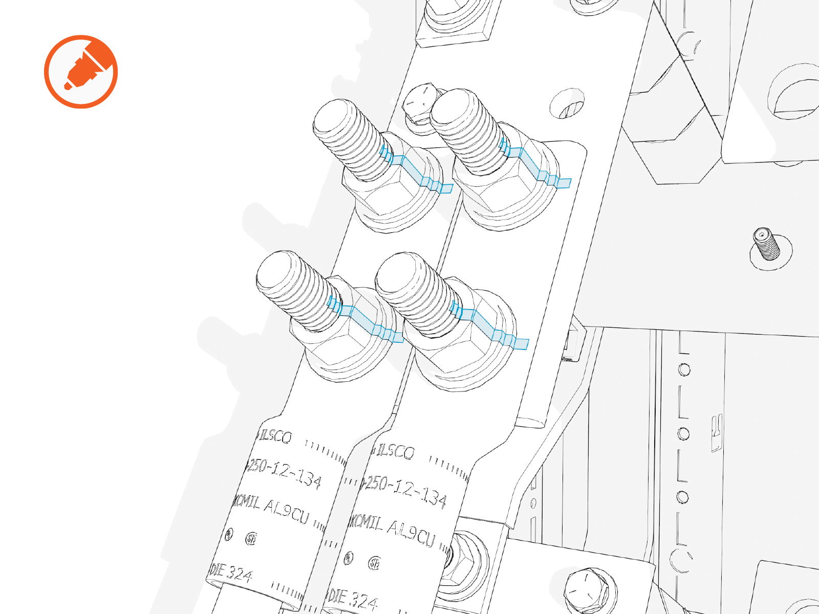
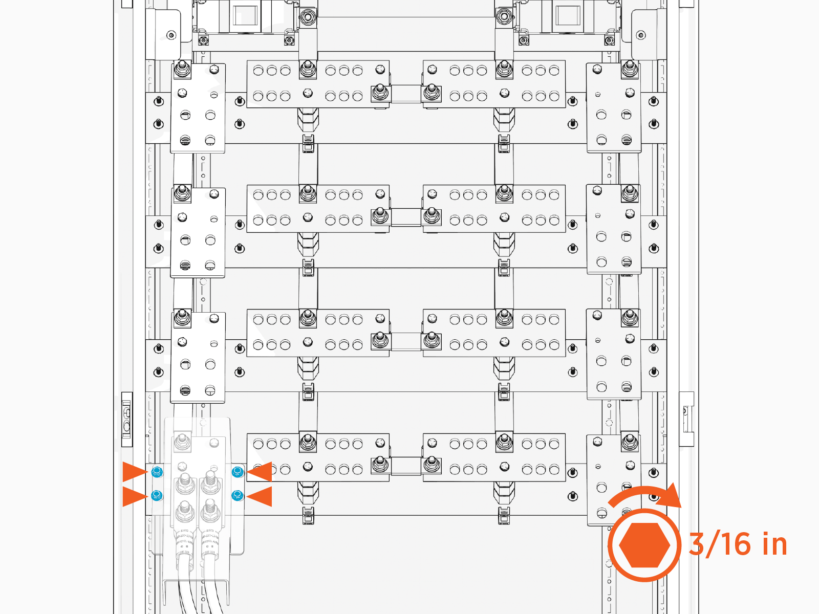
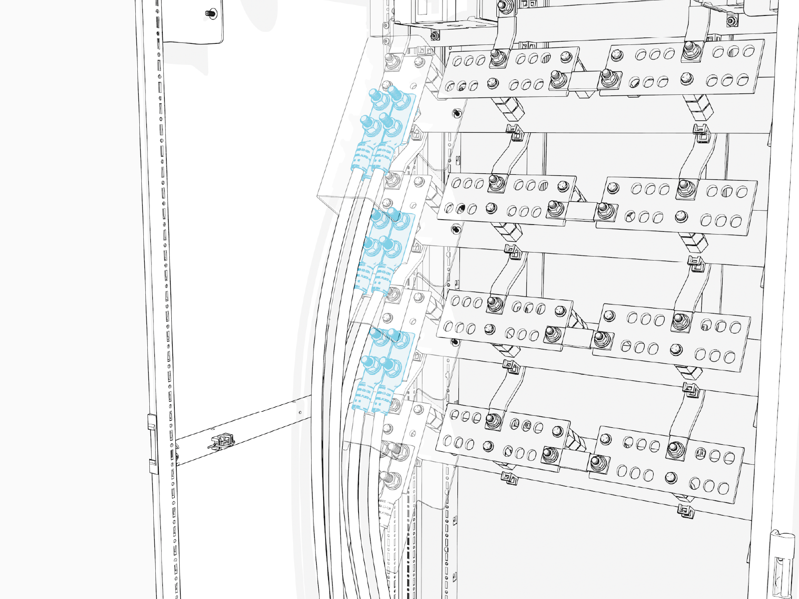
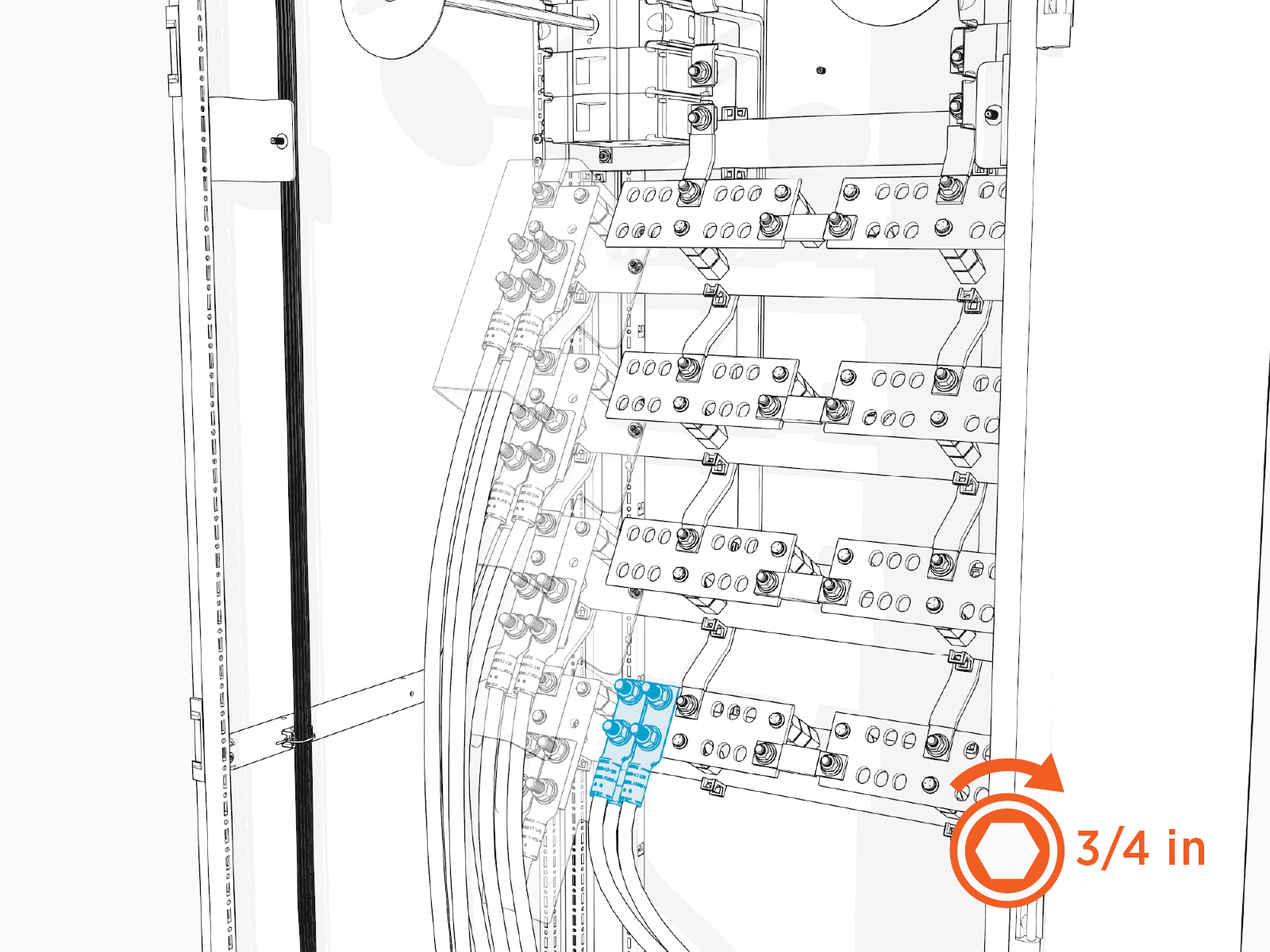
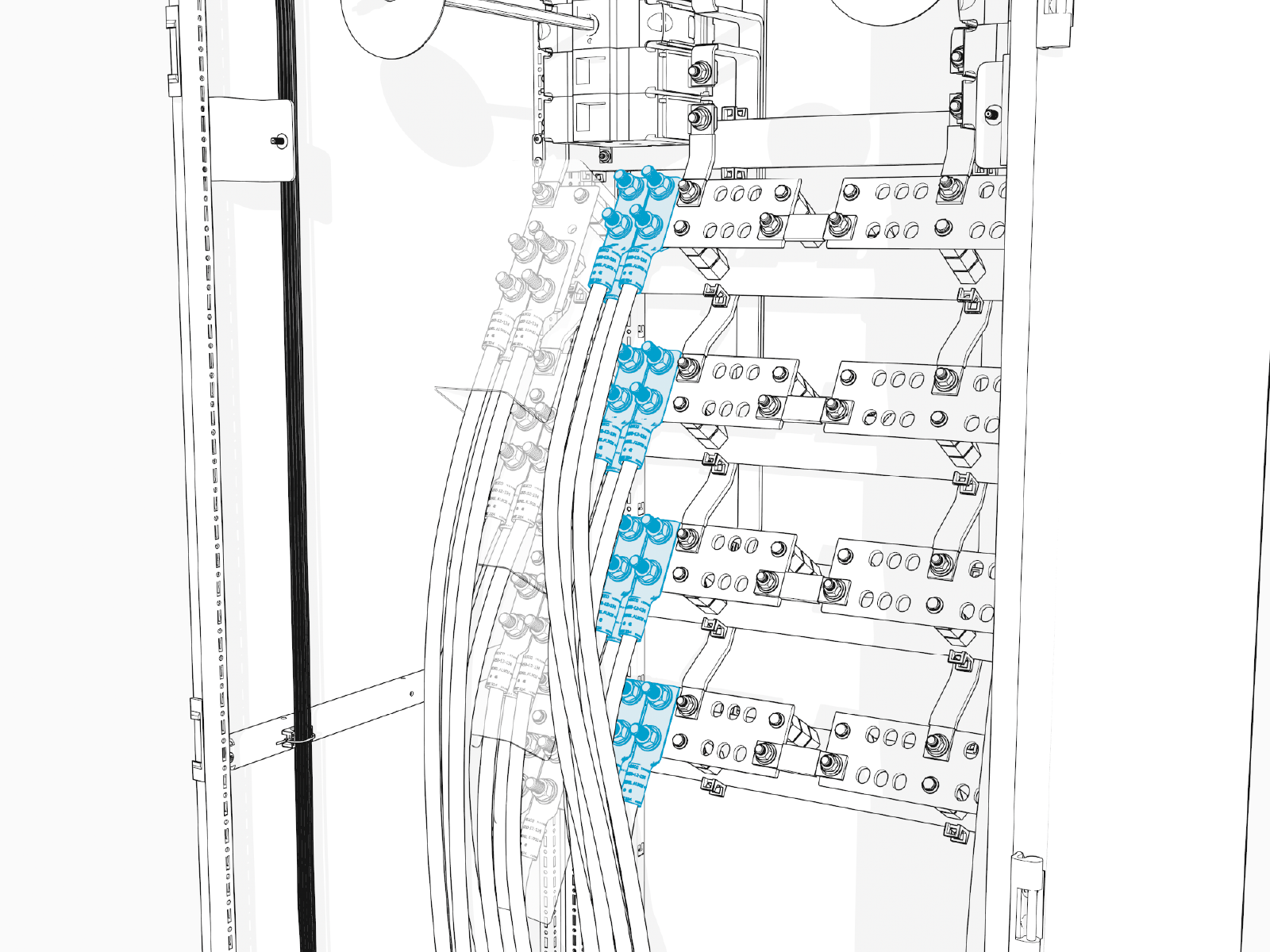
Locate the bus jumpers (x4) at the high voltage DC output terminals. Each jumper is secured with two bolts.
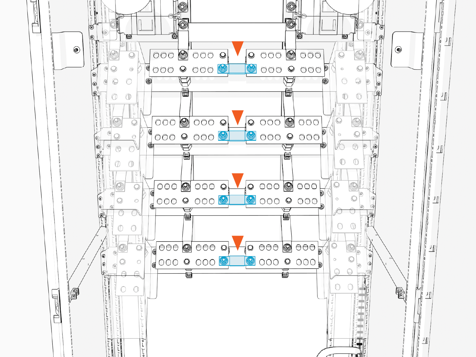
-
Use a socket wrench to remove all four bus jumpers.
All four bus jumpers must be removed. Do not remove a partial set of bus jumpers.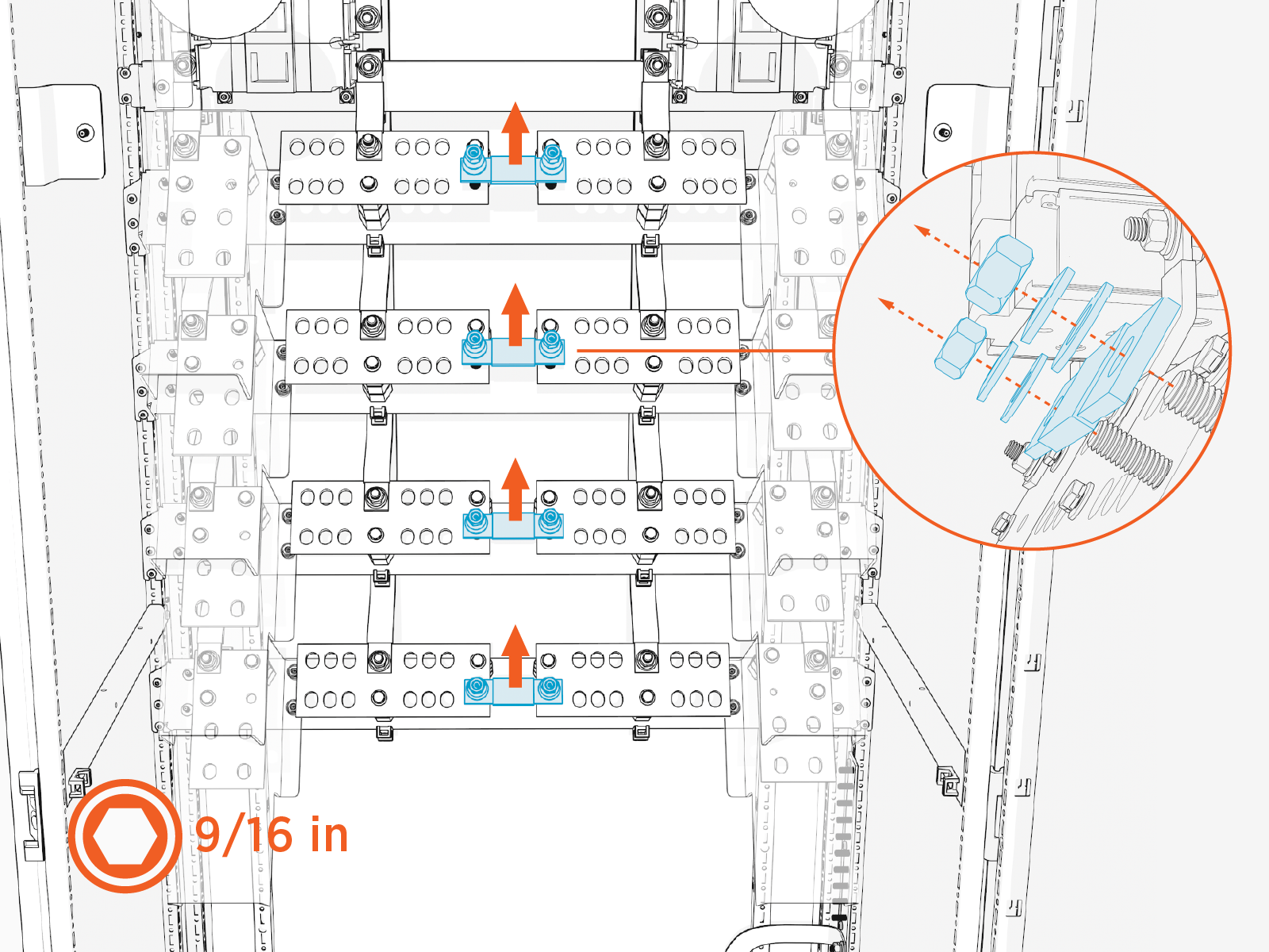
Pull and Connect Wires
Follow instructions in this section to pull and connect wires. Wires may be pulled and connected in any order, but the following practices are recommended for an orderly install:
-
Pull and connect one set of wires before pulling in another set of wires.
-
Pull and connect wires from rear-most conduits first.
-
Connect ground wires before connecting high voltage DC output wires. Once the high voltage DC wires are connected, there may be limited access to the ground wire terminals.
There are many possible wire configurations for the Power Hub. Illustrations in this guide depict one of many wiring configurations, and may not represent the wiring configuration specific to your project.
High Voltage DC and Ground Wires
To pull and connect high voltage DC and ground wires, perform the steps given below.
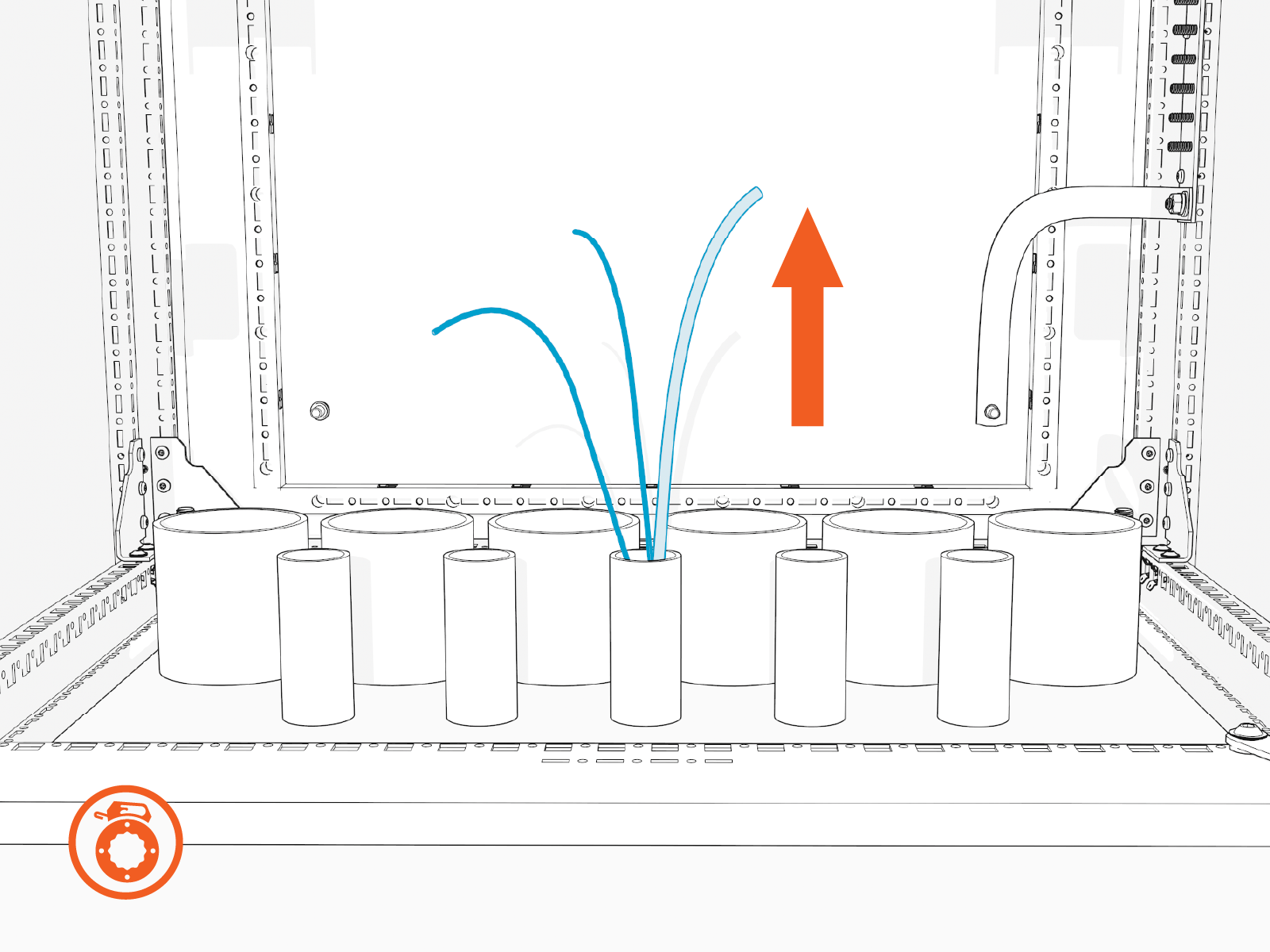
Pull Wires
-
Label the high voltage DC and ground wires at both ends.
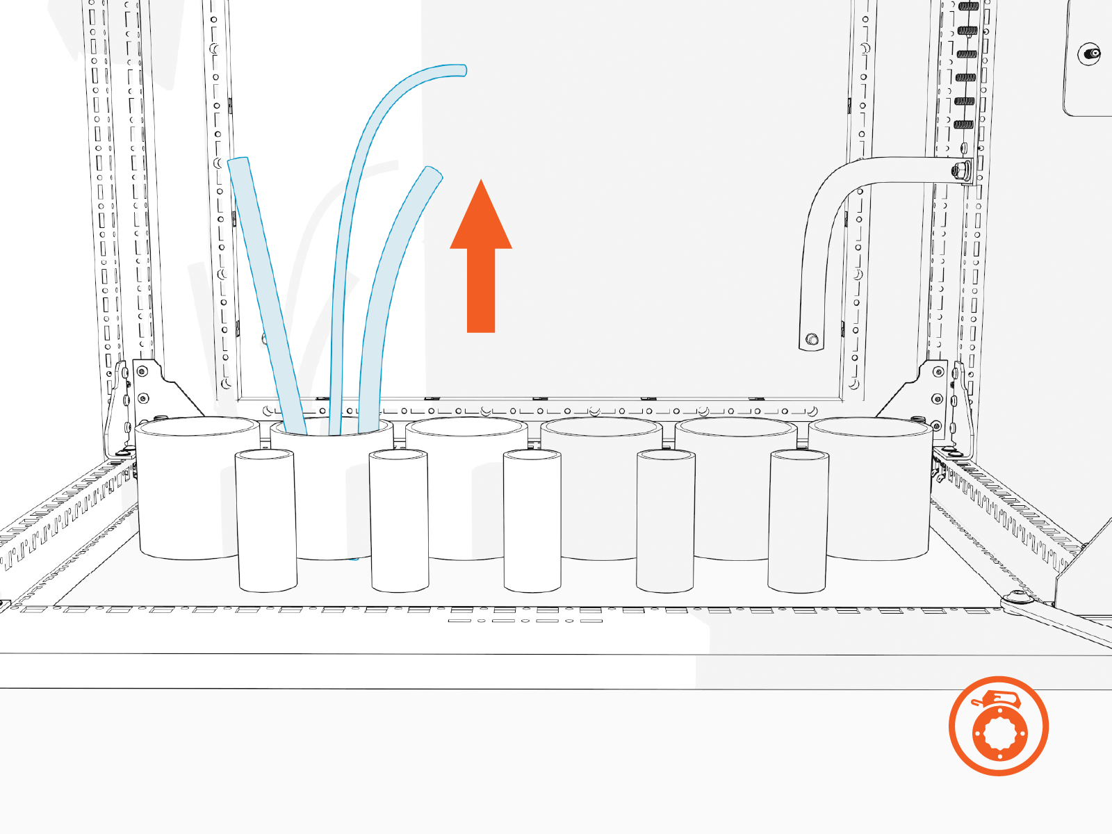
-
Use a cable puller or fish tape to pull the high voltage DC and ground wires through the conduits. If necessary, use a non-conductive wire pulling lubricant to facilitate the pull.
-
Wipe off any remains of wire pulling lubricant if applied while pulling the wires. Use paper towel.
-
Perform conductor insulation test on the high voltage DC wires. Have the results ready to provide upon request.
Measure and Cut High Voltage DC Input Wires
In this stage of the installation, lugs (with no wires attached) are temporarily staged onto the high voltage DC input terminals. They are used to measure and cut the high voltage DC input wires to length. Perform all steps below for each scheduled high voltage DC input wire. See Wire Landing Locations for location of wire landings.
-
Remove the safety shields from all the high voltage DC input terminals. Work your way from the highest shield to the lowest shield. Each shield is held in place by four captive screws that can be loosened by finger or with a hex wrench. Set aside the covers in a safe location.
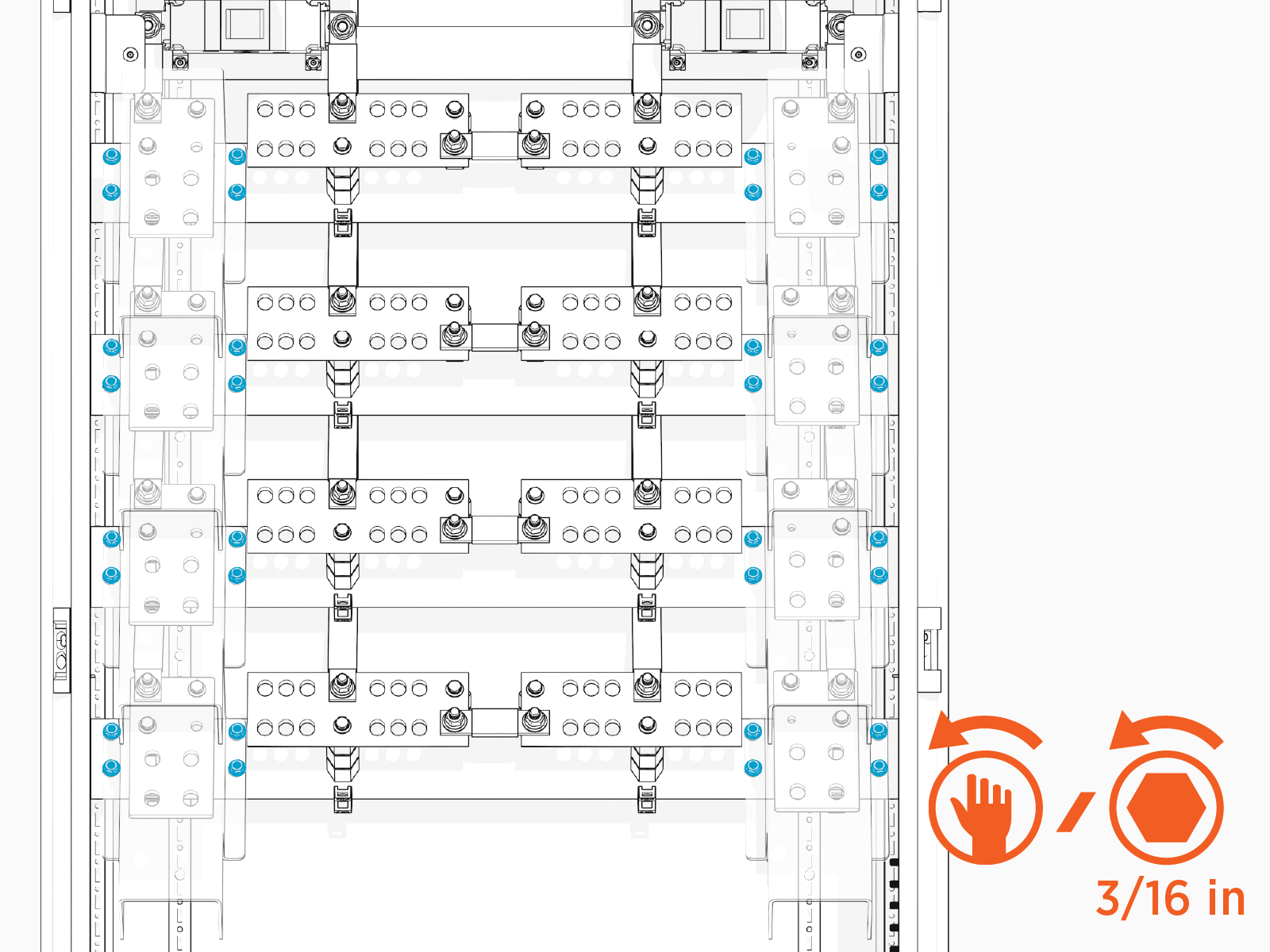
-
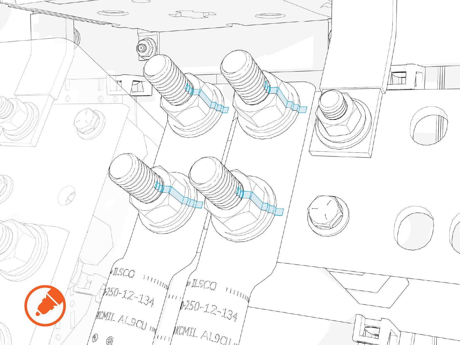
Install lugs without the wires onto the high voltage DC input terminals. Hand tighten.
Two wires can be installed with one set of fasteners, as shown above, with one wire on top of the terminal and one wire beneath the terminal.
-
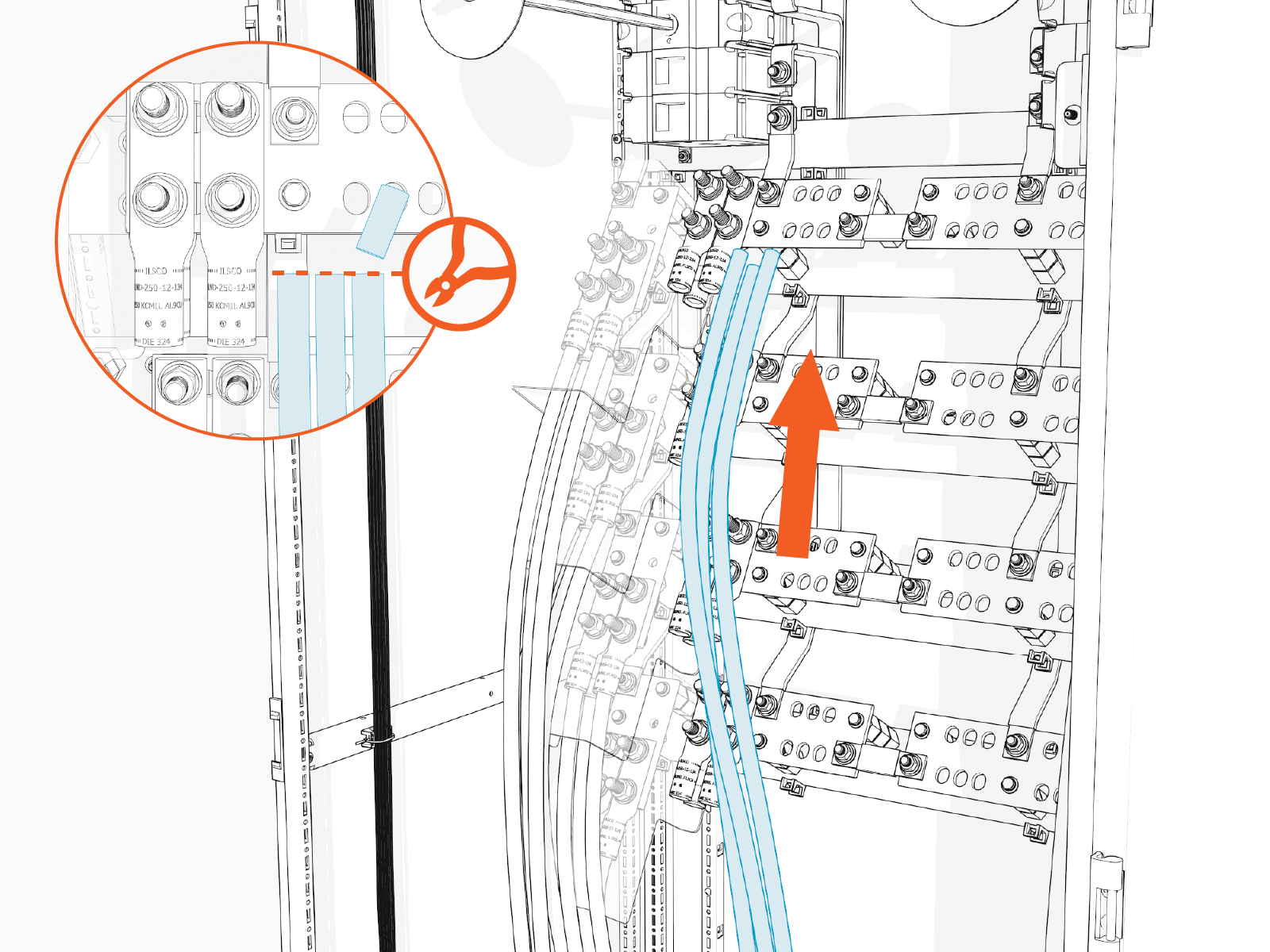
Pull each high voltage DC input wire up to reach its corresponding lug, until the wire end reaches the top of the lug barrel. Cut the wire to length.
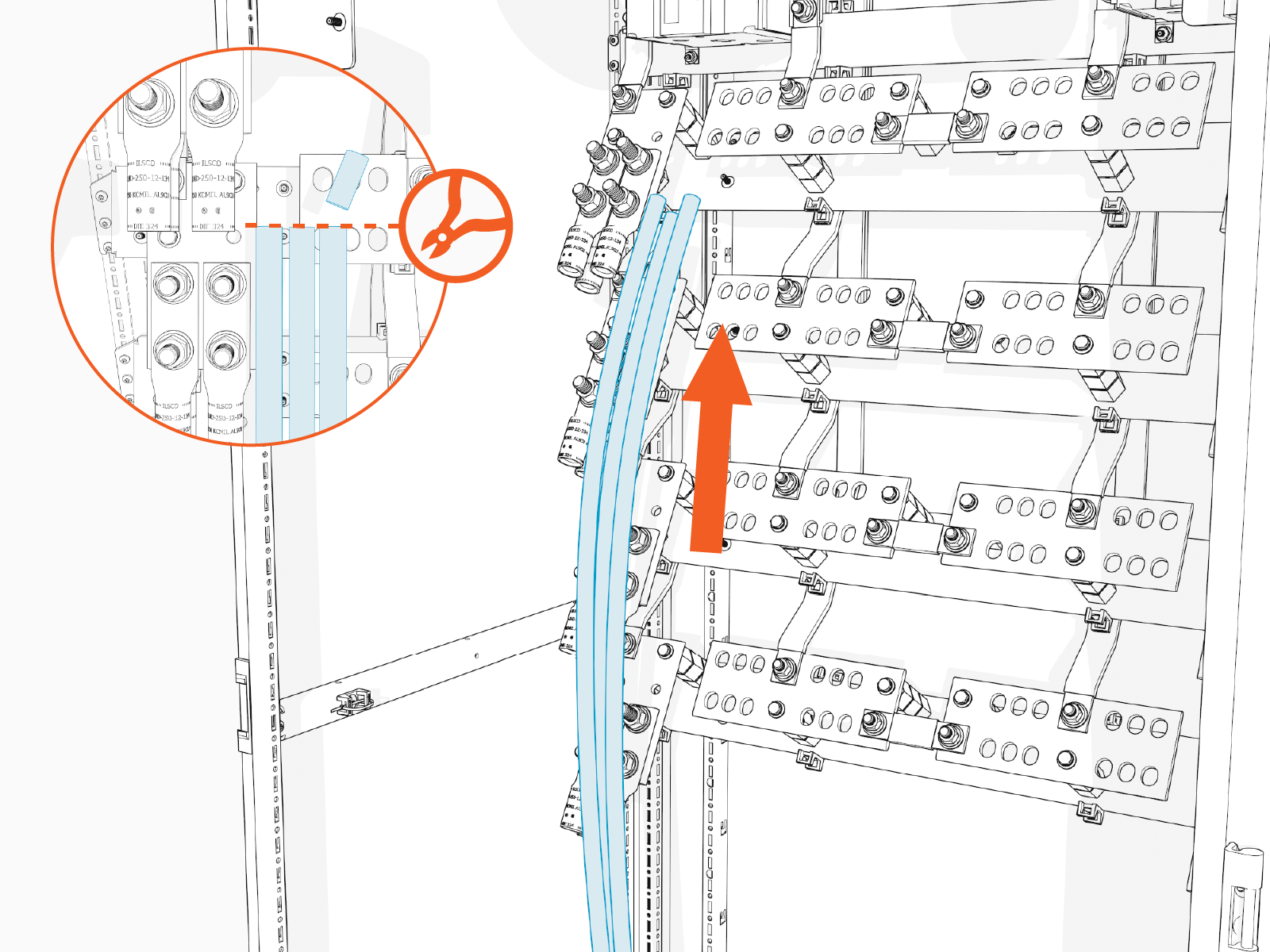
-
Remove the lugs from the terminals.
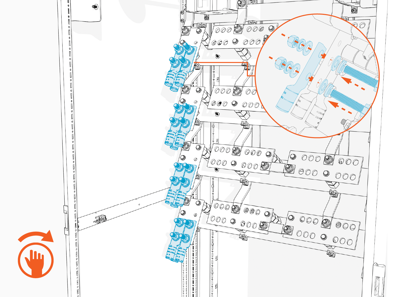
Connect High Voltage DC Input Wires
In this stage of the installation, the high voltage DC input wires are connected to their terminals. Repeat the steps below for each set of wires scheduled to land on a high voltage DC input terminal. See Wire Landing Locations for location of wire landings.
- See Materials for lug specifications.
- Make sure no wire material is exposed below the lug barrel. If necessary, heat shrink or tape the exposed area to meet local code requirements.
- Make the connections starting at the lowest terminal and work upwards.
-
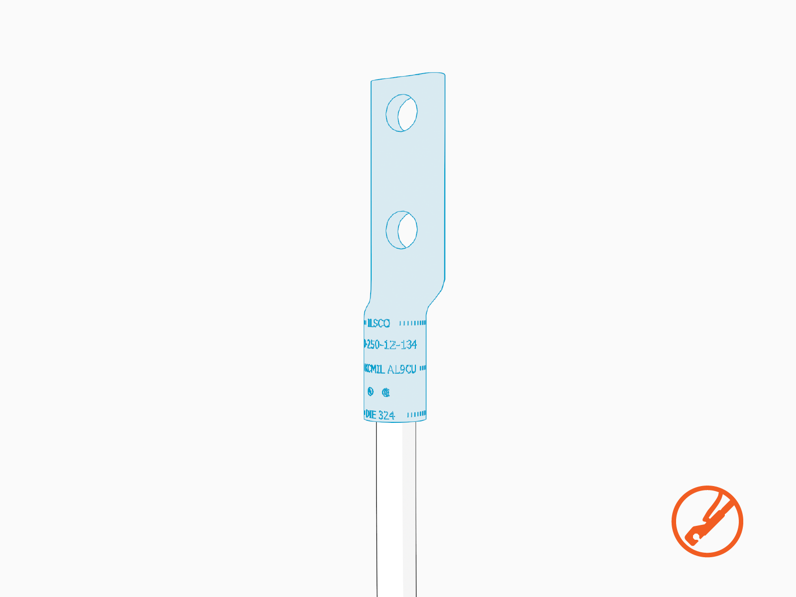
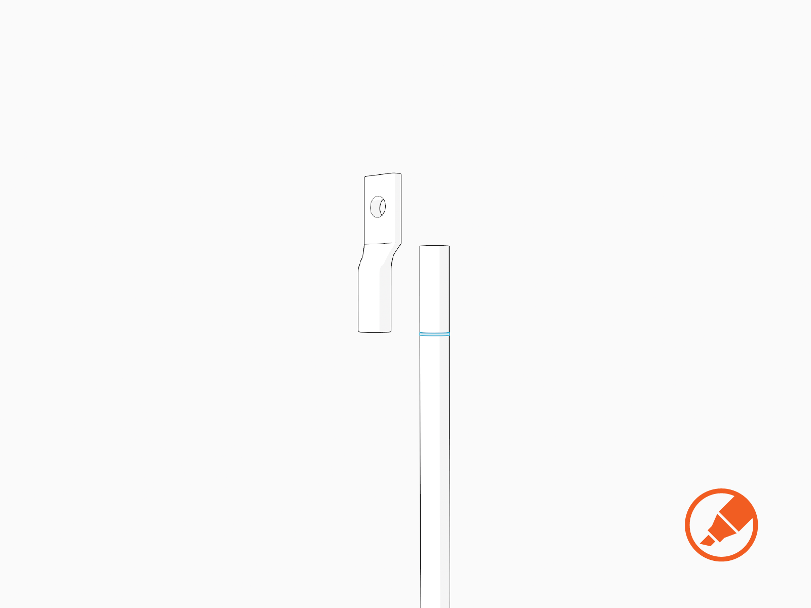
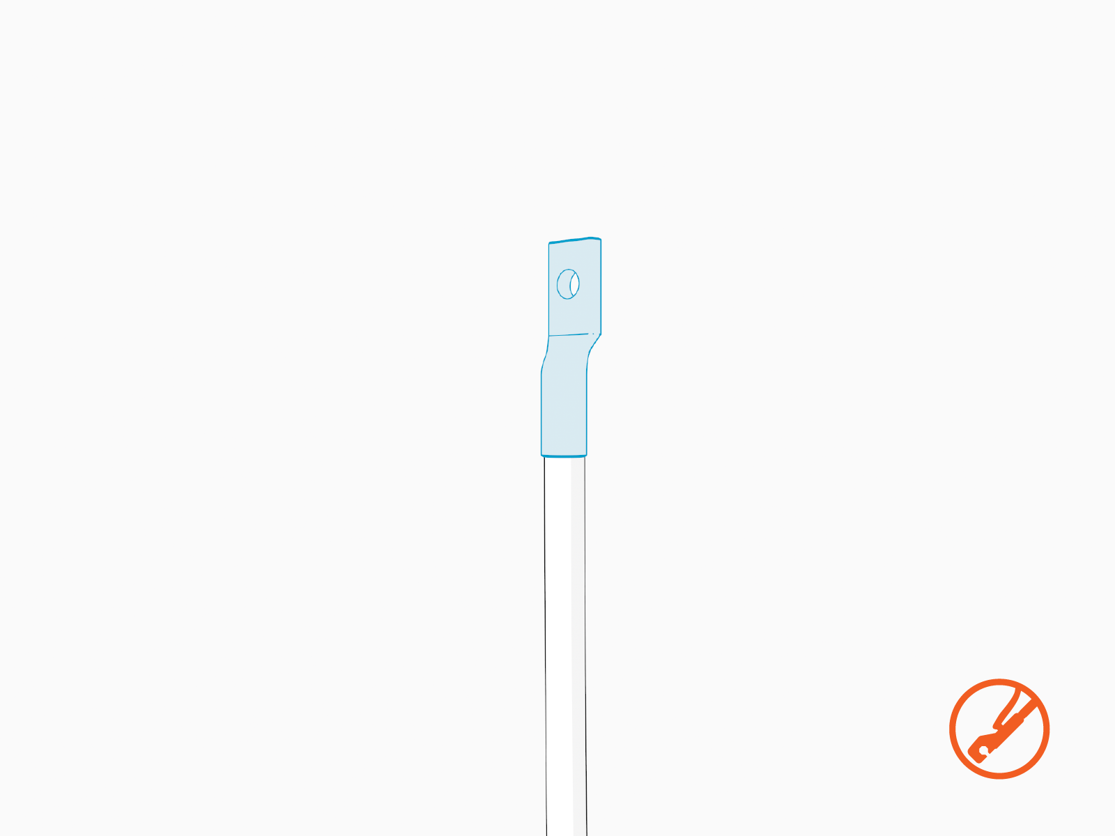
Hold the wire end parallel to a lug, aligning the tip of the wire to the top of a lug barrel. Mark the length of the barrel on the wire.
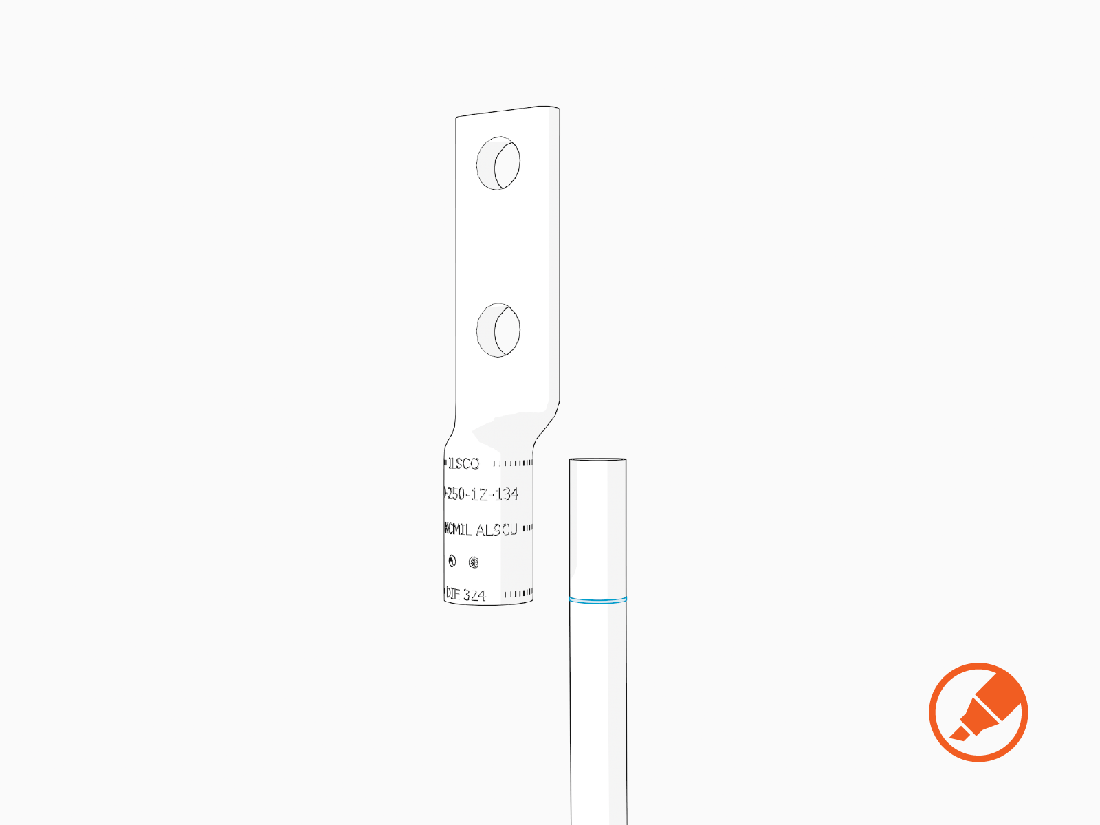
-
Strip the wire to the marked length.

-
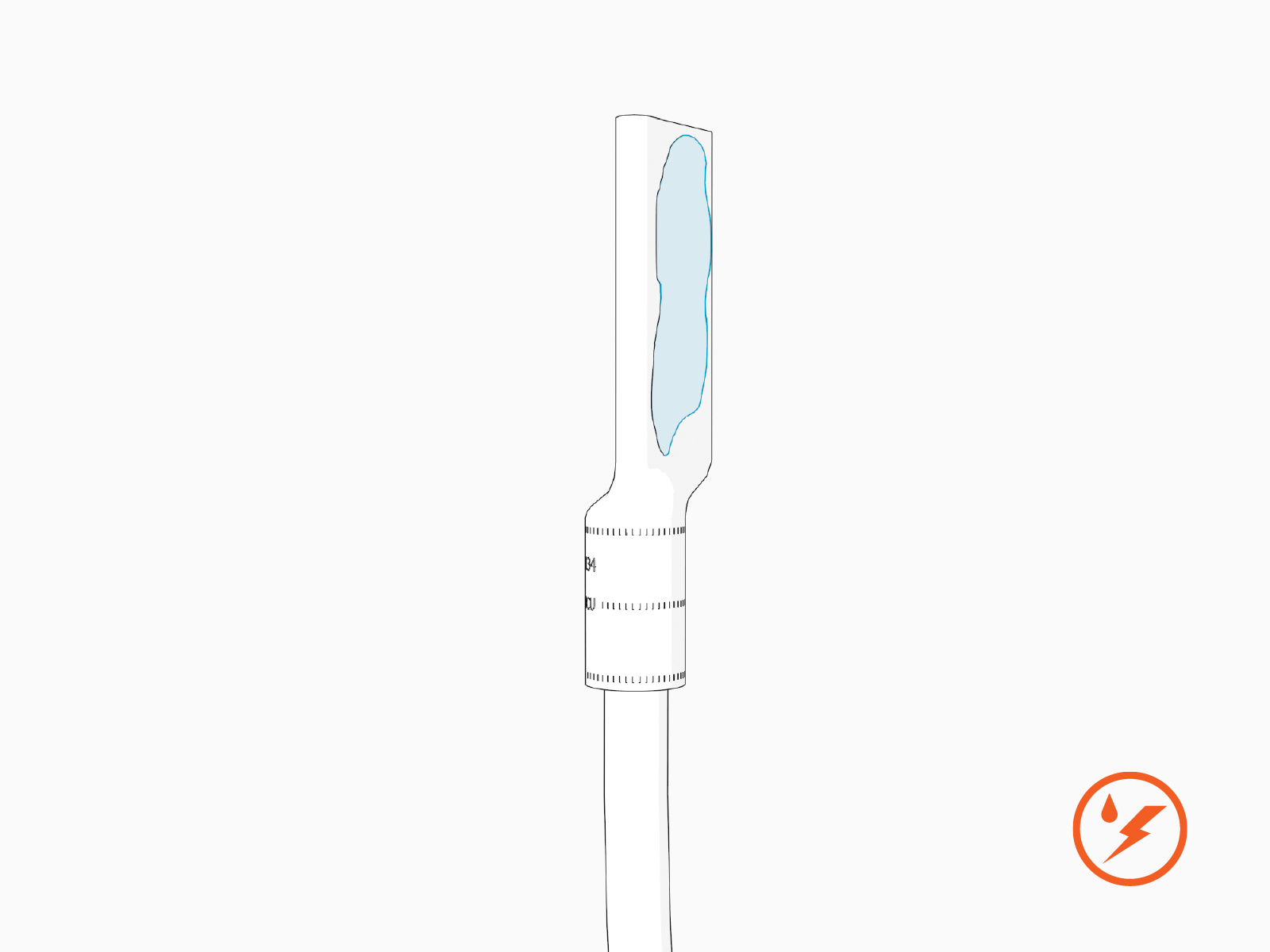
If recommended by the wire manufacturer or local code, apply an anti-oxidant joint compound to the stripped wire end to make a gastight joint with the lug.
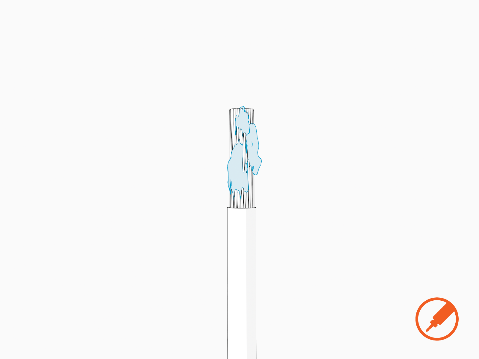
-
Crimp the lug onto the wire.
-
Apply dielectric grease to back of the lug.
-
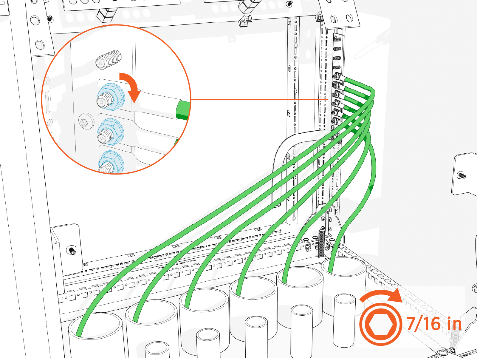
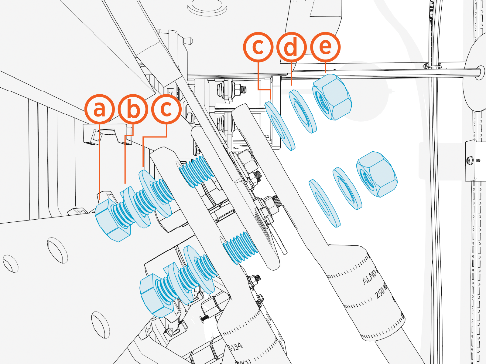
Install the lug onto the high voltage DC input terminal.
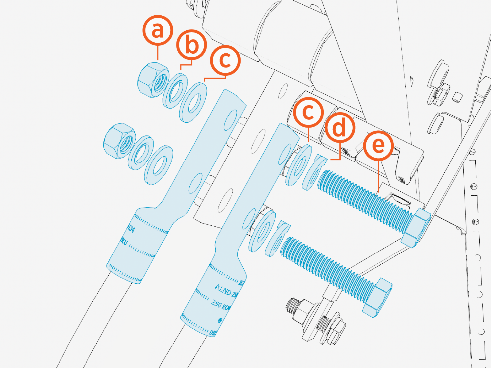
Install the lugs using:
-
1/2 in hex nut
-
1/2 in Belleville washer
-
1/2 in flat washer
-
1/2 in lock washer
-
1/2 x 2-1/4 in bolt
Two wires can be installed with one set of fasteners, as shown above, with one wire on top of the terminal and one wire beneath the terminal.
-
-
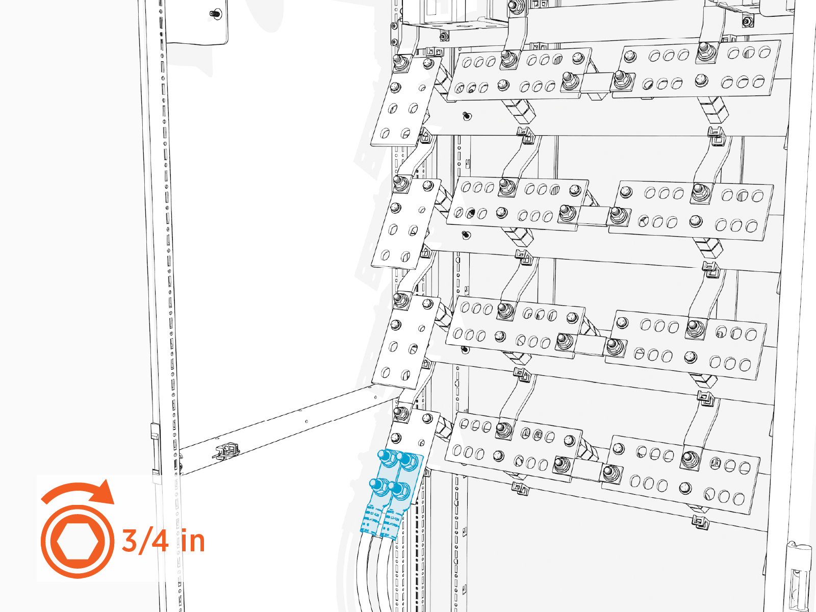
Torque the fasteners to 61.6 Nm (45 ft-lb).
-
Mark all torqued connections.
-
Reinstall the safety shield over the high voltage DC input terminal. Tighten the captive screws (x4 at each shield). Torque to 2.8 Nm (25 in-lb).
-
Repeat for all wire sets landing on the high voltage DC input terminals, working from lowest terminal to highest terminal.
Connect Ground Wires
To connect ground wires, complete the following steps:
- See Materials for lug specifications.
- Make sure no wire material is exposed below the lug barrel. If necessary, heat shrink or tape the exposed area to meet local code requirements.
- Make the connections starting at the lowest terminal and work upwards.
-
For each wire, hold the wire end parallel to a lug, aligning the tip of the wire to the top of a lug barrel. Mark the length of the barrel on the wire.
-
Strip the wires to the marked length.

-
Crimp lugs on the ground wires.
-
Land the ground wires onto the ground studs with 1/4 in nuts. Torque to 4.9 Nm (43 in-lb).
Measure And Cut High Voltage DC Output Wires
In this stage of the installation, lugs (with no wires attached) are temporarily staged onto the high voltage DC output terminals. They are used to measure and cut the high voltage DC output wires to length. Perform all steps below for all scheduled high voltage output wires. See Wire Landing Locations for location of wire landings.
-
Install lugs without the wires onto the high voltage DC output terminals and hand tighten.
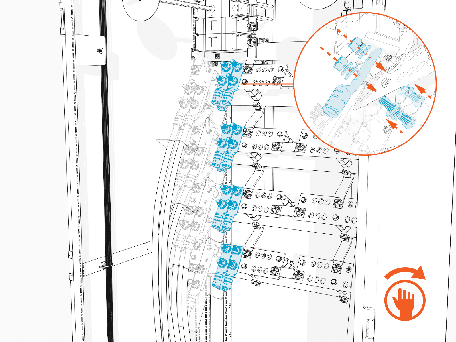
Two wires can be installed with one set of fasteners, as shown above, with one wire on top of the terminal and one wire beneath the terminal.
-
Pull each wire up to reach its corresponding lug, until the wire end reaches the top of the lug barrel. Cut the wire to length.
-
Remove the lugs from the terminals.
Connect High Voltage DC Ouput Wires
In this stage of the installation, the high voltage DC output wires are connected to their terminals. Repeat the steps below for each set of wires scheduled to land on a high voltage DC output terminal. See Wire Landing Locations for location of wire landings.
- See Materials for lug specifications.
- Make sure no wire material is exposed below the lug barrel. If necessary, heat shrink or tape the exposed area to meet local code requirements.
- Make the connections starting at the lowest terminal and work upwards.
-
Hold the wire end parallel to a lug, aligning the tip of the wire to the top of a lug barrel. Mark the length of the barrel on the wire.
-
Strip the wire to the marked length.
-
Crimp the lug onto the wire.
-
Apply dialetric grease to back of the lug.
-
Install the lugs onto high voltage DC output terminal.
Install the lugs using:
-
1/2 x 2-1/4 in bolt
-
1/2 in lock washer
-
1/2 in flat washer
-
1/2 in Belleville washer
-
1/2 in hex nut
Two wires can be installed with one set of fasteners, as shown above, with one wire on top of the terminal and one wire beneath the terminal.
-
-
Torque the fasteners to 61.6 Nm (45 ft-lb).
-
Mark all torqued connections.
-
Repeat for all wire sets landing on the high voltage DC output terminals, working from lowest terminals to highest terminals.
Low Voltage Wires
To pull and connect low voltage wires, perform the steps given below.
Pull Wires
-
Label the 48 V DC and Ethernet wires at both ends.
-
Use a cable puller or fish tape to pull the 48 V DC and Ethernet wires through the conduits. If necessary, use a non-conductive wire pulling lubricant to facilitate the pull.
-
Wipe off any remains of wire pulling lubricant if applied while pulling the wires. Use paper towel.
-
Perform conductor insulator test on the 48 V DC wires. Have the results ready to present upon request.
Connect 48 V DC Wires
-
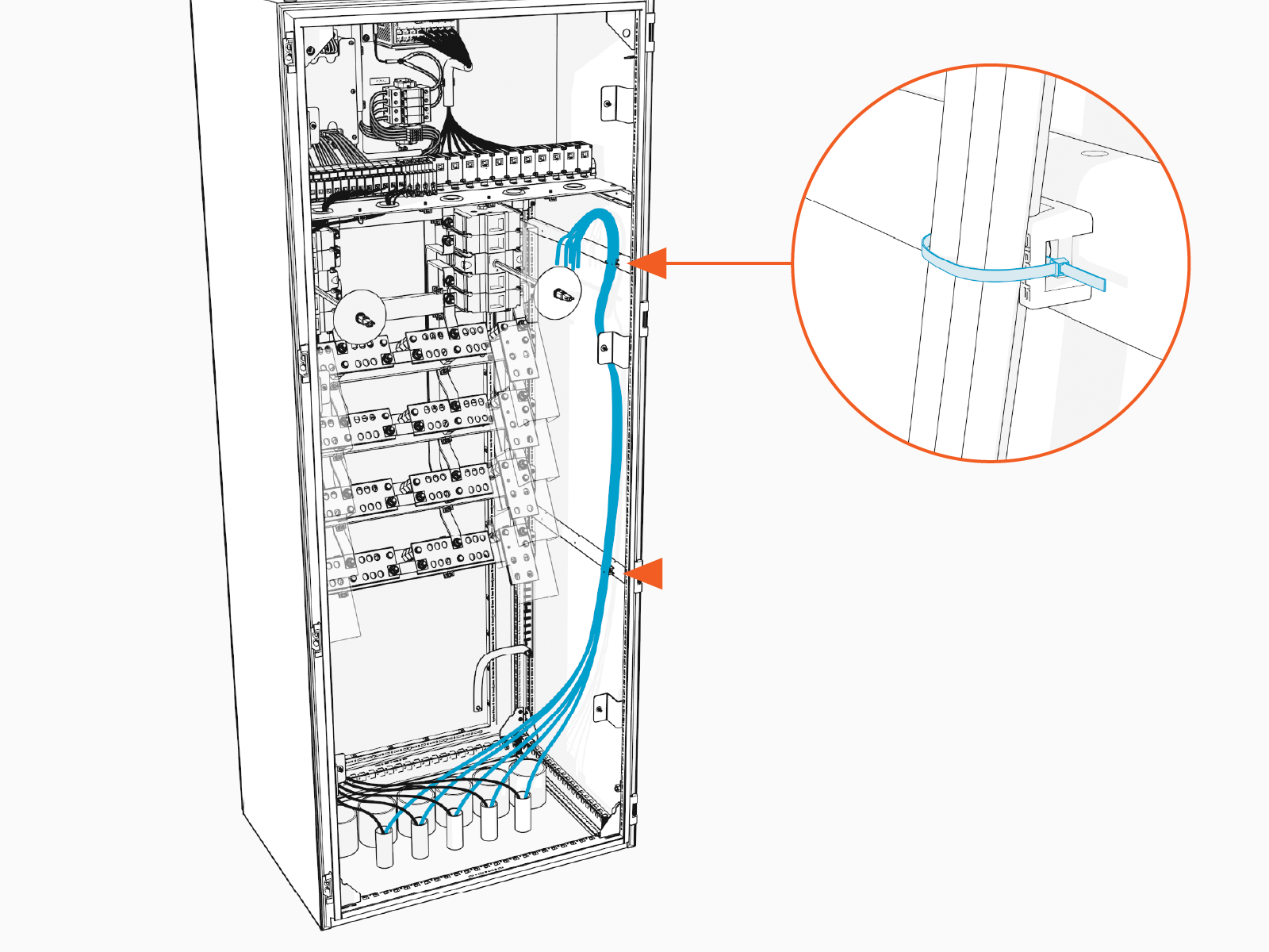
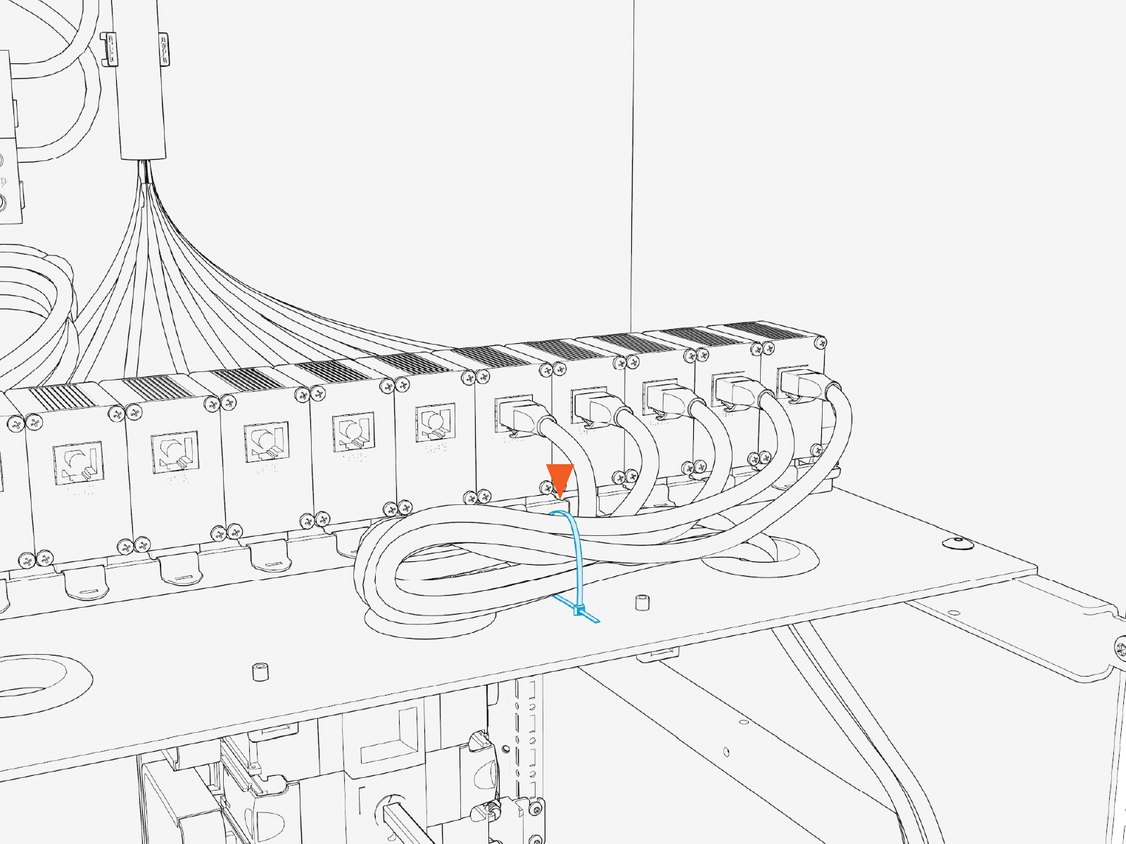
Route the 48 V DC wires up the left side of the high voltage cabinet. Use cable ties to secure the wires to cabinet wall clips.
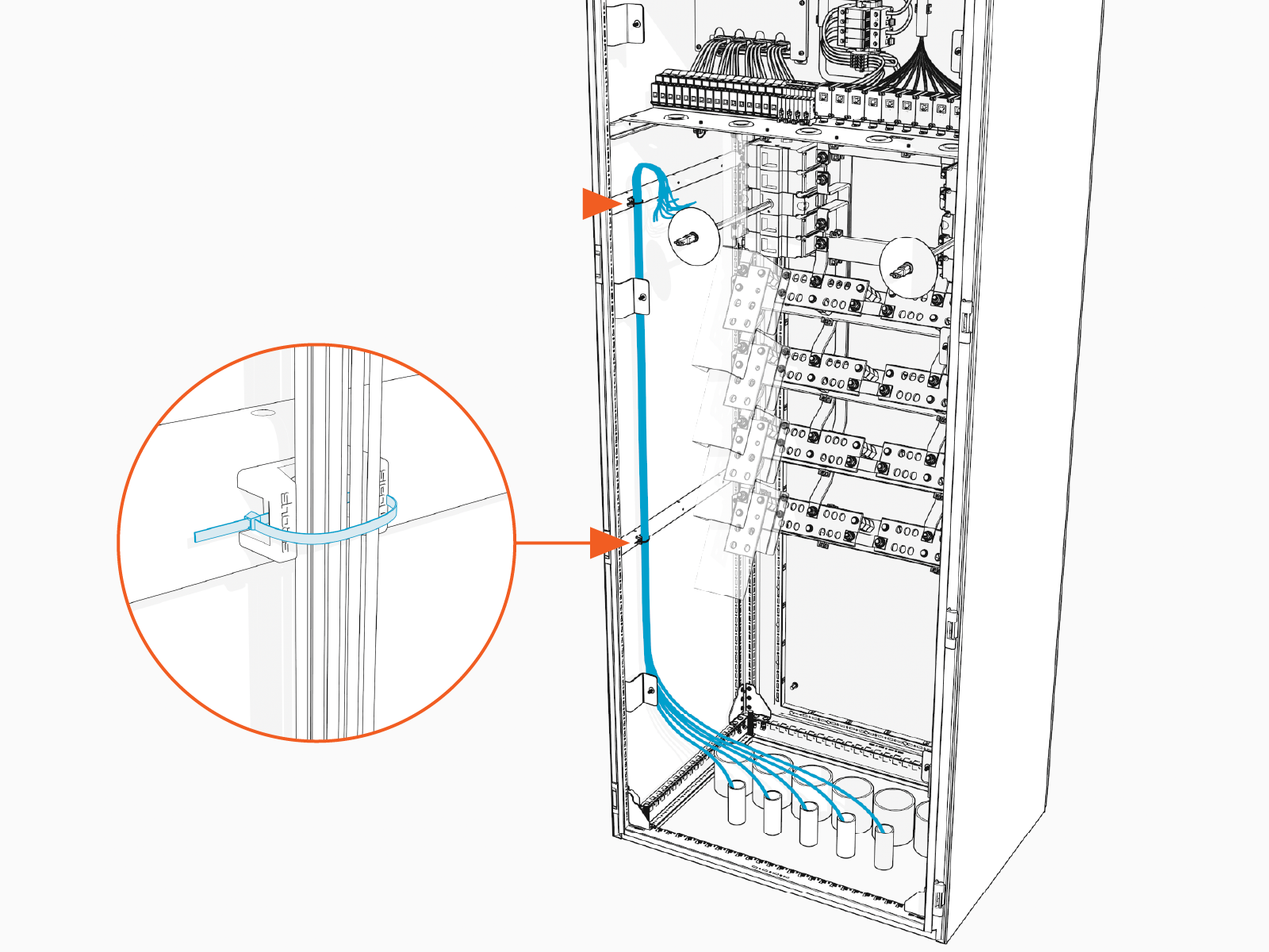
-
Route the wires across the ceiling of the high voltage cabinet and then through a grommet hole to reach the respective 48 V DC terminal block in the low voltage cabinet. See Wire Landing Locations. Use cable ties to secure the wires to the ceiling of the high voltage cabinet.
Ensure the wires route through a grommet hole to prevent them from being pinched against the dead front.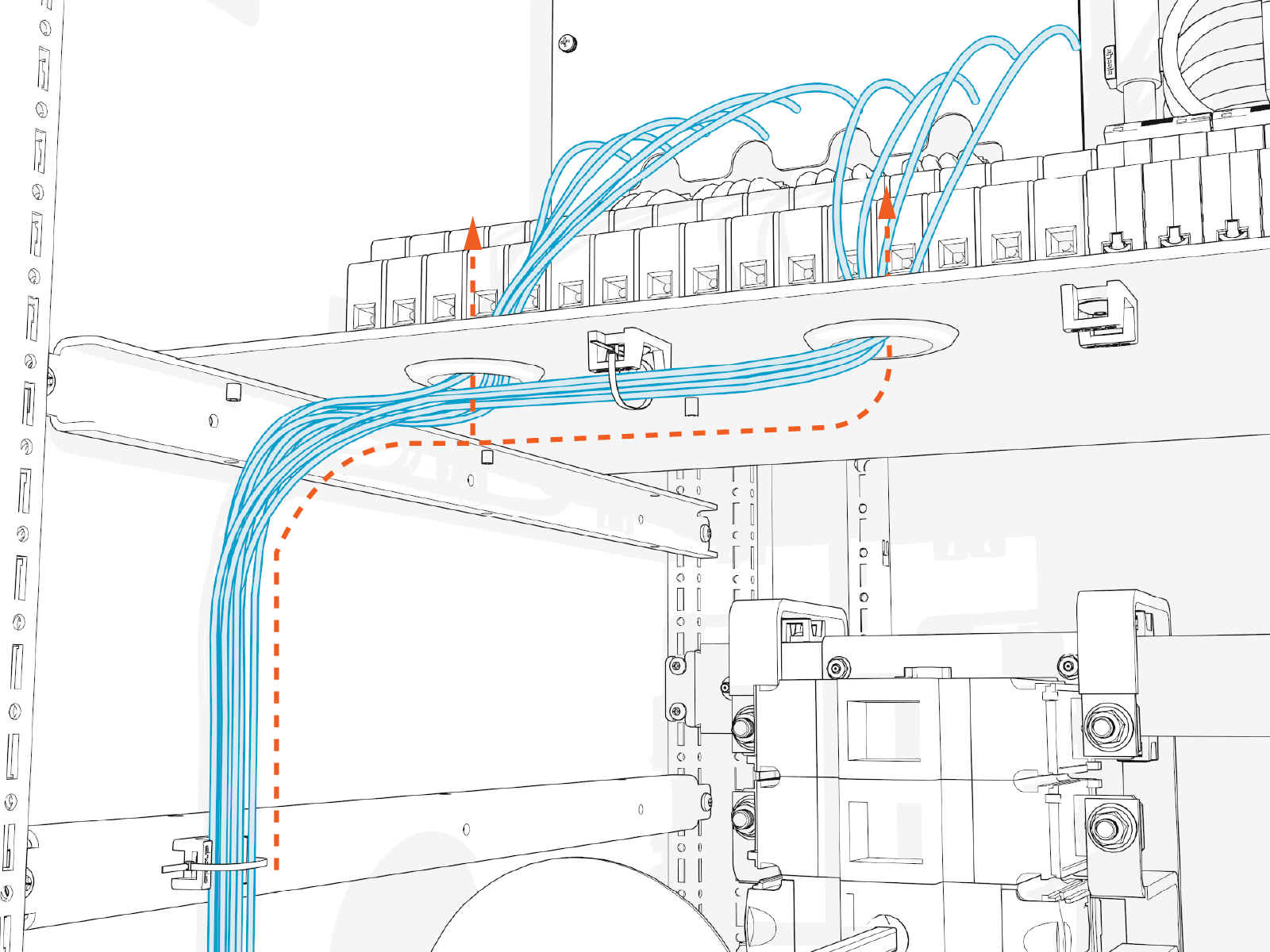
-
Loosen the set screws on the 48 V DC input circuit breaker and output fuse holders.
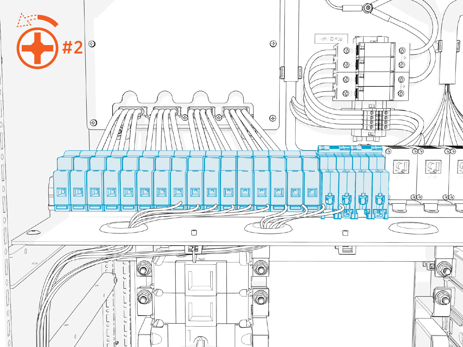
-
Cut the wires to length. Strip the wire ends 14 mm (0.6 in).

-
Insert each wire into its corresponding circuit breaker (input wire) or fuse holder (output wire).
Insert positive wires (red) into the positive (+) terminals.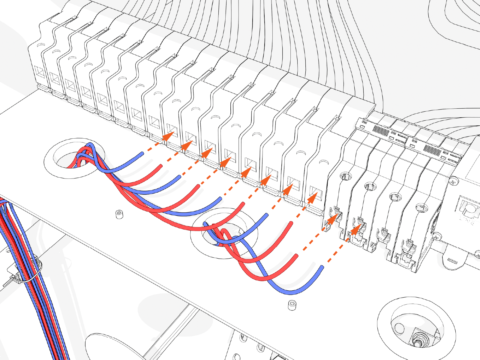
-
Tighten fuse holder set screws to 1.7 Nm (15 in-lb). Tighten circuit breaker set screws to 2.8 Nm (25 in-lb). Push-pull to test each connection is secure.
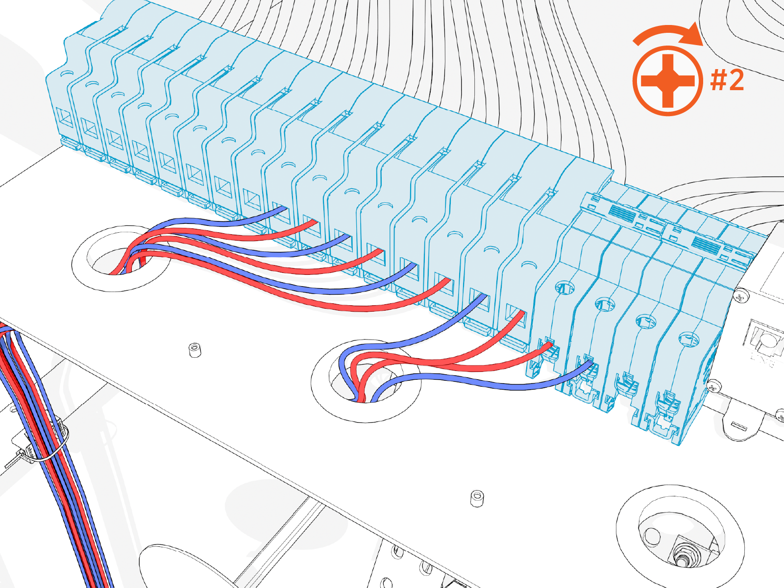
-
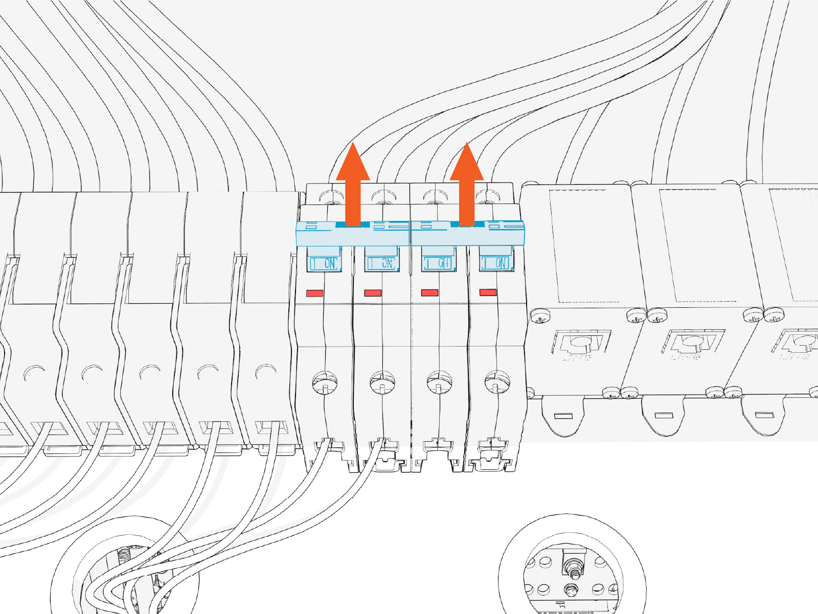
Ensure the relevant circuit breaker switches are in the ON position.
Connect Ethernet Cables
-
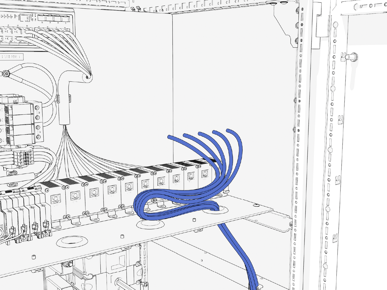
Route the Ethernet cables up the right side of the high voltage cabinet. Use cable ties to secure the wires to cabinet wall clips.
-
Route the Ethernet cables across the ceiling of the high voltage cabinet and then through a grommet hole to reach their respective Ethernet ports in the low voltage cabinet. See Wire Landing Locations for location of wire landings. Use cable ties to secure the cables to the ceiling of the high voltage cabinet.
Ensure the cables route through a grommet hole to prevent them from being pinched against the deadfront.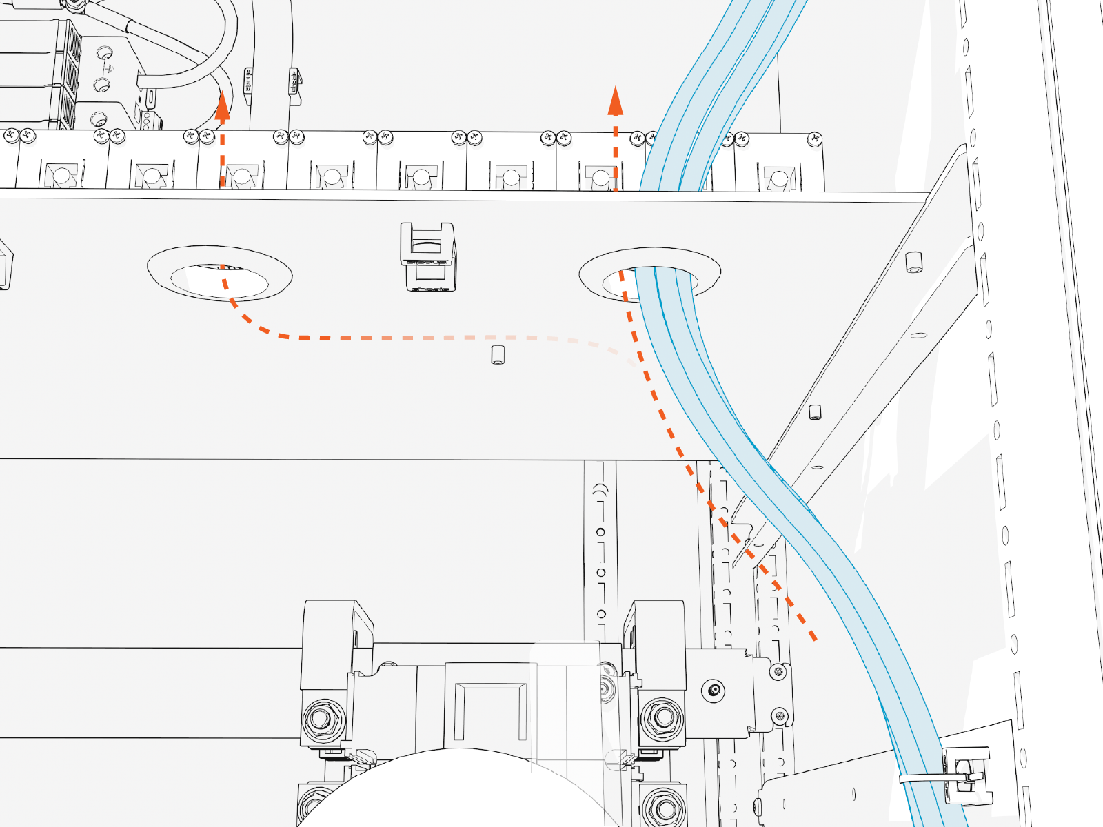
-
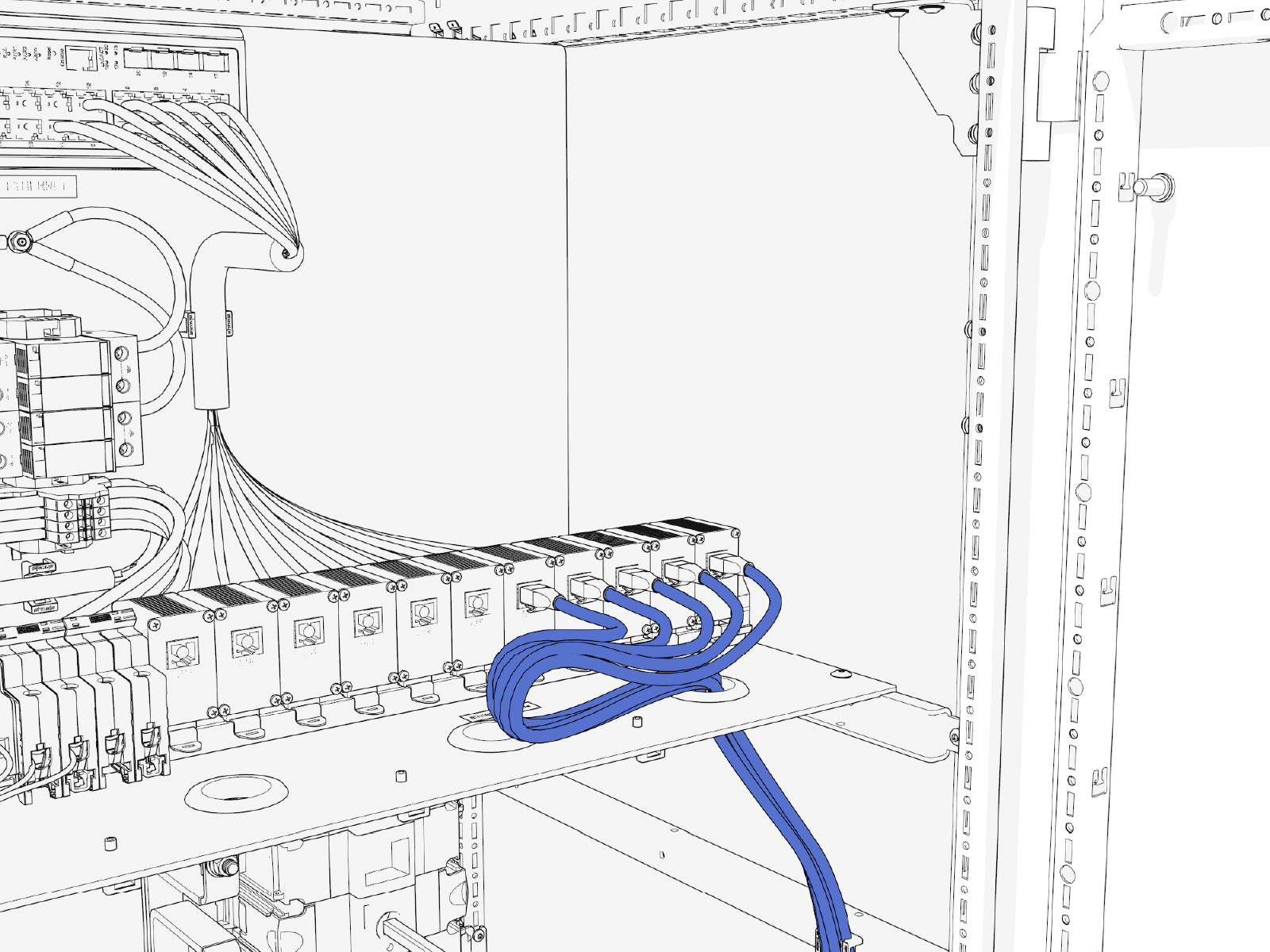
Trim loose end of the Ethernet cable to length. Allow for a service loop that lies horizontally across the bottom shelf of the cabinet.
-
Field crimp a shielded RJ45 connector onto the end of each Ethernet cable. Use a straight-through T568B pattern.
For Ethernet cables connecting from the Power Hub to Power Link 1000s, ground the shield wire at the Power Hub. For Ethernet cables connecting from the Power Hub to Power Blocks, do not connect the shield wire at the Power Hub. The shield wire must ground at the Power Block.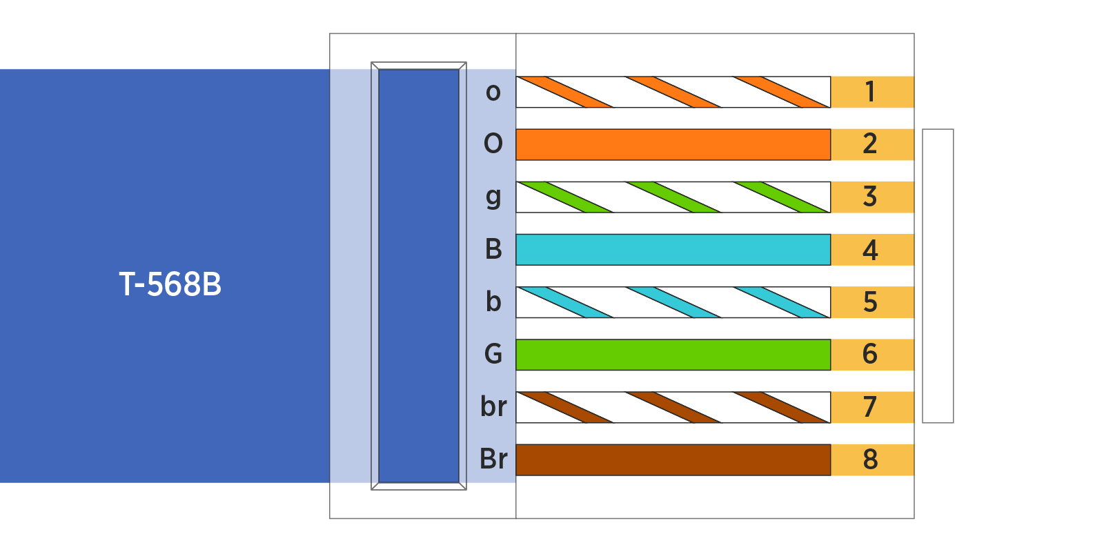
-
Test each Ethernet cable for functionality. Use an Ethernet tester.
-
Connect each Ethernet cable to an Ethernet port. All ports are interchangeable. There should be an audible click upon insertion. Push-pull to test the connection.
-
Use cable ties to dress the Ethernet cables.
Finalize the Installation
To finalize the installation, complete the following steps:
-
Vacuum all wire ends and metal shavings from the cabinet.
-
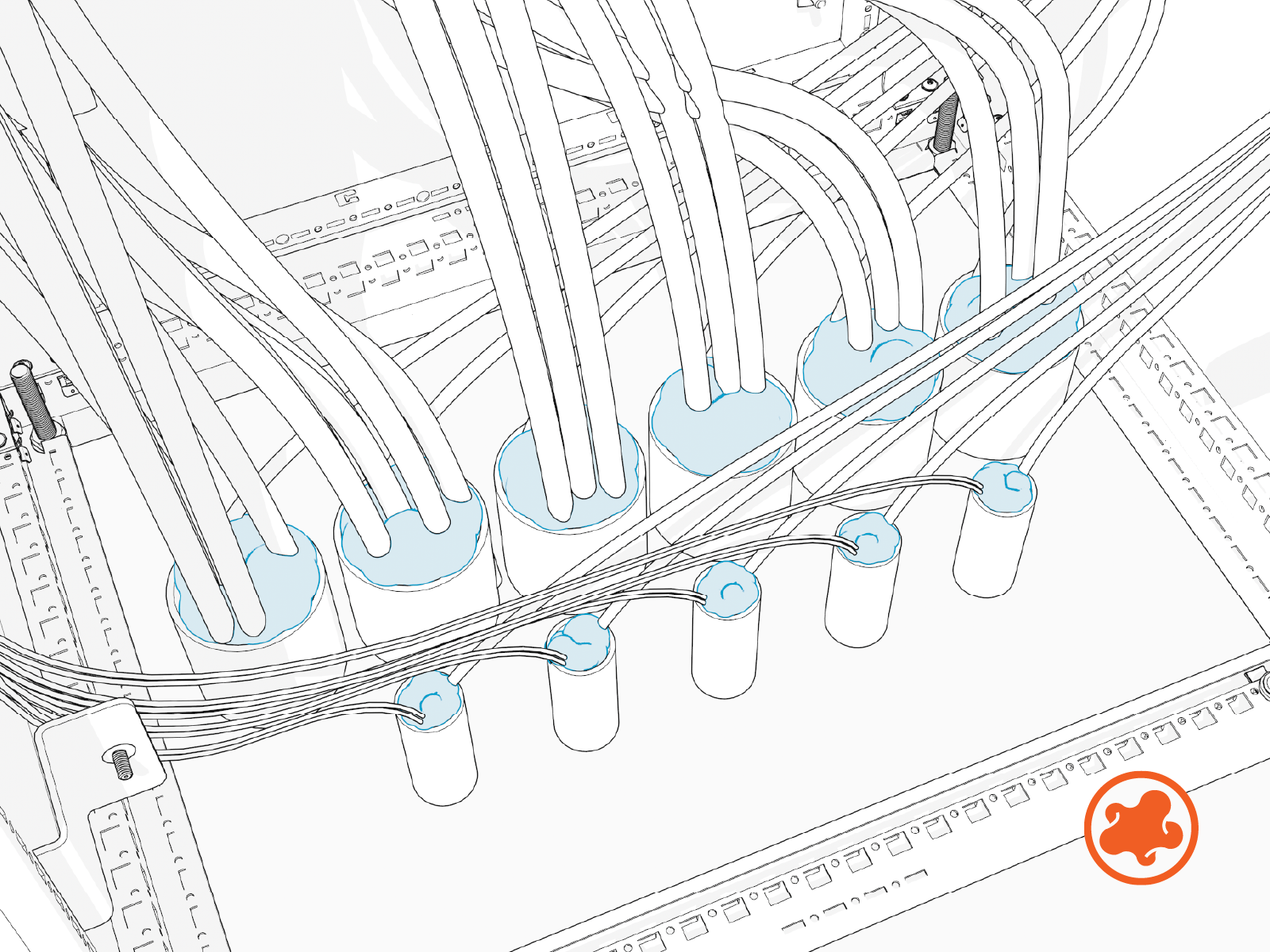
Use duct seal compound to seal inside conduit openings.
-
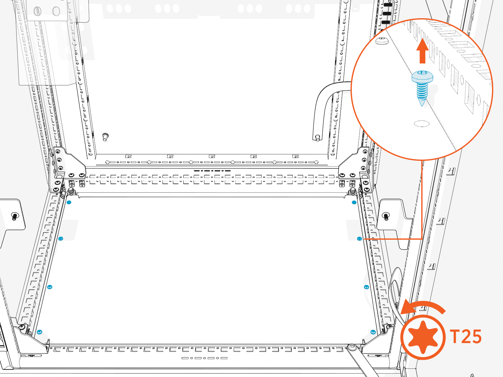
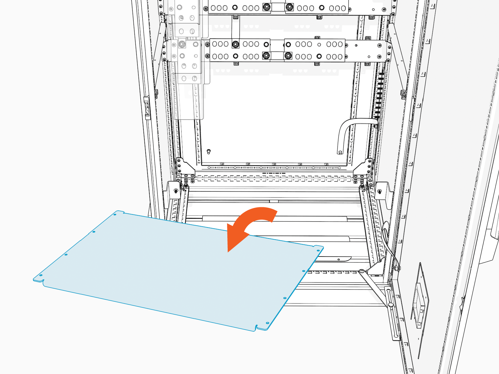
Reinstall the low voltage cabinet dead front. Tighten captive screws (x2) on the dead front. Torque to 5.6 Nm (50 in-lb).
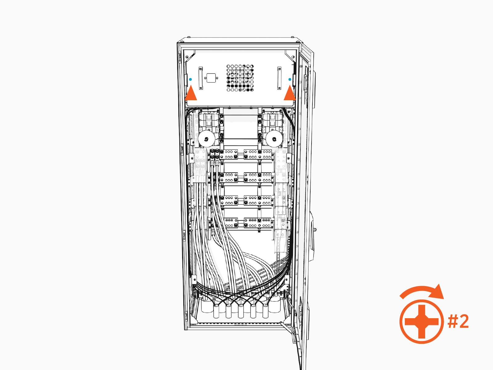
-
Reinstall the high voltage cabinet dead front. Be sure the disconnect switch shaft inserts into the disconnect handle on the dead front. Tighten the captive screws (x4) on the dead front. Torque to 5.6 Nm (50 in-lb).

-
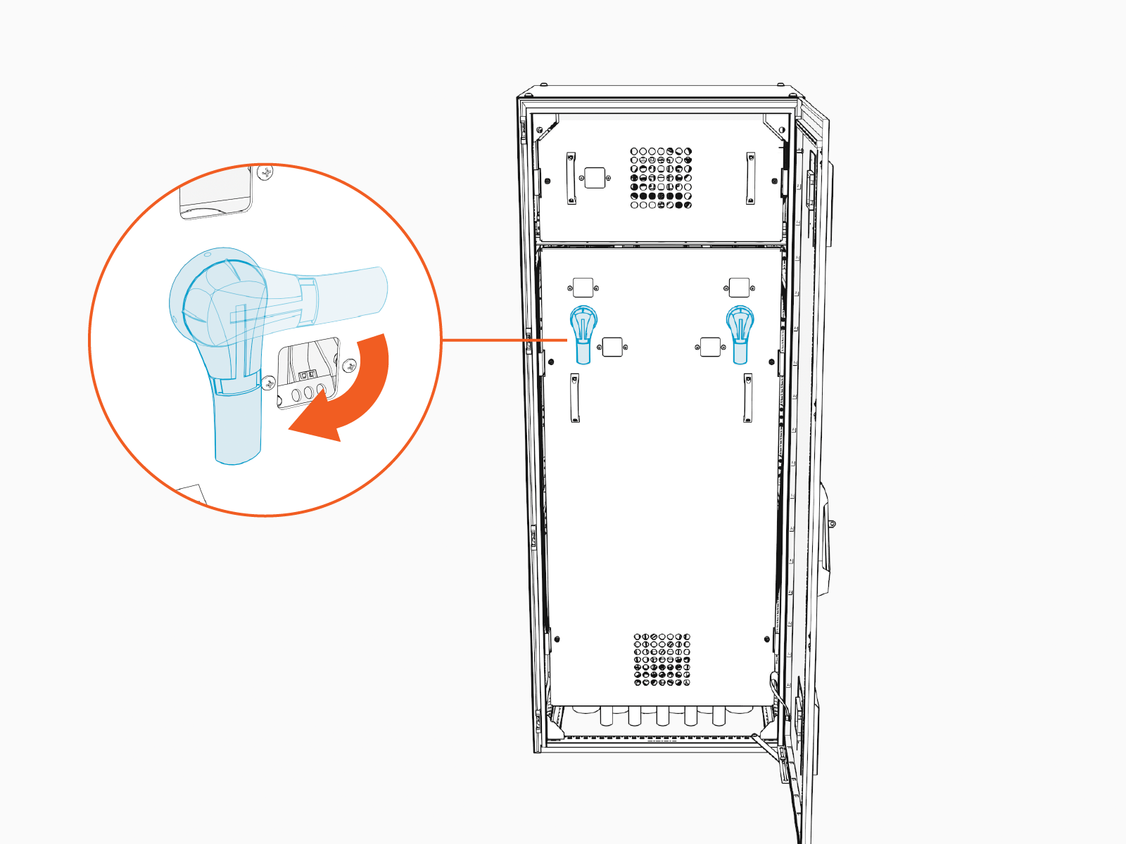
Turn each disconnect switch handle to the ON position. Align the fin on the handle with the ON mark.
-
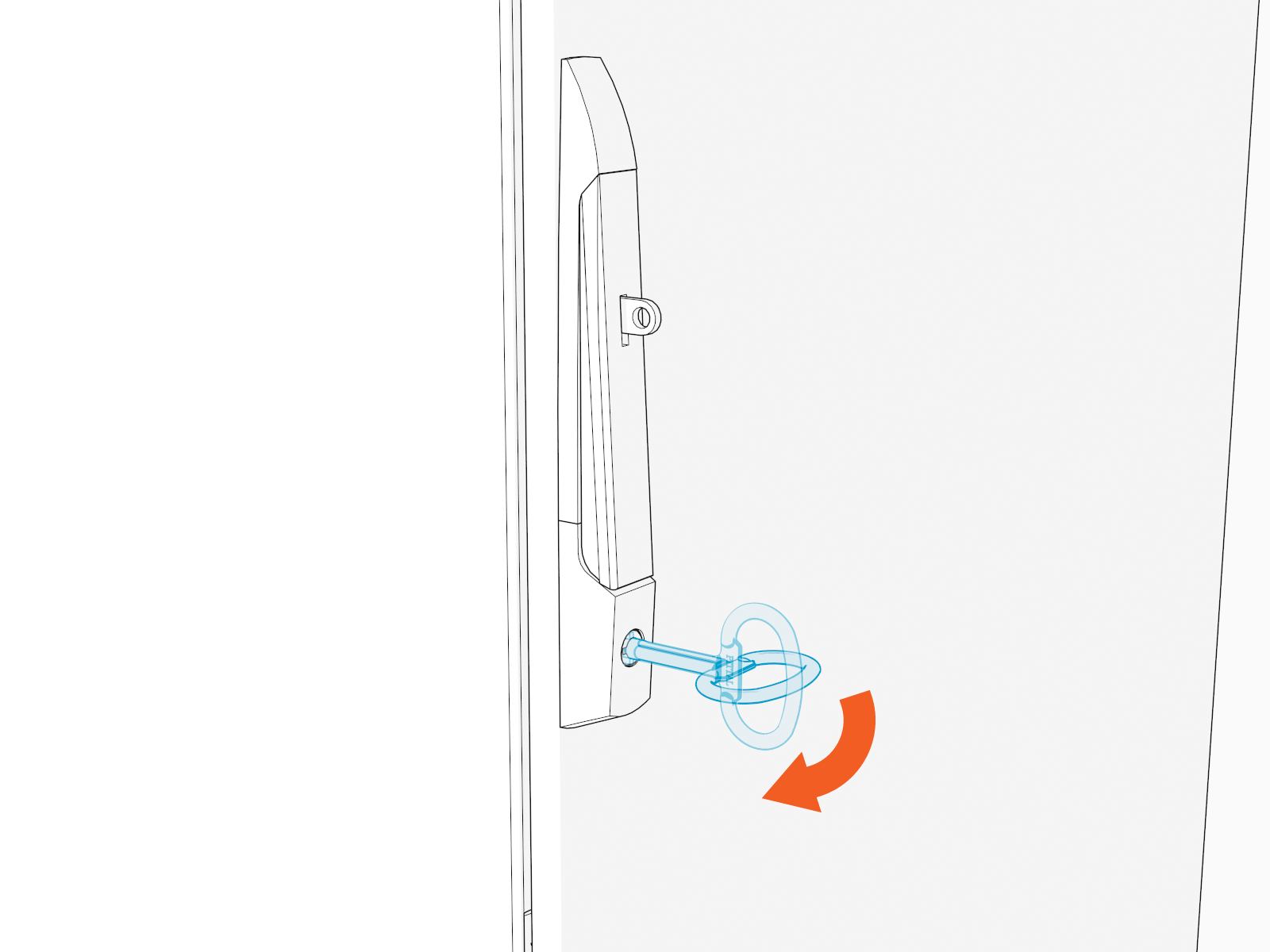
Close and lock the door. Retain the key for future servicing of the Power Hub.
-
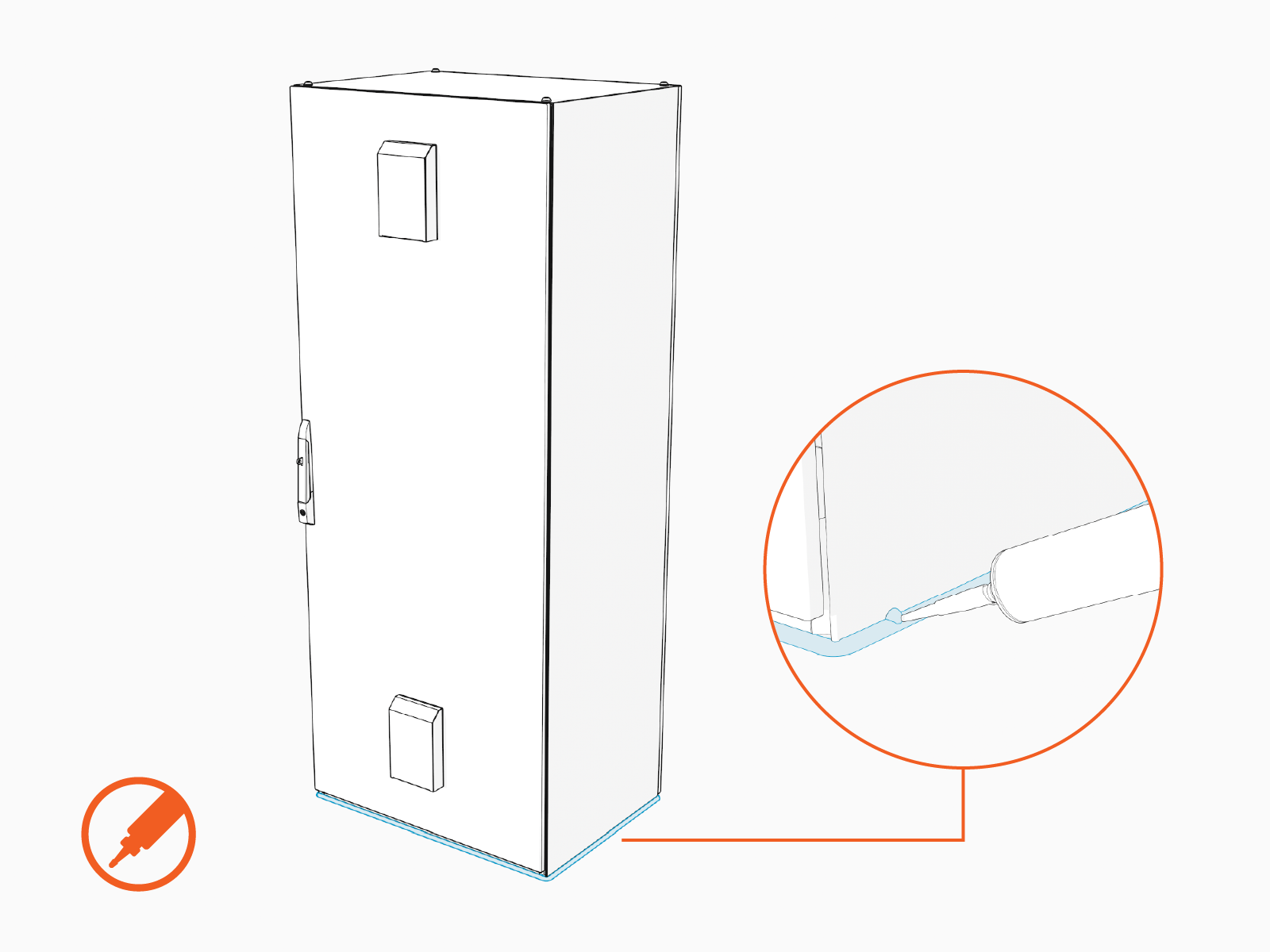
Use a weatherproof sealant to fully seal the Power Hub base to the concrete surface.