Appendix: Install Second Input Kit
The Power Hub ships equipped for high voltage DC inputs from one Power Block, denoted Power Block Left. This default configuration includes hardware for landing high voltage DC cables from Power Block Left, and a disconnect switch for high voltage DC power shutoff from Power Block Left.
The Power Hub can be configured to accept high voltage inputs from a second Power Block, denoted Power Block Right, by installing a Second Input Kit. The Second Input Kit includes hardware for landing high voltage DC input cables from Power Block Right, as well as a second disconnect switch for power shutoff from Power Block Right. Adding a second Power Block to a Power Hub doubles the potential power available to share across connected Power Link 1000s.
The Second Input Kit must be ordered separately, and is field installed into the Power Hub. Installation of the Second Input Kit can be performed solely from the front side of the cabinet; however it is more easily installed when there is both front and rear acess to the cabinet. In cases where the rear clearance of an installed Power Hub is less than 812.8 mm (32 in), it is easiest to install the Second Input Kit prior to mounting the Power Hub into its final location. For example, it may be installed in the field while the Power Hub is still attached to its shipping pallet. For the case in which an installed Power Hub may be connected to a second Power Block at a future time, consider pre-installing a Second Input Kit prior to initial cabinet mount.
Follow instructions in this appendix to unpack and install the Second Input Kit.
These instructions assume the Power Hub cabinet is already opened. If the cabinet is not yet opened, see Unpack the Power Hub
Required Tools and Materials
|
|
Hard hat |
|
Cut-resistant gloves |
|
|
Safety glasses |
|
Lock out/tag out equipment |
|
|
Multimeter with CAT III 1000 V ratings, such as Fluke 87V or similar |
|
Box cutter |
|
|
Torque wrench driver |
|
Torque screwdriver |
|
|
Hex socket set (10 mm, 7/16 in, 9/16 in, including deep socket) |
|
Hex wrench set (2.5 mm, 3/16 in, 9/16 in, and adjustable) |
|
|
T30 Security screwdriver |
|
|
Tightening Torque
|
Component |
Fastener (Qty) |
Tool |
Torque |
|
Cabinet rear panel |
T30 Security screw (x8 ) |
T30 security screwdriver |
5.1 Nm (45 in-lb) |
|
Rear panel ground strap |
3/8 in hex nut (x1) |
9/16 in socket wrench |
8.5 Nm (75 in-lb) |
|
Disconnect switch body |
#10 hex nut (x4) |
10 mm socket wrench |
3.4 Nm (30 in-lb) |
|
Flex jumpers at disconnect switch |
3/8 in hex nut (x8) |
9/16 in socket wrench |
35 Nm (26 ft-lb) |
|
Flex jumpers at bus bar |
3/8 in hex nut (x8) |
9/16 in socket wrench |
42.4 Nm (31 ft-lb) |
|
High voltage DC bus assembly |
1/4 in hex bolt (x8) |
7/16 in socket wrench |
10.2 Nm (90 in-lb) |
|
High voltage DC bus safety cover |
Captive screws (x16) |
3/16 in hex wrench |
2.8 Nm (25 in-lb) |
|
Disconnect switch safety cover |
Captive screws (x2) |
3/16 in hex wrench |
Unpack the Second Input Kit
The Second Input Kit ships in its own box, separate from the Power Hub. Unpack the box and check to make sure the following parts are present:
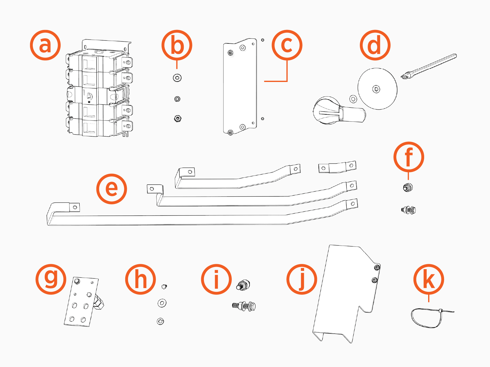
-
Disconnect switch
-
Disconnect switch fasteners (x4)
-
#10 flat washer
-
#10 split lock washer
-
#10 hex nut
-
-
Disconnect switch safety cover
-
Disconnect switch handle kit (x1)
-
Disconnect handle
-
400 mm shaft
-
0.412 inch o-ring (x2)
-
Shaft warning tag
-
-
Set of flex jumpers (2 sets of four)
-
Flex jumper fasteners (x16)
-
3/8 x 1-1/4 inch hex head bolt
-
3/8 inch split washer
-
5/16 inch flat washer (x2)
-
3/8 inch belleville washer
-
3/8 inch hex nut
-
-
High voltage DC bus assemblies (x4)
-
High voltage DC bus assembly fasteners (x8)
-
1/4 x 5/8 inch hex head bolt
-
1/4 inch split lock washer
-
1/4 inch small flat washer
-
-
High voltage lug fasteners (x16)
-
1/2 x 2-1/4 inch hex bolt
-
1/2 inch lock washer
-
1/2 inch flat washer (x2)
-
1/2 inch belleville washer
-
1/2 inch hex nut
-
-
High voltage bus safety cover (x4)
-
Zip ties (x20)
Disconnect Power
- Before any procedure, disconnect the power.
- Follow local code and site lockout/tagout procedure to de-energize the station.
- Wait for energy to dissipate (approximately five minutes).
- Keep power off until all covers and panels are reinstalled and the work is complete.
-
Disconnect power at the Power Block that feeds the Power Hub.
Follow standard practice and local code to de-energize the applicable circuit and lock out/tag out the disconnect before proceeding.

-
Use a multimeter to test that power is off.
Mount the Disconnect Switch
To mount the disconnect switch, complete the following steps:
-
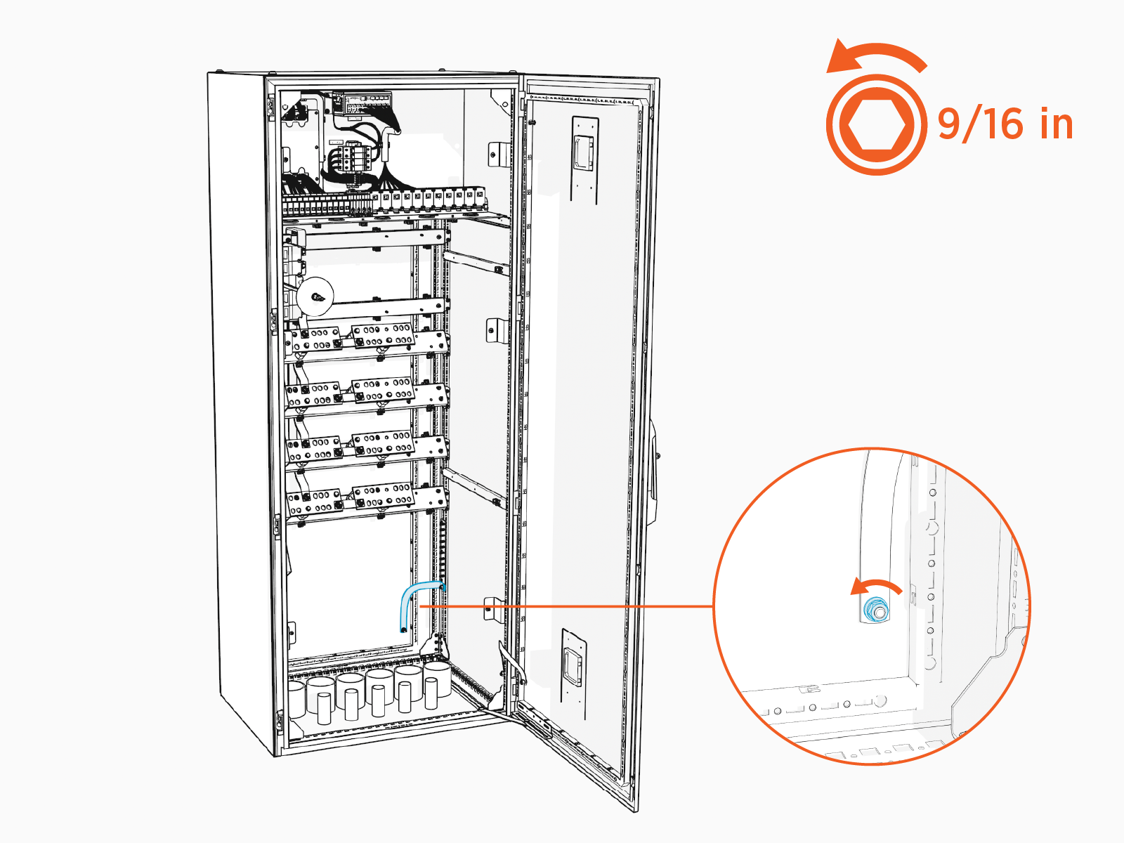
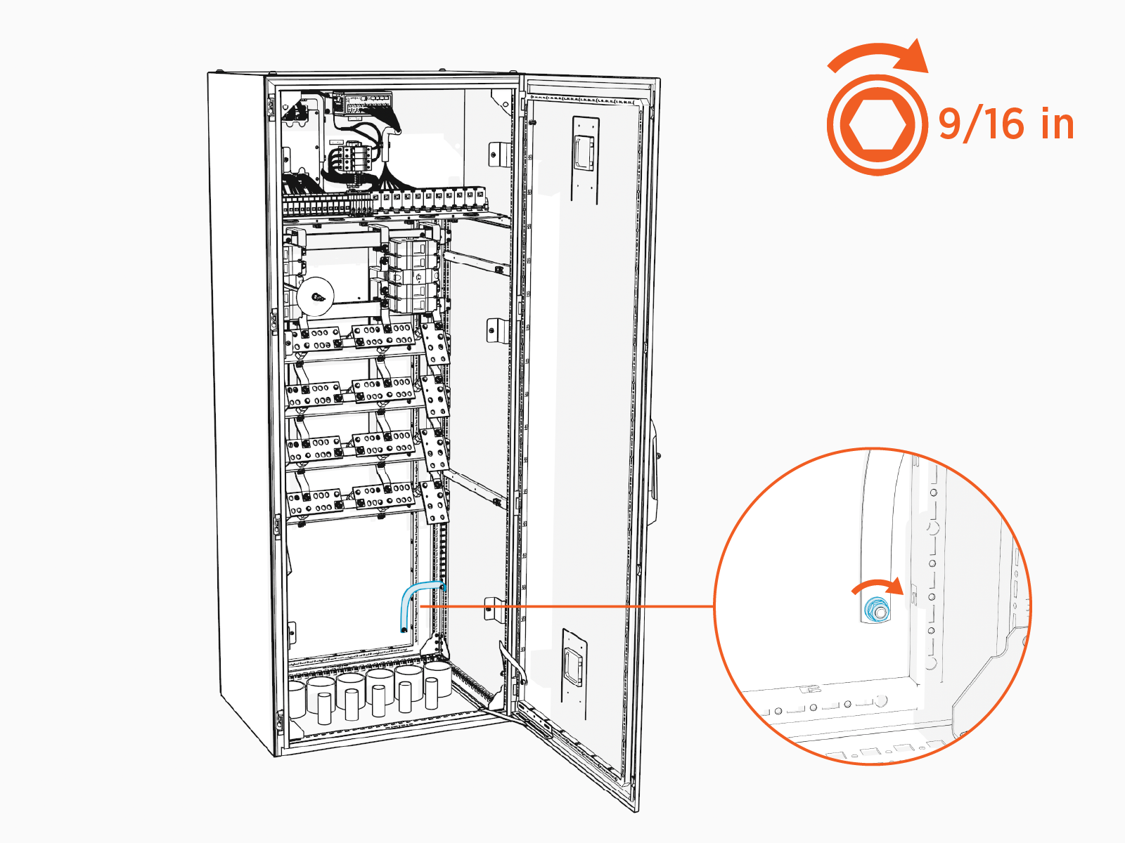
If there is sufficient clearance behind the Power Hub, remove the rear panel of the cabinet. Skip this step if there is not enough clearance to remove the panel. Panel removal makes the installation process easier to carry out, but is not required.
-
Remove the nut and washers securing the rear panel. Set aside the fasteners for later reinstall.
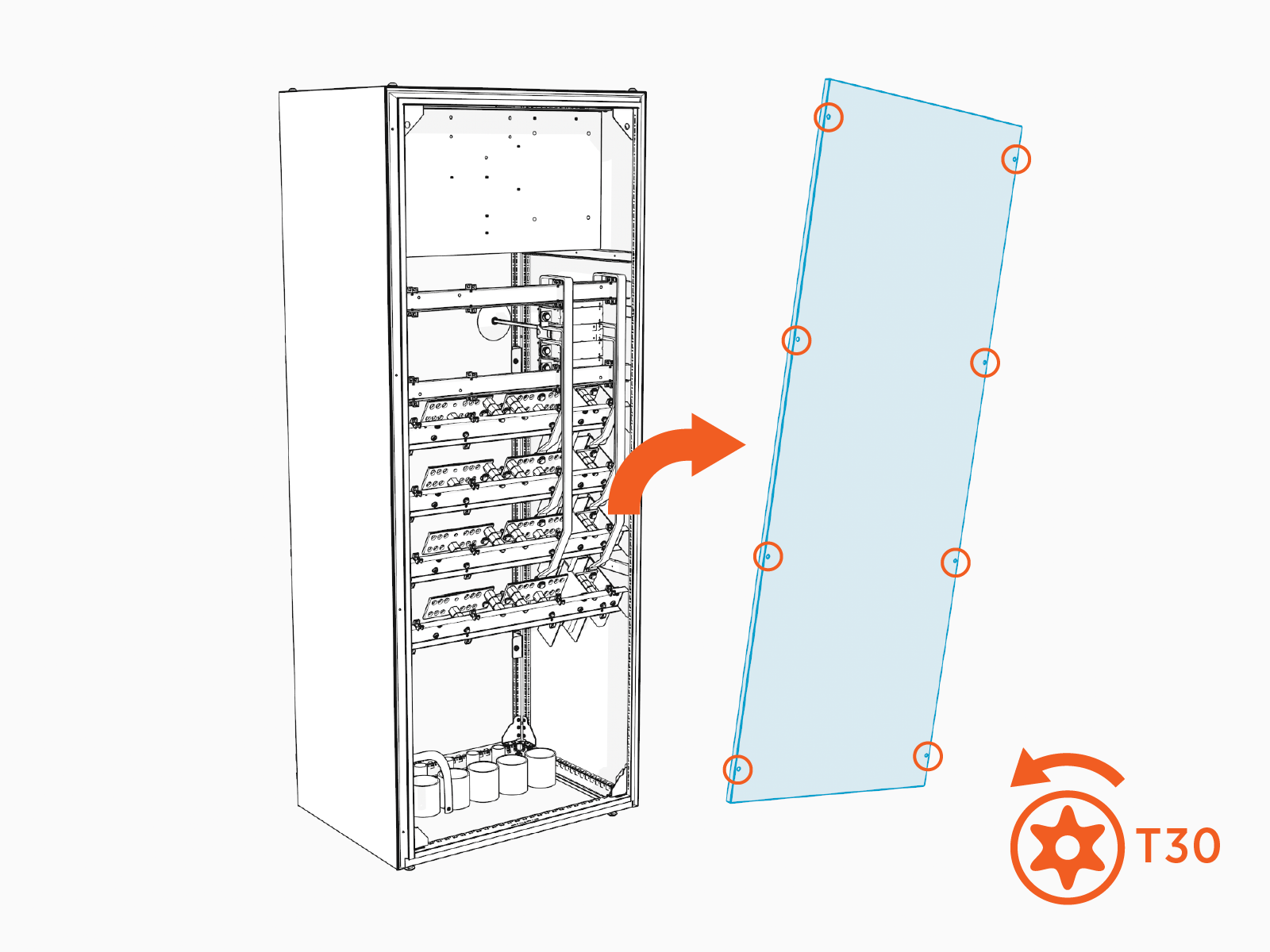
-
Remove the T30 Security screws (x8) on the rear panel. Remove the rear panel. Set aside fasteners and panel for later reinstall.
-
-
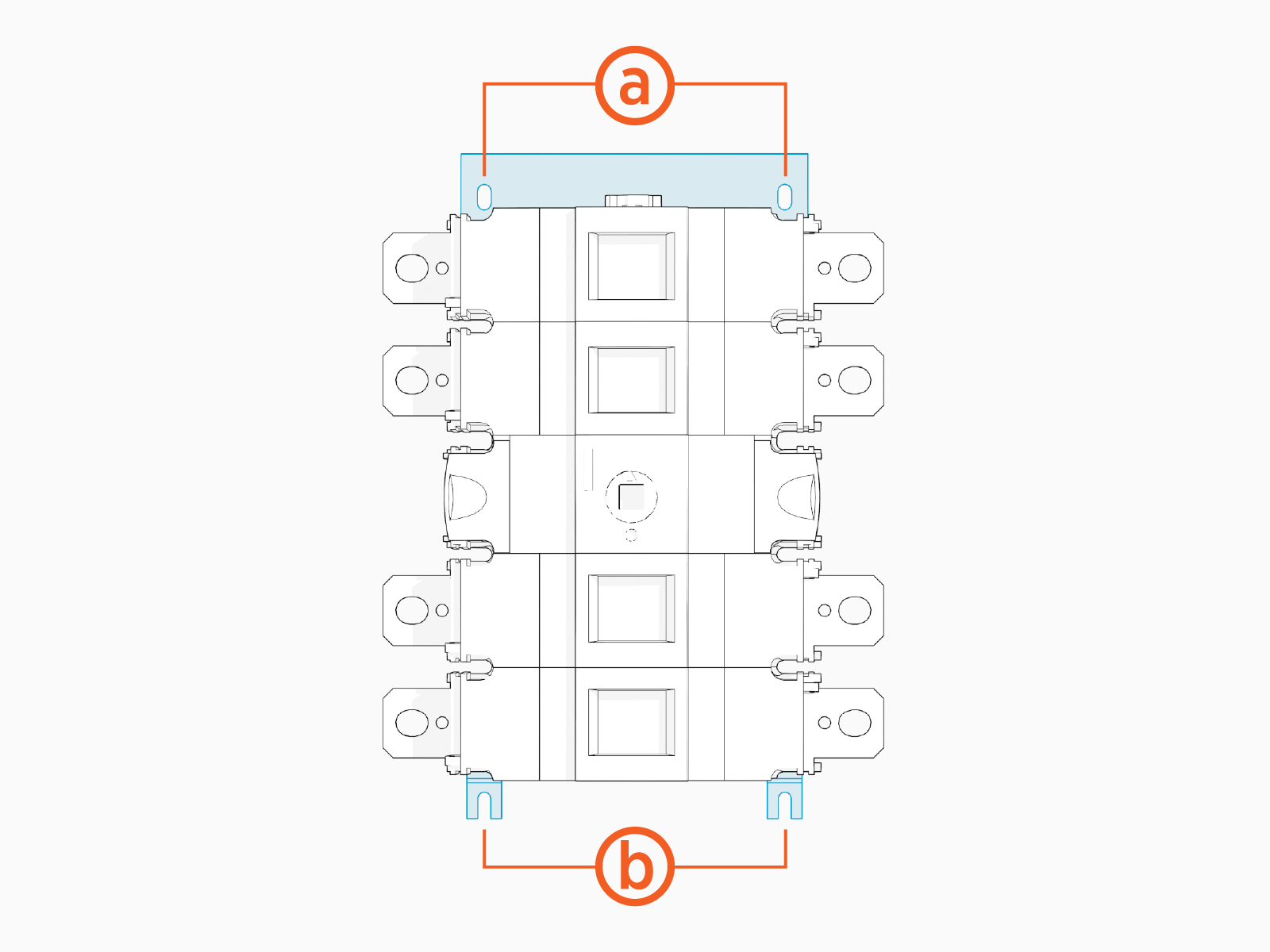
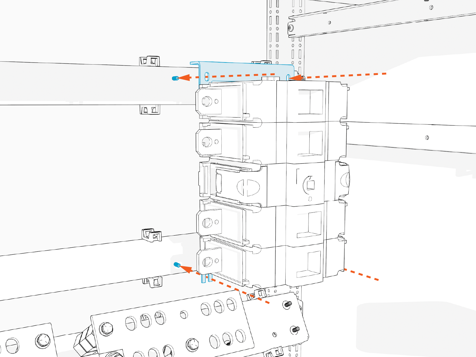
Identify the following parts on the disconnect switch:
-
A top mounting bracket with two mounting holes
-
Two bottom mounting feet
-
-
Inside the Power Hub cabinet locate two studs on the right side of the upper-most horizontal rail. Locate an additional two studs on horizontal rail just below.
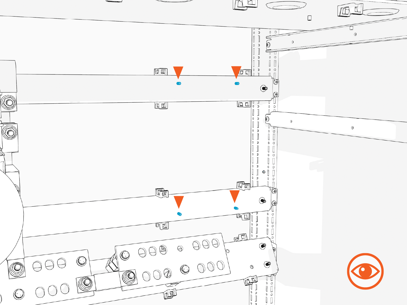
-
Mount the disconnect switch over the studs. Align the top mount holes over the upper studs. Seat the bottom mounting feet over the lower studs. The top mounting bracket should seat on the upper rail.
-
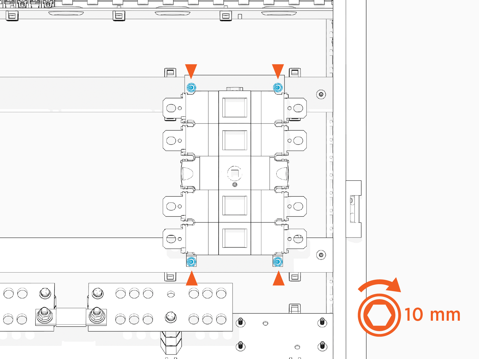
Install #10 fasteners (x4) to secure the top mounting bracket and bottom mounting feet. Hand tighten.
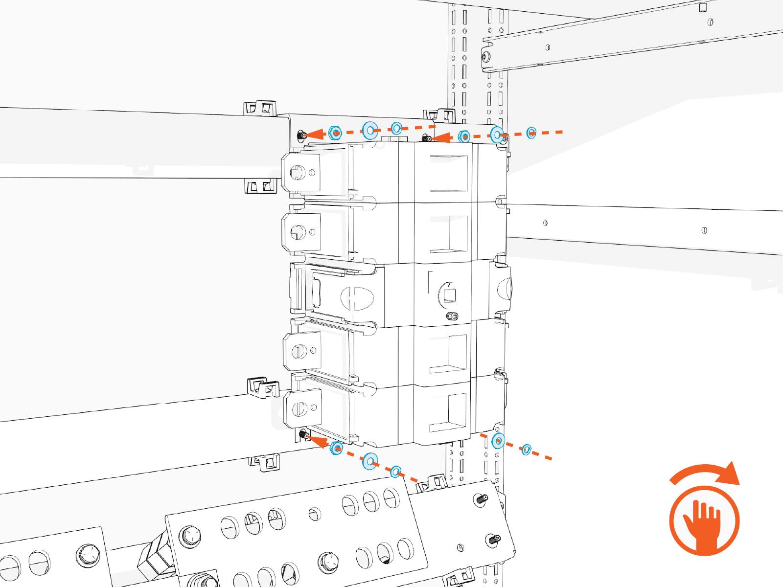
-
Torque the fasteners (x4) to 3.4 Nm (30 in-lb).
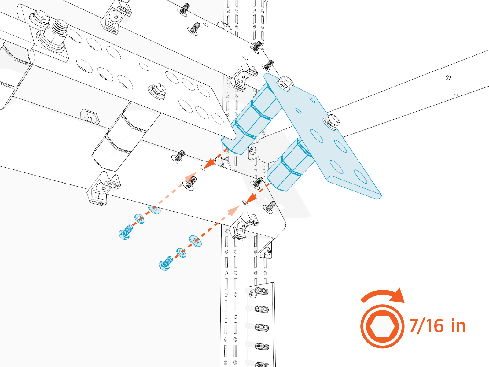
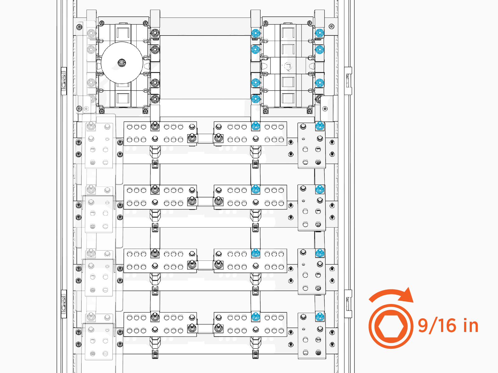
Install High Voltage Input Bus Bars
To install high voltage input bus bars, complete the following steps:
-
Inside the Power Hub cabinet locate four horizontal rails that host the high voltage input and output buses. On the right side of each rail, find two screw holes in a diagonal orientation.
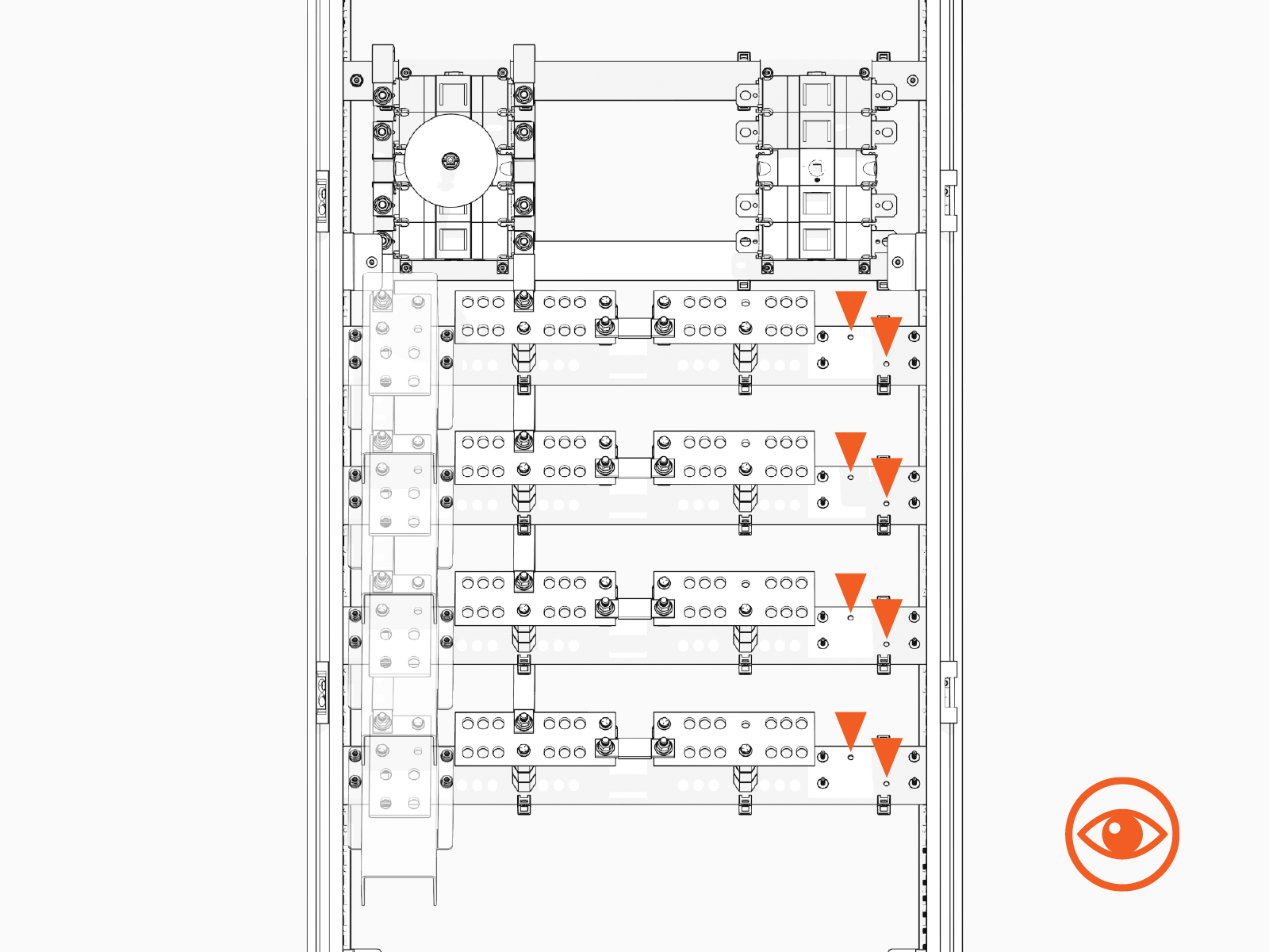
-
Working from the lowest rail to the highest, mount a high voltage DC bus assembly onto each rail. Secure the bus assembly at each screw hole with 1/4 in fasteners. Torque bolts to 10.2 Nm (90 in-lb).
Install Flex Jumpers
To install flex jumpers, complete the following steps:
-
Study the set of jumpers connecting the left disconnect switch to the left-side high voltage output buses.
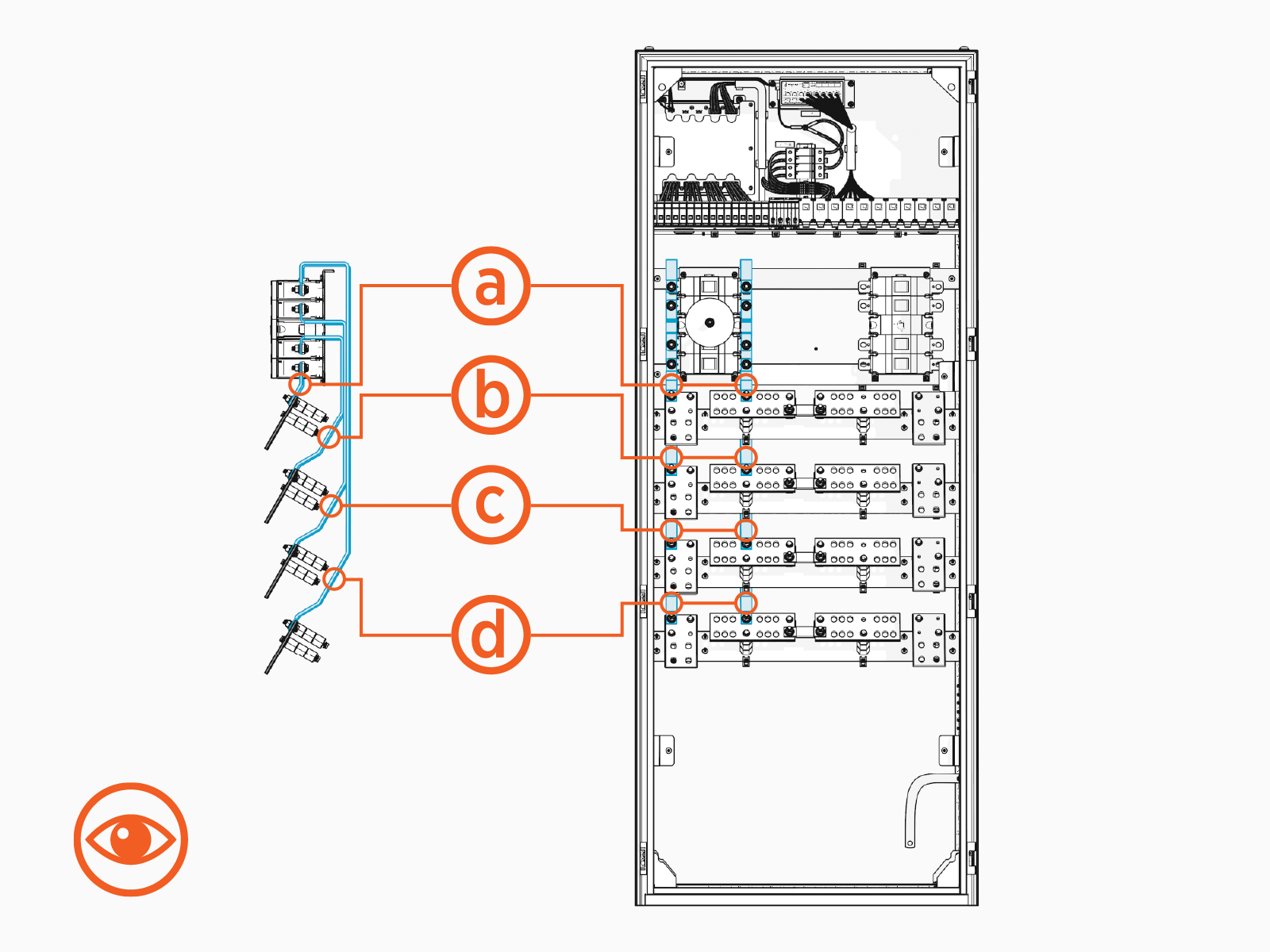
-
Working from shortest to longest jumper, install a duplicate set of jumpers at the right disconnect switch. Secure the jumpers at each end with the fasteners shown below:
-
3/8 in hex nut
-
3/8 in Belleville washer
-
5/16 in large flat washer
-
3/8 in split lock washer
-
3/8 x 1-1/4 in hex head bolt
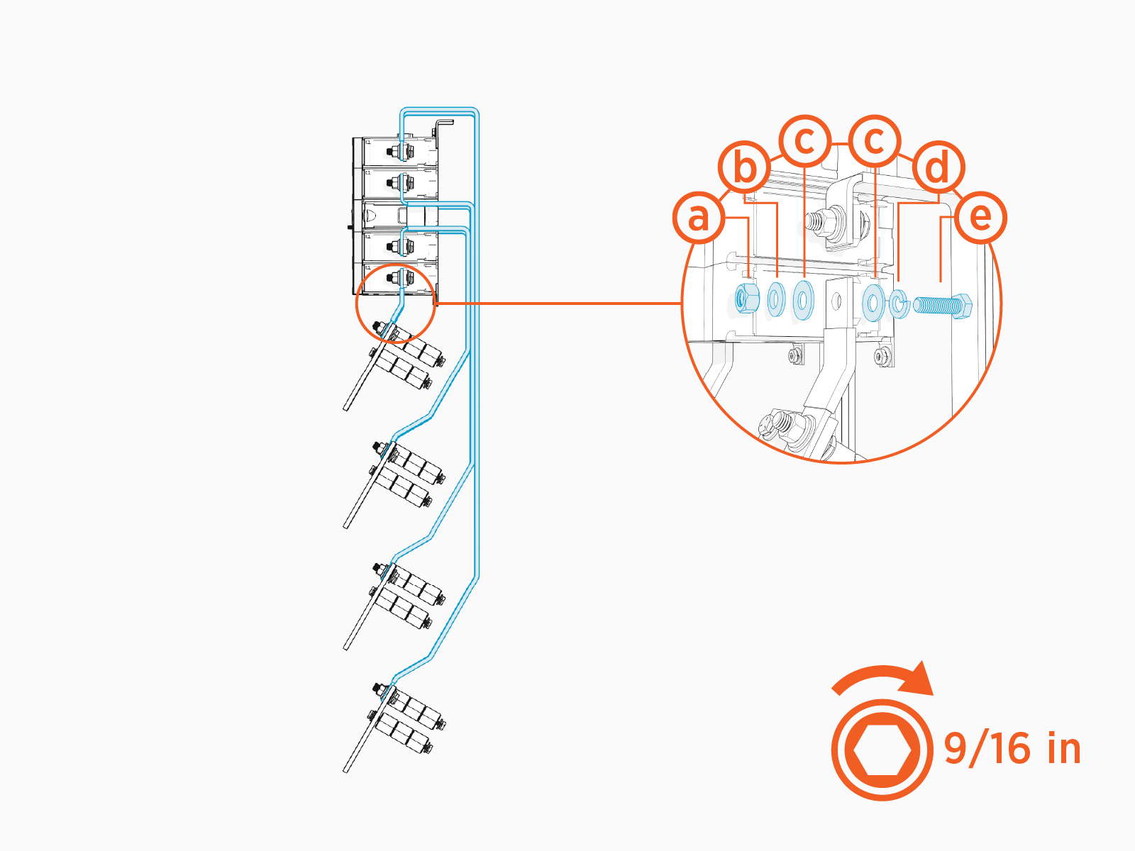
-
-
Torque fasteners (x8) at the disconnect switch to 35 Nm (26 ft-lb). Torque fasteners (x8) at the high voltage DC buses to 42.4 Nm (31 ft-lb).
-
Use zip ties (20) to secure the flex jumpers at the following locations:
-
Secure flex jumpers to clip with zip tie
-
Secure jumpers together with zip tie
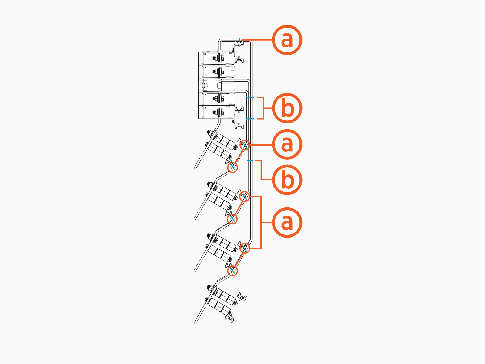
-
-
Trim the ends of the zip ties.
-
If applicable, reinstall the Power Hub cabinet rear panel.
-
Fasten the cabinet rear panel with T30 Security screws (x8). Torque to 5.1 Nm (45 in-lb).
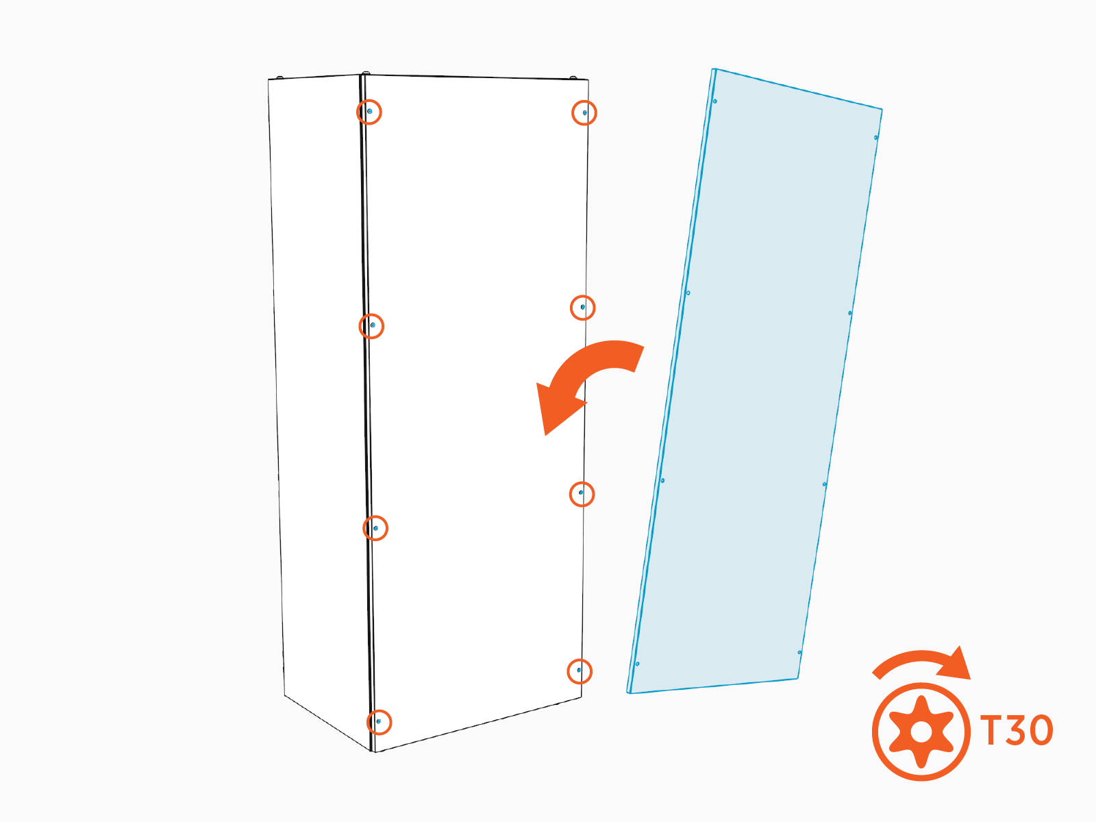
-
Reconnect the ground strap to the rear panel. Torque to 8.5 Nm (75 in-lb).
-
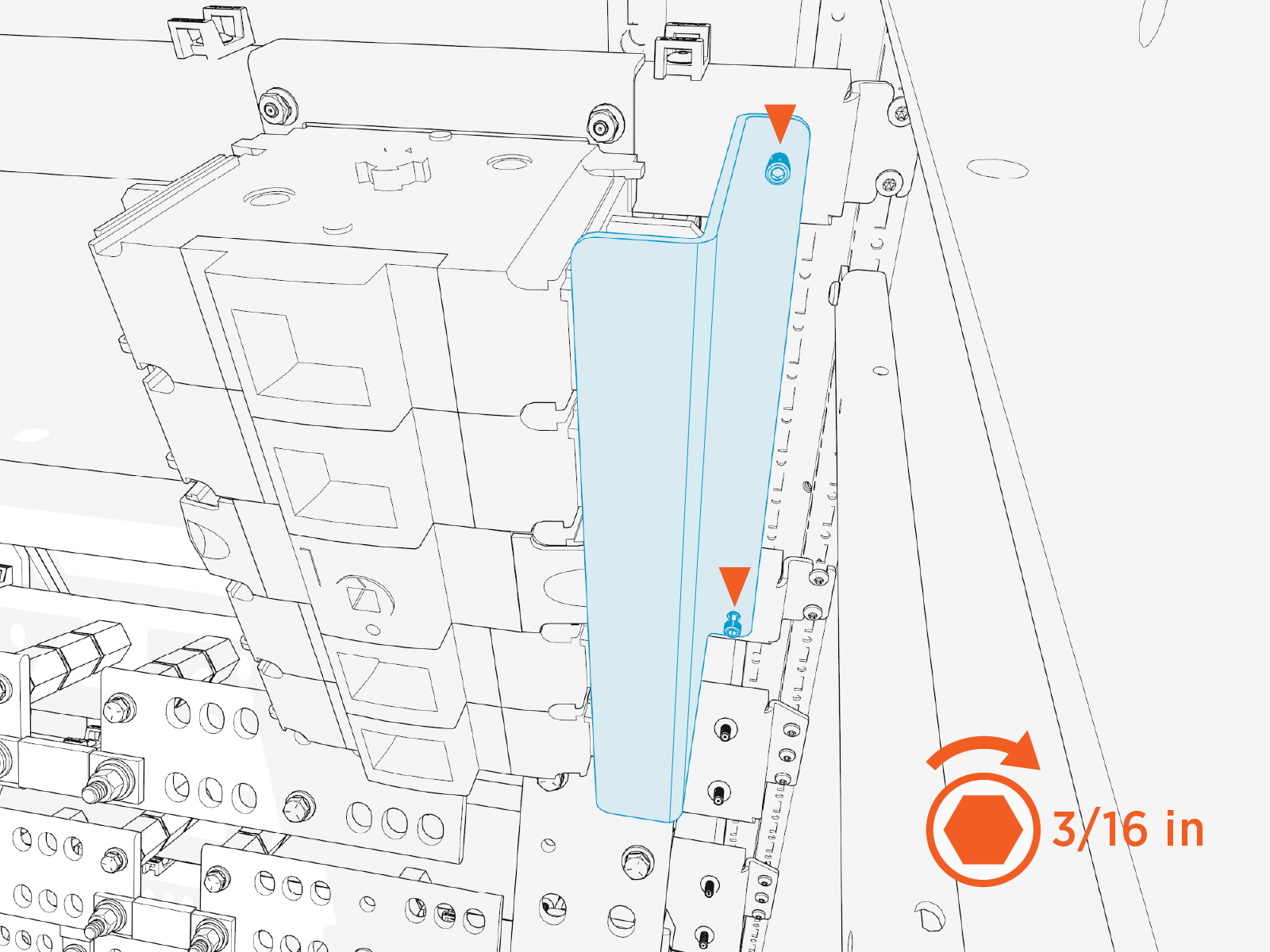
Install Disconnect Switch Safety Shield
To install disconnect switch safety shield, complete the following steps:
-
Peel off the protective plastic from the front and back of each shield.
-
Install the disconnect switch safety shield. Torque the captive screws (x2) to 2.8 Nm (25 in-lb).
Install Disconnect Switch Handle
To install disconnect switch handle, complete the following steps:
-
Slide the following components onto the disconnect switch shaft:
-
Rubber o-ring
-
Disconnect shaft safety tag
-
Rubber o-ring
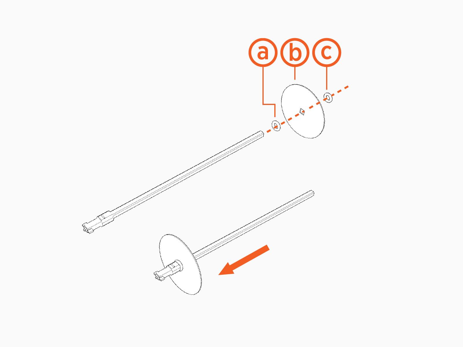
-
-
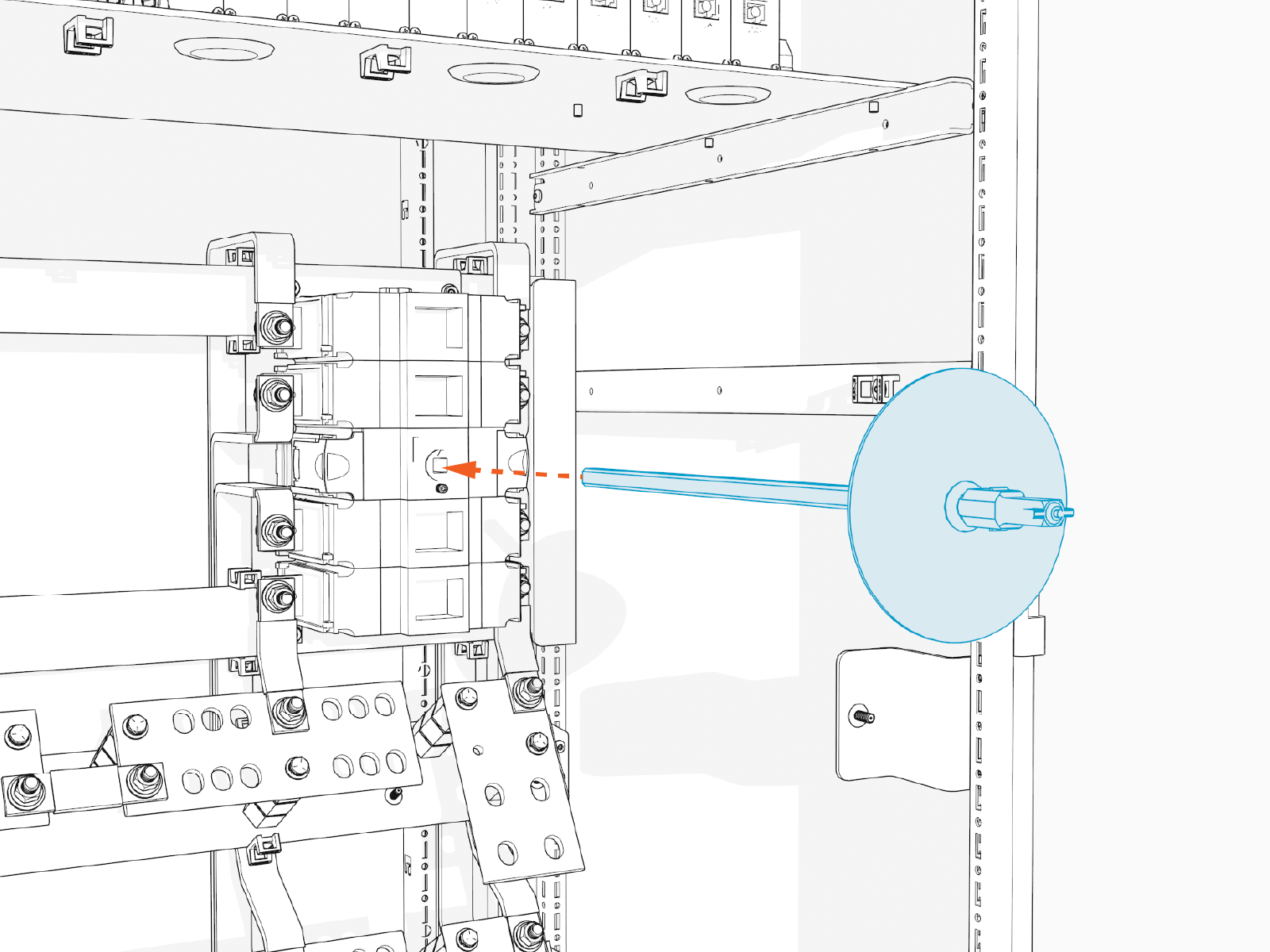
Insert the disconnect shaft into the front of the disconnect switch.
-
Tighten the disconnect switch shaft set screw. Hand tighten.
The set screw is angled upwards.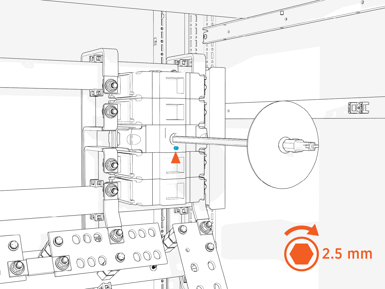
-
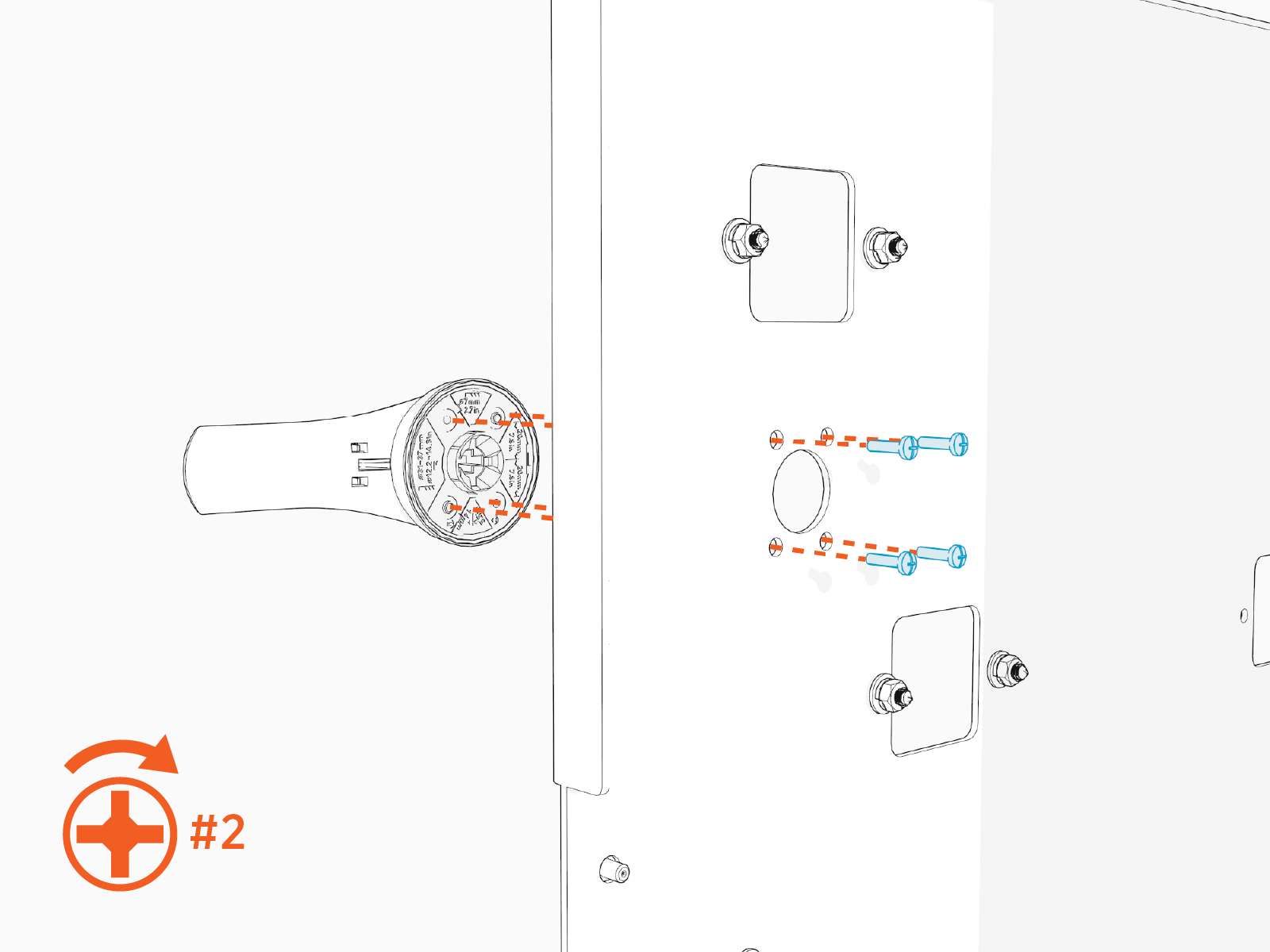
Inspect the disconnect switch handle. Ensure the rubber gasket is in place on back side of the handle.
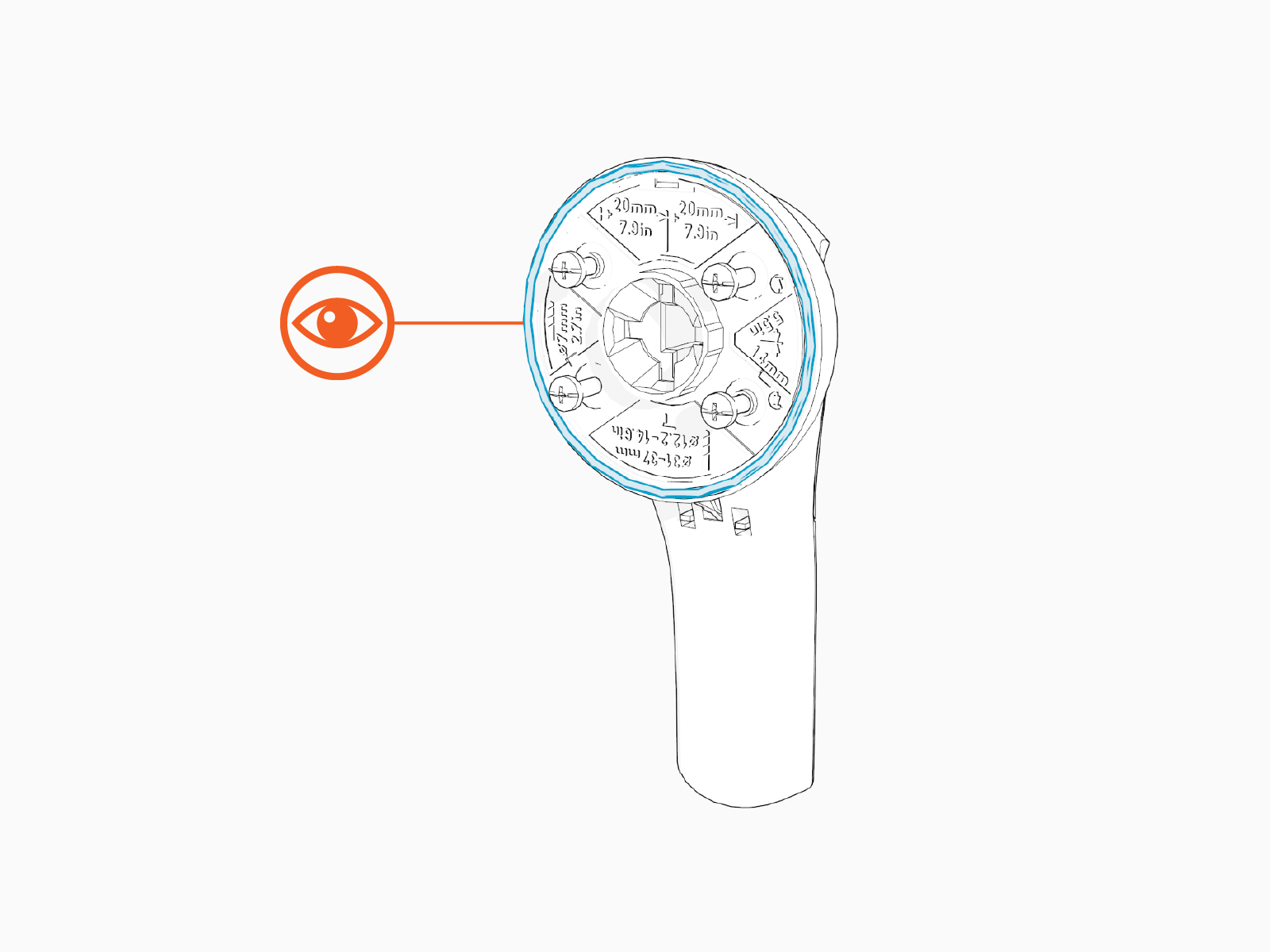
-
Secure the disconnect handle to the dead front cover with Phillips head screws (x4). Hand tighten.
-
This concludes the Second Input Kit installation. Return to the Power Hub installation procedure Prepare for Mount.
