Prepare for Installation
This section describes how to prepare for the installation.
Check Site Readiness
To ensure that the site is ready for installation, refer to the instructions below:
Civil and Mechanical Readiness
Ensure that:
-
The installation site (i.e., concrete pad or concrete surface) meets the conservative stability specifications given in the Express Plus Power Hub Site Design Guide, or has been inspected and approved by a structural engineer for the Power Hub dimensions and weight as given in the Express Plus Power Hub Site Design Guide .
-
The concrete pad is fully cured and smooth.
-
The slope at the installation site does not exceed 20 mm per meter (0.25 in per ft). If necessary, use a grinder or a hammer and chisel to remove any concrete that is not level with the rest of the concrete pad or surface.
-
Four anchor bolts are installed in the concrete at the each installation location specified by the site drawings, and in accordance with instructions given in the Express Plus Power Hub Site Design Guide .
-
The anchor bolt ends protrude 38 mm (1.5 in) above the concrete surface, and they are plumb.
-
The wires and conduits meet the requirements given in the site drawings.
-
The electrical equipment is installed and labeled in accordance with the National Electrical Code (NEC
 National Electric Code) and all applicable requirements of the serving electric utility company and the authority having jurisdiction.
 -
The installation site meets the drainage and clearance guidelines given in the Express Plus Power Hub Site Design Guide .
- Sufficient space is available to use a forklift or other lifting equipment, unpack, remove packing materials, and allow two people to freely move throughout the site.
Electrical Readiness
Refer to the Express Plus Power Hub Site Design Guide for electrical input and output specifications.
Required Tools and Materials
Installing the Power Hub requires at least two people. Additionally, the installer must bring the following tools and materials. These are not provided by ChargePoint.
Use appropriately sized tools to torque fasteners.
Use the given torque values to tighten the fasteners.
Ensure that the tools such as torque tool, multimeter, and Ethernet tester are calibrated.
Tools
|
|
Forklift
|
|
Flat eye web lifting sling
|
|
|
Hard hat |
|
Cut-resistant gloves |
|
|
Safety glasses |
|
Stepladder |
|
|
Cable ties |
|
Drill and drill bits (3.2–6.4 mm (1/8–1/4 in)) |
|
|
Cable puller or fish tape |
|
Measuring tape or other tool to measure height, length, and distance |
|
|
Level |
|
Lock out/tag out equipment |
|
|
Multimeter with CAT III 1000 V ratings, such as Fluke 87V or similar |
|
Ethernet tester such as a Klein Tools VDV526-052 VDV LAN |
|
|
Conduit cutter (to cut up to 2.5 in conduits) |
|
Box cutter |
|
|
Wire cutters, including for Ethernet (Cat6 Shielded Twisted Pair (STP |
|
Wire strippers, including Ethernet (Cat6 STP |
|
|
Lug crimping tool and die |
|
Ethernet (RJ45) connector crimping tool |
|
|
Torque wrench |
|
Torque screwdriver |
|
|
Hex socket set (7/16 in, 9/16 in, 3/4 in, 15/16 in, including deep socket) |
|
Hex wrench set (3/16 in, 8 mm, and adjustable) |
|
|
T25 Torx screwdriver |
|
Flat head screwdriver set |
|
|
Phillips head screwdriver set |
|
Paper towel roll |
|
|
Torque paint pen |
|
Permanent marker |
|
|
Anti-oxidant joint compound and wire pulling lubricant |
|
Dielectric grease |
|
|
Duct seal compound |
|
Industrial vacuum cleaner |
Tightening Torque
| Component | Fastener (Qty) | Tool | Torque Value | |
|---|---|---|---|---|
|
Enclosure Body |
Anchor top nuts (no riser install) |
5/8 in nut (x4 per enclosure) |
15/16 in socket wrench |
94.9 Nm (70 ft-lb) |
|
Anchor bolts (riser install) |
M12 bolts (x4 per enclosure) |
8 mm hex wrench |
94.9 Nm (70 ft-lb) |
|
|
Panels and plates |
Dead fronts |
Captive screws (x2 per panel) |
#2 Phillips screwdriver |
5.6 Nm (50 in-lb) |
|
Gland plate |
T25 Torx screws (x8 per plate) |
T25 Torx screwdriver |
5.1 Nm (45 in-lb) |
|
|
Wire landing |
48 V DC input wire |
Set screw (x1 per wire) |
#2 Phillips screwdriver |
2.8 Nm (25 in-lb) |
|
48 V DC output wire |
Set screw (x1 per wire) |
#2 Phillips screwdriver |
1.7 Nm (15 in-lb) |
|
|
Ground wire lug nut |
1/4 in serrated nut (x1 per lug) |
7/16 in socket wrench |
4.9 Nm (43 in-lb) |
|
|
HV DC |
1/2 in nut (x2 per lug) |
3/4 in socket wrench |
61.6 Nm (45 ft-lb) |
|
|
Buses |
HV DC |
Captive screws (x4 per cover) |
3/16 in hex wrench |
2.8 Nm (25 in-lb) |
Materials
-
Fasteners for securing cabinet to anchor bolts
-
Washers: 5/8 in, ASTM A240
-
Nuts: 5/8 in, hex, ASTM F594 and ANSI
American National Standards Institute B18.22.1 Type A Plain -
Quantity (x4) per Power Hub
-
-
Ground wires, quantity and type as specified by site plan
-
High voltage DC wires, quantity and type as specified by site plan
-
48 V DC wires, quantity and type as specified by site plan
-
Outdoor rated Cat6 Shielded Twisted Pair (STP
Shielded Twisted Pair) Ethernet cables, quantity as specified by site plan -
Cat6 shielded connectors, quantity as specified by site plan
-
High voltage DC lugs
-
Must be Listed lugs
-
Must be nickel, tin, or silver plated copper compression (not mechanical) lugs
-
Nickel plated is recommended
-
-
Long tongue with two holes
-
13 mm (1/2 in) hole size
-
44.5 mm (1-3/4 in) hole spacing
-
Maximum tongue width 19 mm (3/4 in)
-
Quantity as specified by site plan
-
-
Ground wire lugs
-
Must be Listed lugs
-
Must be nickel, tin, or silver plated copper compression (not mechanical) lugs
-
Nickel plated is recommended
-
-
Single hole
-
M6 hole size
-
Maximum tongue width 19 mm (3/4 in)
-
Quantity as specified by site plan
-
-
Weatherproof sealant
Power Hub Packages
|
Product |
Package Detail |
Dimensions (L x W x H) |
Weight |
|
Power Hub |
Enclosure vertically bolted to pallet, wrapped in cardboard |
1.22 x 1.01 x 2.18 m (48 x 40 x 86 in) |
240 kg (530 lbs) |
|
Riser Kit |
Cardboard box |
0.79 x 0.22 x 0.11 m (31 x 8.5 x 4.5 in) |
7 kg (15.5 lb) |
|
Second Input Kit |
Cardboard box |
0.89 x 0.38 x 0.23 in (35 x 15 x 9 in) |
12.7 kg (28 lb) |
Unpack the Power Hub
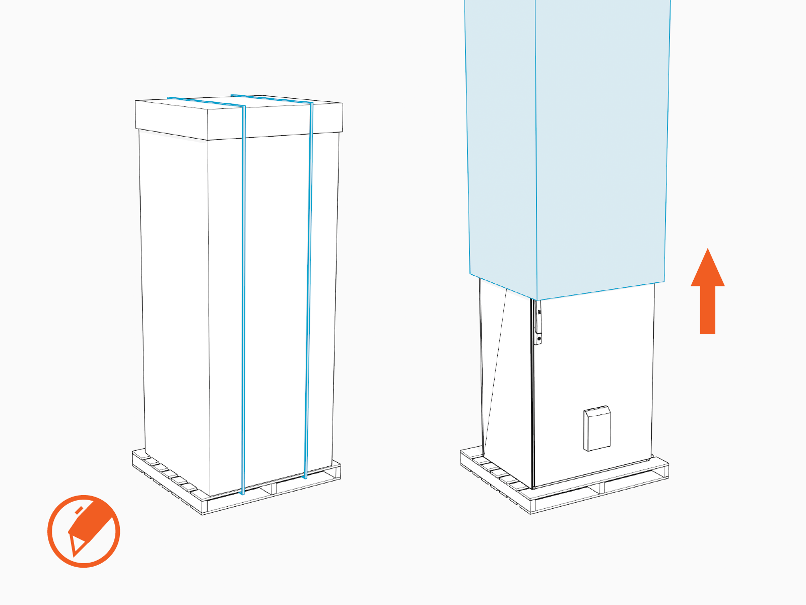
The Power Hub ships vertically bolted to a pallet, and packaged in a cardboard wrap secured with straps. Before unpacking, use a forklift to transport the packaged Power Hub close to the installation site.
-
Remove the cardboard wrap.
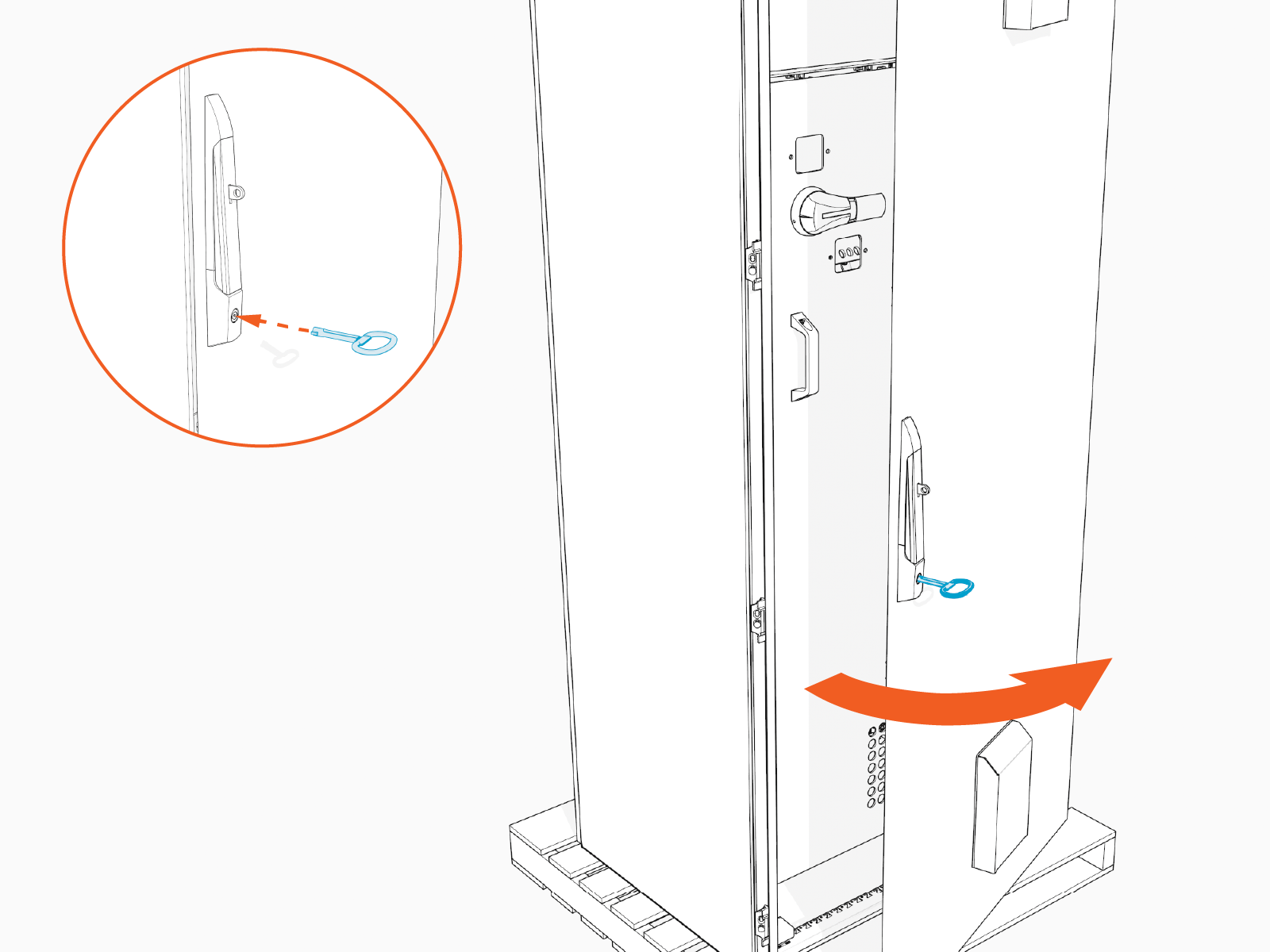
-
Locate the cabinet key zip-tied to the cabinet door. Remove the key from the door. Unlock and open the cabinet door.
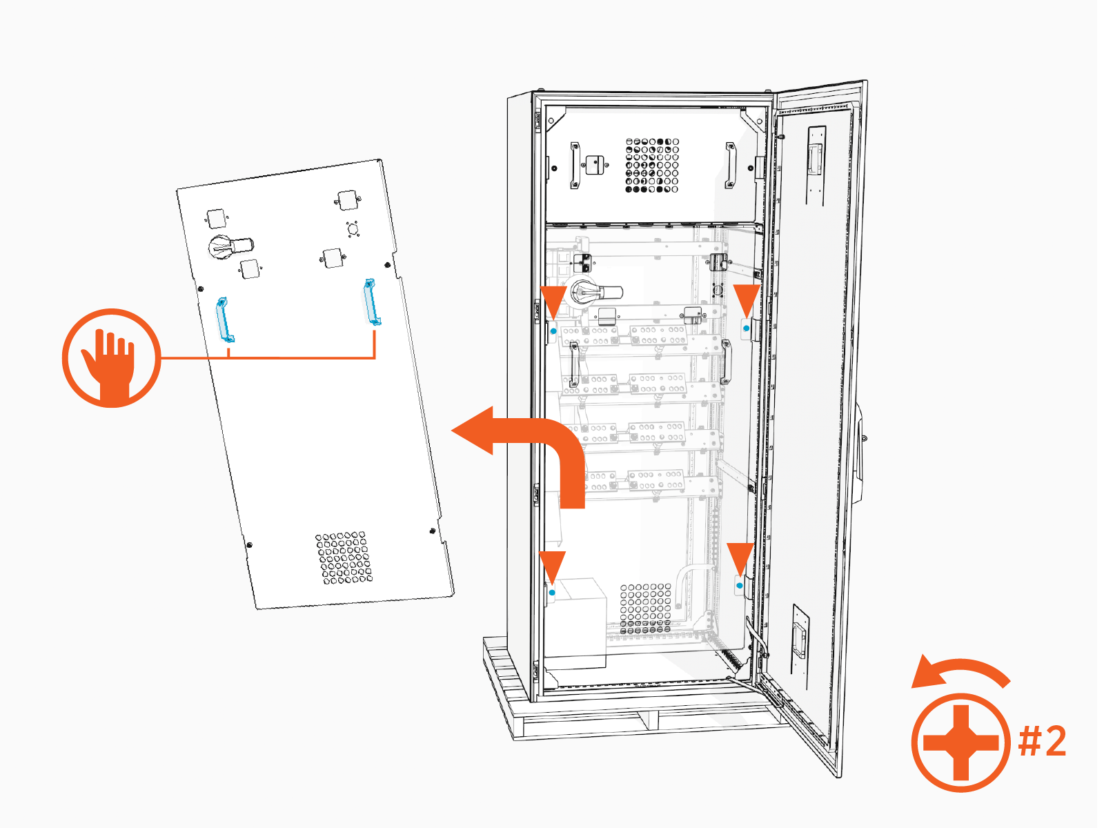
-
Remove the high voltage cabinet dead front. Loosen two captive screws (x2) on the dead front until they disengage. Use the handles to lift the dead front up and off. Set it aside in a safe location.
-
Remove the low voltage cabinet dead front. Loosen two captive screws (x2) on the dead front until they disengage. Use the handles to lift the dead front up and off. Set it aside in a safe location.
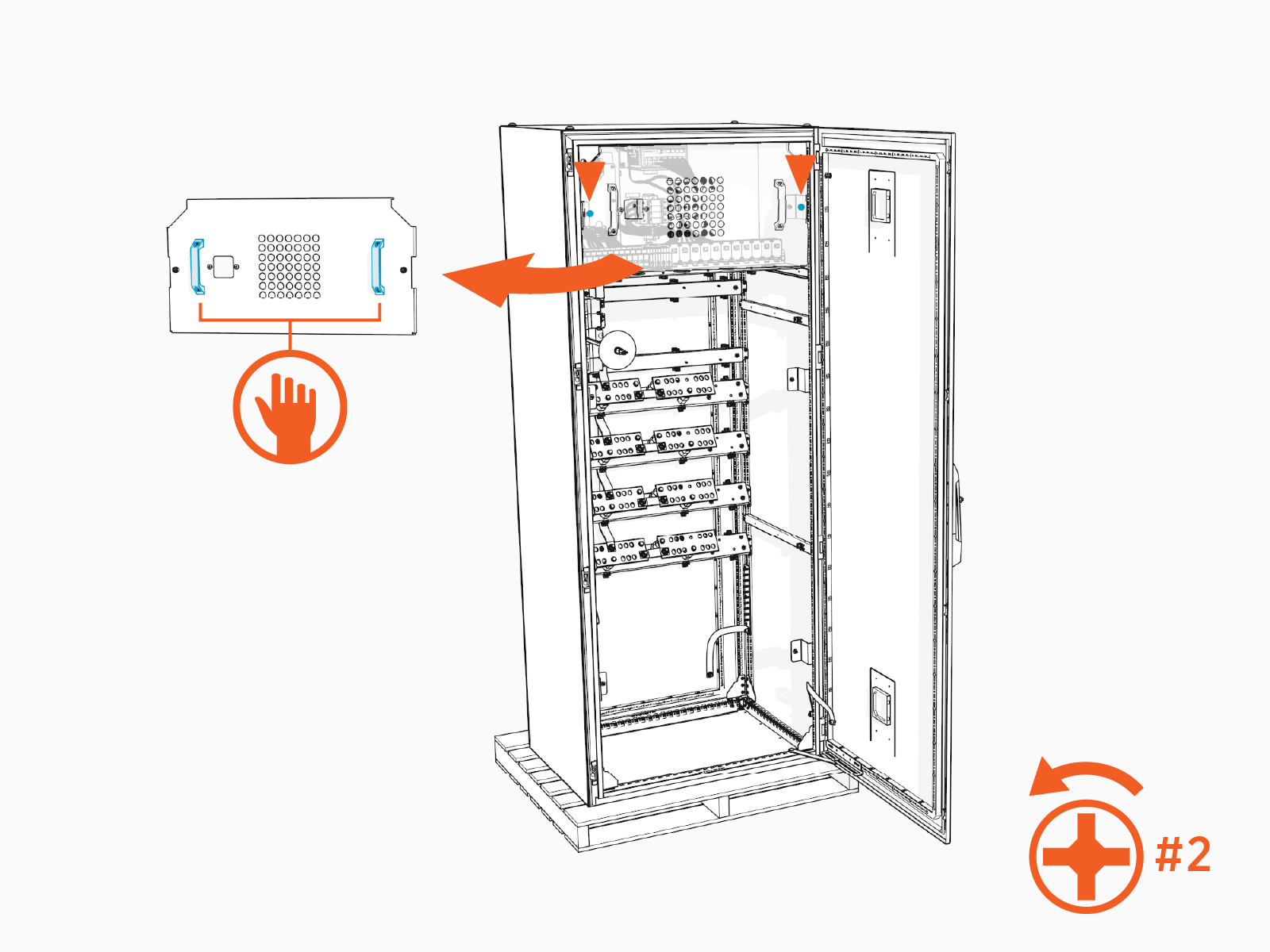
-
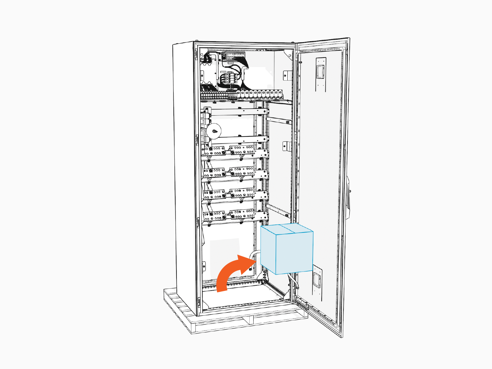
Retrieve a cardboard box of installation parts from within the cabinet.
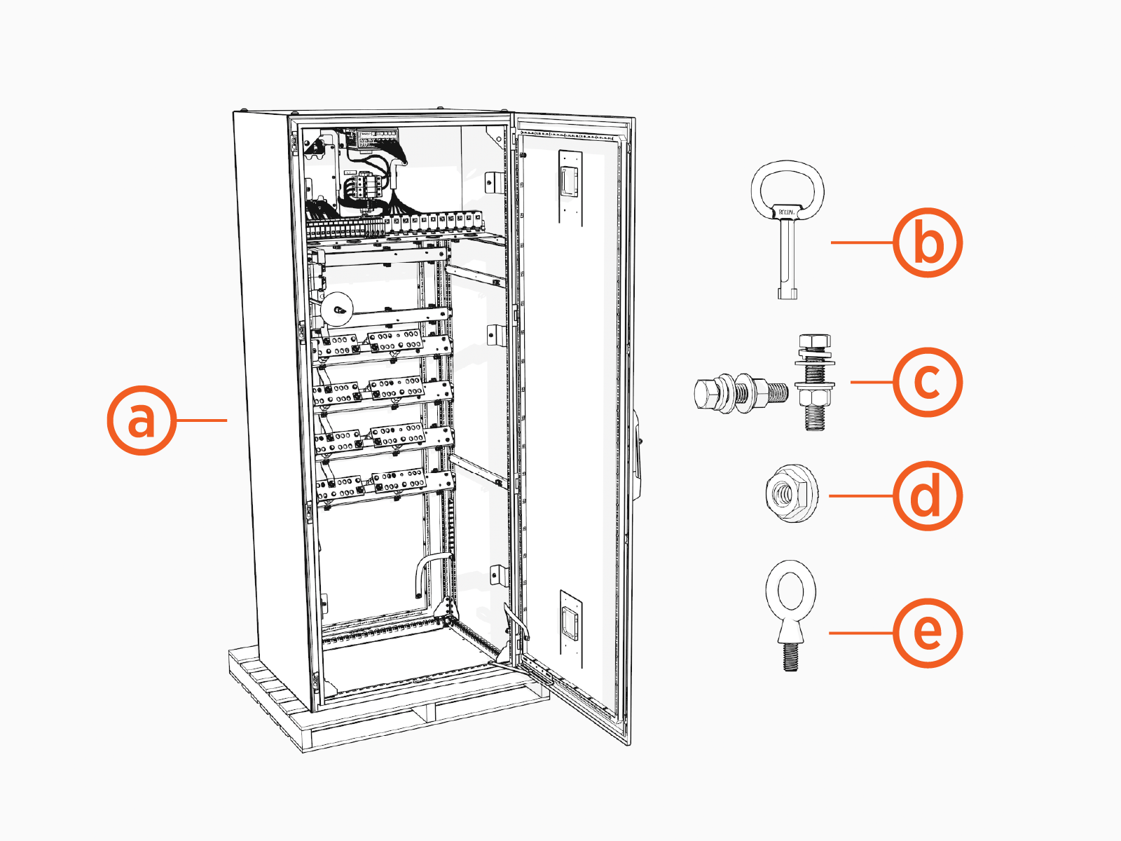
Review Power Hub Parts
Ensure all contents shown below are present.
-
Power Hub cabinet
-
Key
-
High voltage lug fasteners (x40)
-
1/2 x 2-1/4 inch bolt
-
1/2 inch lock washer
-
1/2 inch flat washer (x2)
-
1/2 inch Belleville washer
-
1/2 inch hex nut
-
-
Ground lug fasteners (x12)
-
1/4 inch serrated flange nut
-
-
M12 Eye bolts (x4)
Disconnect Power
- Before any procedure, disconnect the power.
- Follow local code and site lockout/tagout procedure to de-energize the station.
- Wait for energy to dissipate (approximately five minutes).
- Keep power off until all covers and panels are reinstalled and the work is complete.
-
Disconnect power at the Power Block that feeds the Power Hub.
Follow standard practice and local code to de-energize the applicable circuit and lock out/tag out the disconnect before proceeding.

-
Use a multimeter to test that power is off.
