Introduction
This section provides an introduction to the ChargePoint® Express Plus Power Hub.
Power Hub and Express Plus

The Power Hub is a component of the Express Plus product family. Express Plus is a modular solution for scalable fast charging of electric vehicles, comprising the following product components:
-
Power Block: Power cabinet that converts AC power to DC power. Supplies DC output power to Power Link 1000s, either directly or through a Power Hub. Each Power Block has two DC outputs.
-
Power Hub: Distribution cabinet that enables one or more Power Blocks to distribute charging power to more Power Link 1000s than a single Power Block could support by itself.
-
Power Link 1000: Dispenser for electric vehicles, available in single or dual input variants. Can support up to two output cables or automatic connection devices with sequential or simultaneous charging.
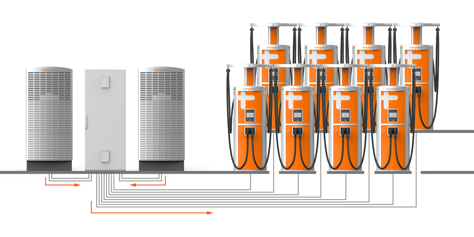
The Power Hub is used in fleet charging architectures. Each Power Hub can accept input power from up to two Power Blocks, and then distribute that power to as many as eight Power Link 1000s (two or four of which can actively charge at a time, depending on configuration). The configuration shown above can charge two vehicles at a time and supports sequential charging of 16 vehicles.
Internal disconnect switches enable high voltage shutoff between the Power Hub and each of its connected Power Blocks. Low voltage and Ethernet connectivity are fed from the Power Blocks to the Power Hub, and from the Power Hub to Power Link 1000s.
Power Hub Installation Configurations
The Power Hub supports multiple configurations to meet diverse installation requirements, as described in this section.
Riser Kit
The Power Hub can be installed on a riser if additional space beneath the Power Hub is needed to accommodate conduit fittings or cable glands. The riser raises the Power Hub cabinet off the ground by 100 mm (4 in). The Power Hub Riser Kit is ordered and shipped separately from the Power Hub.

Single or Double Input
The Power Hub ships equipped for high voltage DC inputs from one Power Block, denoted Power Block Left. This default configuration includes hardware for landing high voltage DC cables from Power Block Left, and a disconnect switch for high voltage DC power shutoff from Power Block Left.
The Power Hub can be configured to accept high voltage inputs from a second Power Block, denoted Power Block Right, by installing a Second Input Kit. The Second Input Kit includes hardware for landing high voltage DC input cables from Power Block Right, as well as a second disconnect switch for power shutoff from Power Block Right. Adding a second Power Block to a Power Hub doubles the potential power available to share across connected Power Link 1000s.
The Second Input Kit must be ordered separately, and is field installed into the Power Hub. Installation of the Second Input Kit can be performed solely from the front side of the cabinet; however it is more easily installed when there is both front and rear acess to the cabinet. In cases where the rear clearance of an installed Power Hub is less than 812.8 mm (32 in), it is easiest to install the Second Input Kit prior to mounting the Power Hub into its final location. For example, it may be installed in the field while the Power Hub is still attached to its shipping pallet. For the case in which an installed Power Hub may be connected to a second Power Block at a future time, consider pre-installing a Second Input Kit prior to initial cabinet mount.
The Second Input Kit is ordered and shipped separately from the Power Hub, and is field installed into the Power Hub.
Wire Entry
The Power Hub supports two types of conductor entry:
-
Stub-up entry: The conductor wires enter the Power Hub from underground, through stubbed-up conduits.
-
Surface entry: The conductor wires enter the Power Hub through its rear or sides, through conduits laid on the surface of the concrete.
Wires may be pulled prior to the installation of the Power Hub or after mounting the Power Hub enclosure. This guide follows the approach of pulling wires into the Power Hub after mounting the enclosure.
Split Bus
The Power Hub ships configured as a dual bus system that supports charging of two vehicles at a time, one vehicle per bus. When used with two Power Block inputs, the Power Hub can be configured in a split bus configuration that supports charging of four vehicles at a time. This configuration is achieved by removing a set of bus jumpers from the high voltage DC output terminals. Jumper removal is done in the field from the front of the cabinet.
The Power Hub must have two Power Block inputs to be used in split bus configuration.
Power Hubs with a split bus configuration should be tagged as "split bus" on the site plan.
Power Hub Exterior Parts
The following provides an overview of the Power Hub exterior parts.

-
Front door
-
Door handle with lock
-
Air vents
-
Low voltage cabinet dead front
-
High voltage cabinet dead front
-
Disconnect handle, left
-
Disconnect handle, right
The Power Hub does not ship with a right disconnect handle. It is field installed if the Power Hub connects to two Power Blocks.
Power Hub Interior Parts
The following provides an overview of the Power Hub interior parts.

-
48 V DC output terminals
-
48 V DC input terminals
-
Ethernet ports
-
Disconnect switch, left
-
High voltage DC input terminals, left
-
Disconnect switch, right
The Power Hub does not ship with a right disconnect switch. It is field installed if the Power Hub connects to two Power Blocks.
-
High voltage DC input terminals right
The Power Hub does not ship with these terminals installed. They are field installed if the Power Hub connects to two Power Blocks.
-
High voltage DC output terminals
-
Ground studs
-
Gland plate
Express Plus Guides
Access documents at ChargePoint Product Reference Documentation.
|
Document |
Content |
Primary Audiences |
|
Datasheet |
Full station specifications |
Site designer, installer, and station owner |
|
Site Design Guide |
Civil, mechanical, and electrical guidelines to scope and construct the site |
Site designer or engineer of record |
|
Concrete Mounting Template Guide |
Instructions to embed the charging station template in a concrete pad with anchor bolts and conduit placement (these may also be included in the Site Design Guide) |
Site construction contractor |
|
Surface Conduit Entry Kit Guide |
Instructions for sites where conduit cannot be run underground |
Installer |
|
Construction Signoff Form |
Checklists used by contractors to ensure the site is correctly completed and ready for product installation |
Site construction contractor |
|
Installation Guide |
Anchoring, wiring, and powering on |
Installer |
|
Operation and Maintenance Guide |
Operation and preventive maintenance information |
Station owner, facility manager, and technician |
|
Service Guide |
Component replacement procedures, including optional components |
Service technician |
|
Declaration of Conformity |
Statement of conformity with directives |
Purchasers and public |
