Maintenance
The station needs preventive maintenance over its lifetime.
ChargePoint’s network connection monitors system health and alerts you when corrective maintenance might be required.
Customers who have purchased the ChargePoint Assure Pro maintenance service are entitled to one annual preventive maintenance service for their stations. An authorized ChargePoint Service Technician should perform this service. For more information on becoming a ChargePoint certified installer or service technician, visit https://www.chargepoint.com/partners/training-certification.
Site Manager Responsibilities
The site or facility manager has a few duties for general site maintenance:
-
Ensure stations are free of debris and nothing is blocking the front and rear vents.
-
Clear away snow and other substances to maintain the clearances specified in the CP6000 Site Design Guide.
-
Check each station monthly for vandalism or damage. If the station shows signs of vandalism , contact ChargePoint for replacement signs. If the station appears damaged, contact ChargePoint for a service visit.
-
Check each charging cable monthly for any signs of wear or damage. If a cable appears damaged, contact ChargePoint for a service visit.
Preventive Maintenance
Risk of shock
-
Before any procedure, the technician must disconnect the power.
-
Follow local code to de-energize the applicable circuit and lock out/tag out the disconnect before proceeding. Use a multimeter to test that power is off.
-
Keep power off until the top cap is correctly reinstalled and the work is complete.
Failure to follow these instructions can result in serious injury, loss of life, or property damage.
Station Components

-
Cable Management Kit (CMK
 Cable Management Kit)
 -
Station and Eichrecht display
-
Meter display and type labels
-
Charging cables
-
Status LEDs
-
Type 2 holster
-
Type 2 socket
Annual Maintenance
Perform the following maintenance every year:
-
Use a damp, lint-free cloth to wipe down the exterior surfaces, including the cables, outer surfaces of the connector (plug at end of cable), and display.
-
Inspect the exterior for any signs of damage. If you find any, contact ChargePoint.
-
Inspect exterior vinyl signs for marks or fading. Contact ChargePoint for replacement signs, if needed.
-
Inspect charging cables:
-
Check the charging cables and connectors for any sign of damage. If you find any damage, power the station off, advise the site manager to keep it off and contact ChargePoint.
-
For stations with a cable management kit (CMK
Cable Management Kit), check that the charging cables operate smoothly by fully extending and retracting. If you find limited motion or retraction, contact ChargePoint.
-
-
Inspect sockets:
-
Check the sockets for any sign of damage. If you find any damage, power the station off, advise the site manager to keep it off and contact ChargePoint.
-
-
Reset or test Residual Current Device (RCD
Residual Current Device):-
Visit Reset Residual Current Device (RCD) for instructions.
-
-
Check the status lights (a) and the light bar (b). If any lights are not functioning, or you find other issues, contact ChargePoint.
Status Light Color | Operating Definitions | |
|---|---|---|
| Light blue | Plugged in and waiting for capacity due to power management and scheduled charging |
| Blue, pulsing | Charging a vehicle |
| Blue, solid | Charging complete or preparing for vehicle communication after plugging a vehicle in |
| Green | Available and ready to charge |
| Orange, pulsing | Installing software |
| Orange, solid | Online, waiting for a reservation |


|
Status Light Color |
Fault Definitions |
|
|---|---|---|
|
|
Red |
Out-of-service or disabled |
|
|
Yellow, pulsing |
Plugged in but not authorized, reported as blocked |
|
|
White |
Offline |


For assistance, go to chargepoint.com/support and contact technical support using the appropriate region-specific number.
Reset Residual Current Device (RCD)
Before resetting the RCD![]() Residual Current Device, inspect the front of the station and use the applicable procedure below:
Residual Current Device, inspect the front of the station and use the applicable procedure below:
-
If the station has an RCD
Residual Current Device reset door, use Reset Residual Current Device (RCD) - With RCD Reset Door. -
If it does not have an RCD
Residual Current Device reset door but has two access holes on the front panel, use Reset Residual Current Circuit Breaker (RCD) - Without RCD Reset Door.
Reset Residual Current Device (RCD) - With RCD Reset Door
Perform the following steps to reset RCD![]() Residual Current Device for models with RCD
Residual Current Device for models with RCD![]() Residual Current Device reset door:
Residual Current Device reset door:
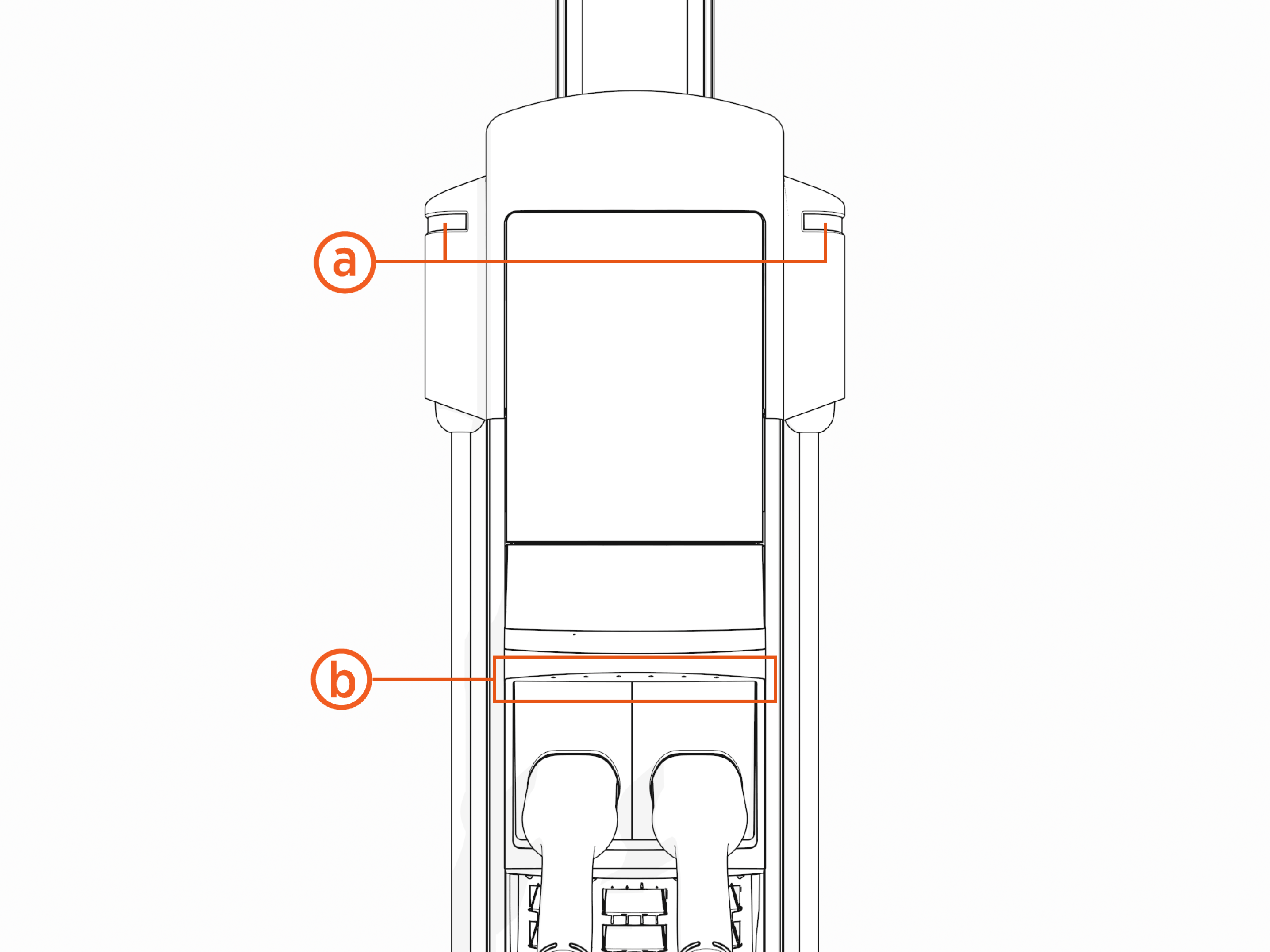
-
Use the provided key to unlock the panel.

-
Gently tilt the access panel (a) away and lift up to remove it from the station.
-
Remove the access tool from the panel (b).
 away and lift up to remove it from the station. Remove the reset tool.")
-
Insert the access tool (b) into the RCD
Residual Current Device reset activator.If the station is configured for a single port, insert the access tool into the RCD Residual Current Device reset activator on the right side.
If you do not have the access tool, use a 9 mm (or a 3/8 in) flat head screwdriver to adjust the reset activator. into the RCCB/RCBO reset activator.")
-
Use the access tool to turn the activator clockwise to the Test position (c) when testing the breaker.
RCD Test Position
 counter clockwise to turn the RCCB off.")
Turn the activator clockwise to turn the RCD
Residual Current Device to the off (0) position (d).RCD Off Position
 counter clockwise to turn the RCCB off.")
-
Use the access tool to turn the activator counter clockwise to turn the RCD
Residual Current Device on (1) again. during this process.")
-
Place the access tool back in the access panel.
-
Align the tabs along the bottom edge of the panel with the slots on the station and tilt the access panel in place.

-
Use the provided key to lock the panel.

Reset Residual Current Circuit Breaker (RCD) - Without RCD Reset Door
Perform the following steps to reset RCD![]() Residual Current Device for models without RCD
Residual Current Device for models without RCD![]() Residual Current Device reset door:
Residual Current Device reset door:
-
Gently insert an 8 mm flat blade screwdriver (a) through one of the two holes (b) in the front panel.
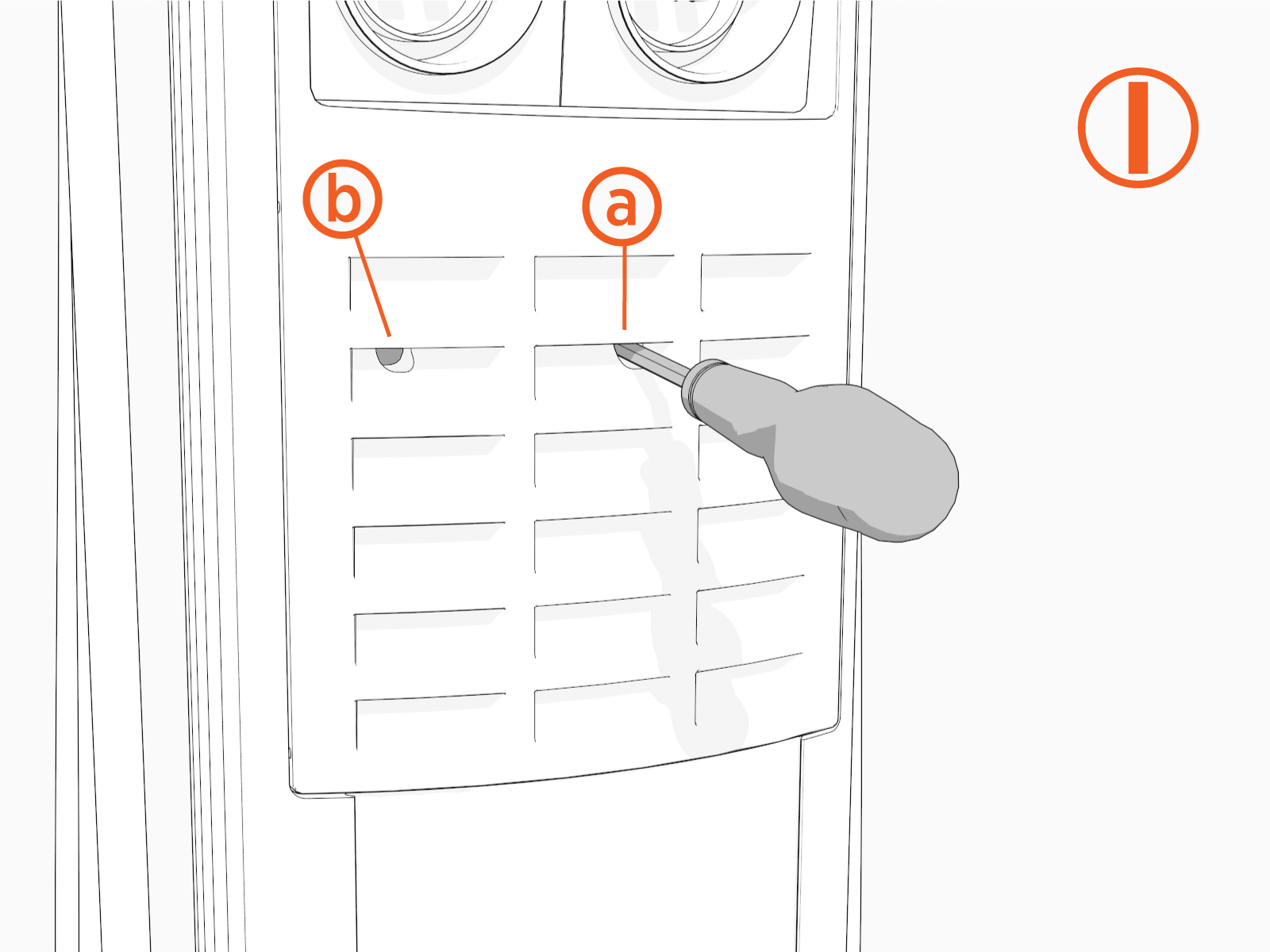
-
Insert the screwdriver (a) at an angle to access the right RCCB
Residual Current Circuit Breaker. 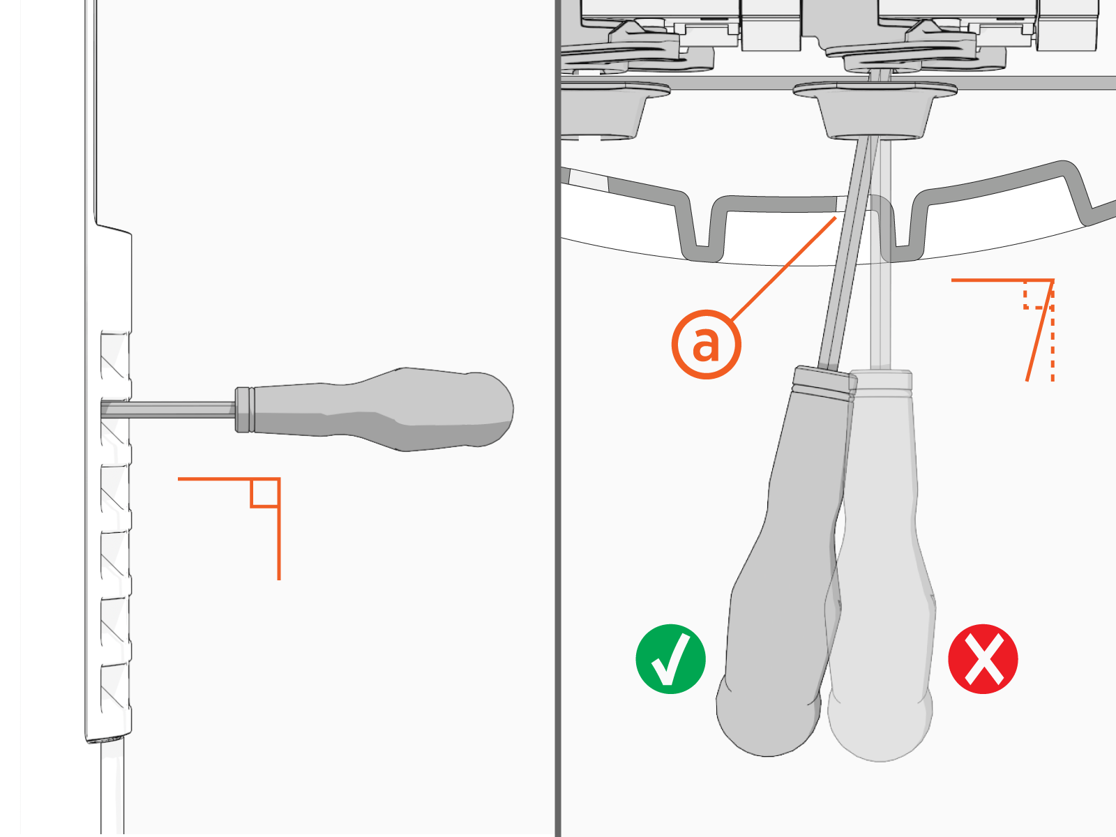
-
Use the screwdriver to turn the activator (c) clockwise to turn the RCCB
Residual Current Circuit Breaker (d) off.
-
Use the screwdriver to turn the activator counter-clockwise to turn the RCCB
Residual Current Circuit Breaker on again. The activator passes over the Test button (e) during this process. Red indicates the power is ON. Green indicates the power is OFF.
 -
If both ports are active, insert the screwdriver straight through the front panel (f) to access the left RCCB
Residual Current Circuit Breaker. 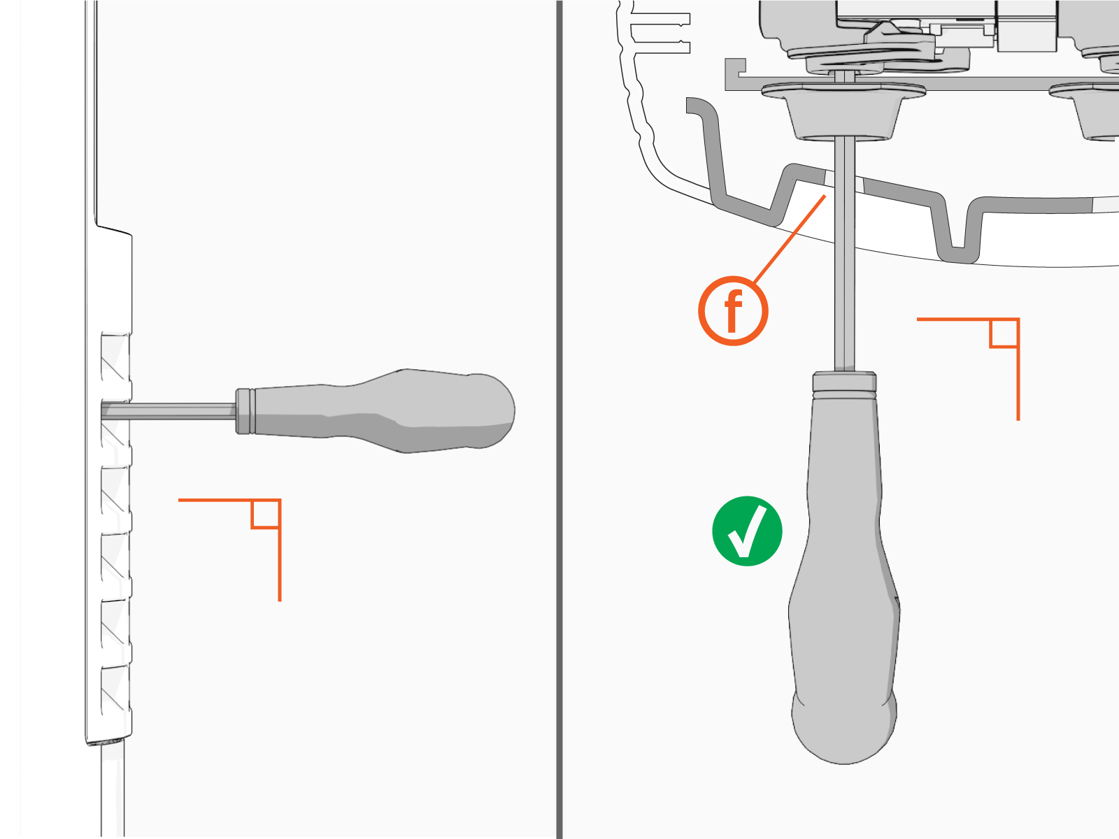
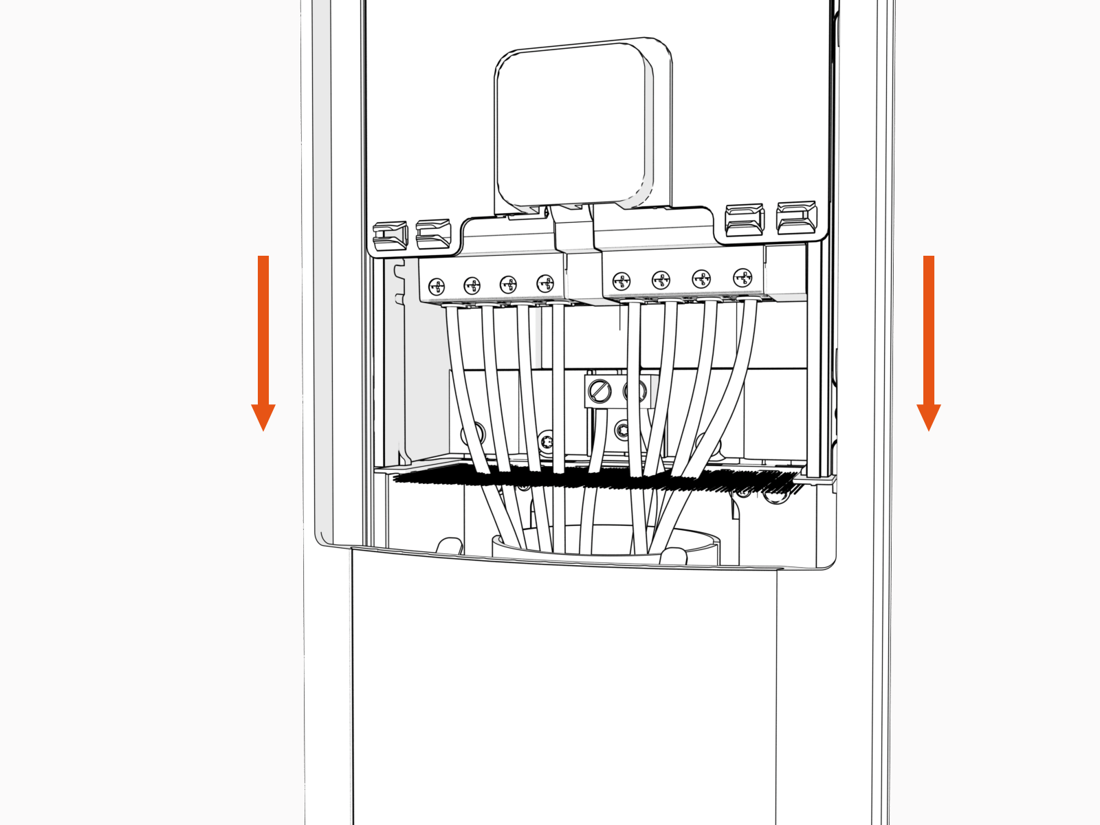
-
Slide the power plate cover down.