Civil and Mechanical Design
Use the following guidance to design the civil and mechanical aspects of the site.
Each charging station can be installed attached to a wall or on a concrete pedestal with or without a Cable Management Kit (CMK![]() Cable Management Kit). The pedestal can be mounted on a newly poured pad or an existing concrete surface.
Cable Management Kit). The pedestal can be mounted on a newly poured pad or an existing concrete surface.
Component Dimensions and Weights
Each CP6000 charging station can be mounted on a pedestal or on a wall with or without a Cable Management Kit (CMK![]() Cable Management Kit). The station is a vertical enclosure with the weights and dimensions shown as follows.
Cable Management Kit). The station is a vertical enclosure with the weights and dimensions shown as follows.
|
Component |
Approximate Weight |
|---|---|
|
Head assembly with two 5.5 m (8 ft) charging cables installed |
19 kg (42 lb) |
|
Head assembly with two 10 m (33 ft) charging cables installed |
23 kg (50 lb) |
|
Head assembly with two sockets |
14 kg (30 lb) |
|
Pedestal enclosure |
20 kg (44 lb) |
|
Wall mount enclosure |
11 kg (25 lb) |
|
Top cap |
2 kg (3 lb) |
|
CMK |
18 kg (40 lb) |
|
CMK |
25 kg (52 lb) |
|
CMK |
32 kg (70 lb) |
|
SEVC |
4 kg (8 lb) |
|
SEVC |
5 kg (10 lb) |
|
SEVC |
6 kg (12 lb) |
Pedestal Mount with CMK

Pedestal Mount without CMK (Socketed)
")
Wall Mount with CMK

Wall Mount without CMK (Socketed)

Concrete Pad Specifications
The concrete pad must either be designed to be site-specific or must meet the specifications below. In some extreme conditions, a larger pad may be required. For sites with less stringent seismic, soil, or wind conditions, a smaller pad might be possible.
Conservative stability specifications for the CP6000 are listed below for the following design scenarios:
-
150 mph wind, high seismic, Class 3 Soil
-
150 mph wind, high seismic, Class 4 Soil
-
150 mph wind, high seismic, Class 5 Soil
-
125 mph wind, high seismic, Class 3 Soil
-
125 mph wind, high seismic, Class 4 Soil
-
125 mph wind, high seismic, Class 5 Soil
All scenarios assume the following:
-
Must not be installed in asphalt
-
Minimum concrete rating 3500 PSI
-
Mounting surface must be smooth
-
All-threaded M16 anchor bolts are embedded 150 mm (6 in) into the concrete pad and are made of ASTM F1554 Grade 36 carbon steel and hot dip galvanized (HDG
 Hot Dipped Galvanized).
 -
Epoxy anchors can be used (installations in existing concrete) if edge of all concrete openings measure greater than 50 mm (2 in) from the anchor bolt hole.
-
No expanding bolts are used.
Pedestal Mount with Tall CMK and 10m Cable

Wall Mount With Tall CMK and 10m Cable

Socket and 5.5m Cable Attached
For CP6000 installations of Socket and 5.5m Cable SKUs, the concrete block must measure at least 600 mm width x 600 mm length x 600 mm thickness (24 in x 24 in x 24 in) for all Design Scenarios (1-6), and the anchor bolt embedment into the concrete pad must be at least 150 mm (6 in).
7m cable attached
For CP6000 installations of 7m Cable SKUs, refer to the following table for minimum concrete pad dimensions for each design scenario.
| Design Scenario | Pad Width | Pad Thickness | Design Scenario |
|---|---|---|---|
| 1 | 600 mm (24 in) | 600 mm (24 in) | 1350 mm (54 in) |
| 2 | 600 mm (24 in) | 600 mm (24 in) | 1350 mm (54 in) |
| 3 | 600 mm (24 in) | 600 mm (24 in) | 1350 mm (54 in) |
| 4 | 600 mm (24 in) | 600 mm (24 in) | 600 mm (24 in) |
| 5 | 600 mm (24 in) | 600 mm (24 in) | 600 mm (24 in) |
| 6 | 600 mm (24 in) | 600 mm (24 in) | 600 mm (24 in) |
|
Specification |
CP6000 Short Unit (6 foot CMK |
CP6000 Tall Unit (8 foot CMK |
|---|---|---|
|
Weight |
68 kg (152 lb) |
77 kg (170 lb) |
|
Height x Width |
1.843 m (6.047 ft) |
2.457 m (8.064 ft) |
|
Width |
354 mm (1.161 ft) |
354 mm (1.161 ft) |
|
Frontal Area |
Height x Width |
Height x Width |
|
CG Height |
689 mm (2.26 ft) |
740 mm (2.428 ft) |
|
Anchor bolts size and quantity |
M20 (x4) |
M20 (x4) |
|
Anchor bolts embedment |
6 inch |
6 inch |
Concrete Mounting Template
You must use a ChargePointConcrete Mounting Template (CMT) when installing a new pedestal mount charging station or replacing an existing non-ChargePoint pedestal mount station.
Use a CMT when installing charging stations on existing concrete (on an intermediate floor only).
You must order the CP6000CMT separately, with sufficient lead time before site construction. This kit ships separately from the ChargePointCP6000 charging station.
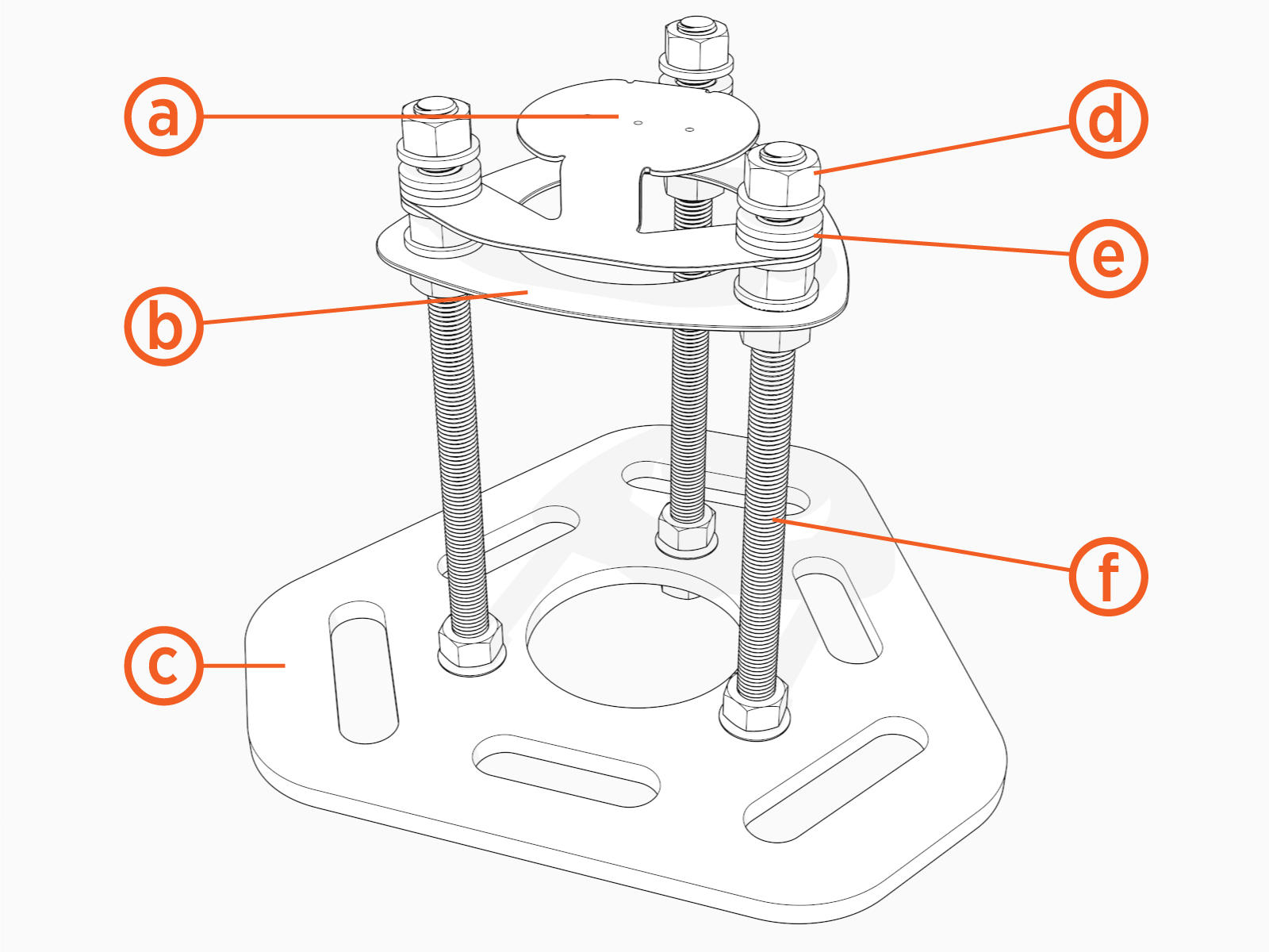
(a) Cable gland bracket
(b) Upper template
(c) Lower template
(d) Nuts (x 15)
(e) Washers (x 18)
(f) Anchor bolts (x 3)
The Concrete Mounting Template kit components you need to use, the tools required, and the installation steps vary depending on the type of installation: new concrete or existing concrete.
CMT - Pedestal Mount with CMK

(a) Wall
(b)CMK![]() Cable Management Kit footprint
Cable Management Kit footprint
(c) Pedestal footprint
(d) Front
(e) Bolt circle
(f) Bolt or anchor
(g) Conduit stub-up within this area (new concrete only)
CMT - Pedestal Mount without CMK

(a) Wall
(b) Pedestal footprint
(c) Front
(d) Bolt circle
(e) Bolt or anchor
(f) Conduit stub-up within this area
Required Tools and Materials
In addition to the CP6000Concrete Mounting Template kit, the site construction team needs:
-
Digging tools (shovel, spade, etc.)
-
Materials to prepare the form for pouring concrete
-
Concrete as specified by site drawings
-
Rebar as specified by site drawings
-
24 mm (1 in) wrench
-
Level
-
Cut-resistant gloves
-
Drill or hydraulic hole punch (if using armored cable)
-
Conduit, ducting, or armored cable in the amounts and types specified by site drawings, that complies with local code (see the rest of this document for conduit sizes and routing)
Installation into New Concrete
-
Trench and excavate an opening to accommodate the wiring conduit and the concrete mounting pad that meets local codes and requirements, per site drawings.
-
Run conduit to each station as needed. If the station needs wired Ethernet access, run Ethernet conduit.
-
Build the form and lay rebar for the foundation.
-
The concrete block must measure at least 600 mm (24 in) on all sides.
-
The conduit stub-up needs to measure between 152 mm (6 in) and 590 mm (23.2 in) above the concrete surface.
It is critical that the conduits are positioned properly and plumb. The tolerance where the conduits enter the station is 2 mm (1/16 in). -
-
Align the CP6000CMT over the conduit stub-ups with the two bolts facing forward and the third bolt to the rear.
-
Slide the CP6000CMT over the conduit stub-ups until the top surface of the template is level with the top surface of the concrete when poured.

-
The bottom of the upper template (a) must align with the surface of the concrete (b).
 must align with the surface of the concrete (b).")
-
Ensure the conduits are plumb.
-
Use a level to check that the CP6000CMT is level from front to back and from side to side.
-
Conduit height (c) must be between 152 mm (6 in) and 590 mm (23.2 in). Each bolt (d) must extend between 60 mm (2-1/2 in) and 100 mm (4 in) above the concrete surface.
 must be between 152 mm (6 in) and 590 (23-1/4 in). Each bolt (d) must extend between 60 mm (2-1/2 in) and 100 mm (4 in) above the concrete surface.")
-
Before pouring concrete, tie the CP6000CMT to rebar to help hold it in place.

-
Pour the concrete.
Make sure the concrete surface between the conduits is completely level and free of any irregularities.
-
Refer to the measurements in this guide and ensure the anchor rod locations are correct before the concrete is dry.
-
Use a level to ensure the bolts are plumb.
You are now ready to install the CP6000 pedestal mount charging station.
Replace an Existing CP4000 or CPF50 Charging Station
CP4000 and CP6000 station pedestals use the same bolt pattern, so the new CP6000 station should fit the existing anchor bolts.
If you are replacing a CPF50 charging station, contact ChargePoint to order a CPF50 Adapter Kit.
Review Civil and Mechanical Design and ensure that the dimensions of the existing concrete slab meet the requirements.
To safely mount a CP6000 charging station, the concrete pad thickness must be at least 600 mm (24 in) and the anchor bolt embedment must be at least 150 mm (6 in). At this thickness, all of the CP6000 mounting bolts must be positioned as follows:
-
At least 380 mm(15 in)from the front edge
-
At least 300 mm(12 in)from the side edges
-
At least 150 mm(6 in)from the rear edge of the concrete slab
Installing on Existing Concrete (replace a charging station with surface or side entry conduit)
To replace a charging station with surface or side entry conduit, the site construction team needs the following:
|
Quantity |
Description |
Purpose |
|---|---|---|
| Electric hammer drill with 12 mm (1/2 in) or larger chuck. | ||
|
1 |
Epoxy adhesive for concrete such as Hilti RE-500 |
Fill drilled holes. |
|
1 |
Electrical cleaning and maintenance aerosol, any angle spray duster, 235 ml (8 oz) |
Clean drilled holes. Note: Compressed air will work. |
|
1 |
Slow spiral round-shank masonry drill bit
|
Drill 19 mm (3/4 in) holes in concrete. Note: The holes must be at least 150 mm (6 in) deep. |
|
1 |
Drill bit for concrete embedded rebar, round
|
Drill 19 mm (3/4 in) hole through rebar. |
|
1 |
Nylon loop handle brush
|
Clean drilled holes. |
|
1 |
Push-on round cap, fits 16 mm (5/8 in) - 17.5 mm (11/16 in) OD, 12.7 mm (1/2 in) inside height, pack of 100 |
Keeps the epoxy inside the drilled holes in situations where the slab is only 150 mm (6 in) deep. |
The consumption rate of these products varies depending on conditions at the installation site.
Installation Instructions
The installation instructions are as follows:
-
Remove the lower template and all nuts and washers from below the upper template.

-
Place the lower template on the concrete and mark the hole locations.
-
When placing the template, consider the charging station’s total footprint.
-
If installing over an existing conduit stub-up or armored cable, position the center of the template around that stub-up / cable.

-
-
Remove the template and drill three 19 mm (0.75 in) diameter holes 250 mm (9.85 in) deep into the concrete.
-
You may need two drill bits: one for the concrete (with the pilot) and another for the rebar (without the pilot). Always start the hole using the standard drill bit, and then switch to the rebar drill bit only if drilling through rebar.
 diameter holes 250 mm (9.85 in) deep into the concrete.")
-
-
Remove all dust from inside the drilled holes using compressed air, a vacuum, or a brush.
-
Remove the bolts from the upper template.
-
Fill each hole with epoxy to about 65 to 75 mm (2.5 to 3 in) below the top of the hole. Continue immediately to the next step because the epoxy sets quickly.
-
Place the upper template over the holes.
-
Insert the bolts through the upper template into the holes.
Rotate the bolts as you insert them. This allows the epoxy to fully coat the threads of the bolts, reducing the amount of trapped air. -
Use a bubble level to ensure the bolts are plumb.
-
Allow the epoxy to cure (depending on cure times recommended by the epoxy manufacturer).
You are now ready to install the CP6000 pedestal mount charging station.
Replace an Existing Non-ChargePoint Charging Station
If an existing charging station (from a manufacturer other than ChargePoint) is already in place at the installation site, complete these tasks:
-
Turn off all power to the station and disassemble according to the original manufacturer’s instructions.
-
Cut away any existing bolts or non-power conduit stub-up to ground level.
-
You may need to plug cut-away conduits at the slab end and disconnect wiring at the other end.
Wall-Mount Specifications
For wall mounted stations:
-
The wall must be smooth, stable, and plumb.
-
The minimum height of the wall must be 1160 mm (45.7 in) above a finished floor.
-
Place wheel stops 900 mm (3 ft) (a) from the wall.
-
The arcs show the usable reach of two charging cable lengths available, 5.5 m (18 ft) (b) and 7 m (23 ft) (c).
Ensure the space between the wall and the charging station is clear and free of debris.
Drainage
Ensure any slopes, walls, or fencing at the site do not trap water around the charging station installation site. The system is only built to withstand water to the height of the armored cable gland bracket.
Clearances
For pedestal installations, the conduit stub-up must be a minimum of 230 mm (9 in) from any obstructions to the rear. This includes other charging stations. Check applicable codes for any additional clearance requirements.
Accessibility
Comply with regional accessibility laws, regulations, and ordinances. The CP6000 charging station must not block ramps or pathways and the height of the interactive display cannot exceed the maximum height as dictated by local laws.
Signage
Refer to local and regional code to design the following elements for the site:
-
Any required re-striping of parking spaces
-
EV
Electric Vehicle or Accessible EV Electric Vehicle signs -
EV
Electric Vehicle or Accessible EV Electric Vehicle paint markings on and around the parking spaces
