Install a Station with a CMK
Prepare the CMK for Mounting
-
Position the Cable Management Kit (CMK
 Cable Management Kit) packaging so that the bottom of the CMK Cable Management Kit is near the base of the pedestal.Do not unwrap the ropes.
 -
Remove and discard the two shipping screws (a).
When you remove the shipping screws, the counterweights are free to move in either direction. To prevent damage or injury, always carry the assembly with the top end higher than the bottom end. -
Remove the foam packaging.
If you are replacing the EV Electric Vehicle PARKING signage with your own custom signage, it is easier to do it now. Refer to the replacement guide for signs available at ChargePoint Product Reference Documentation.

Mount the Brackets and CMK
-
Use the paper mounting bracket template, or hold the back mounting bracket against the wall. The top of the bracket must be approximately 1270 mm (50 in) above grade level.
-
Place a level along the top of the bracket to ensure the holes are accurately aligned.

-
Mark the drill holes:
-
Use the two center holes if mounting to a stud in a wooden wall
or
-
Use the four outer holes if mounting to a concrete wall
-
-
Using a drill and drill bit appropriate for the type of wall, drill the mounting holes. If necessary, insert 6 mm
(1/4 in) - 20 internally-threaded masonry anchors (not included) rated for at least 318 kg (700 lbs) of pull-out force.
-
Align the back bracket with the drill holes. Secure the bracket to the wall using the supplied 6 mm (1/4 in) -20 x 19 mm (3/4 in) hex screws for mounting into the anchors.

-
Run service wiring through 19 mm (3/4 in) conduit.
-
UK only:
-
Mount an installer-supplied 100 mm x 100 mm x 50 mm junction box enclosure with 2 knockouts to the wall.
-
Fasten an installer-supplied 17 mm - 27 mm cable diameter cable gland to the end of the service wiring.
-
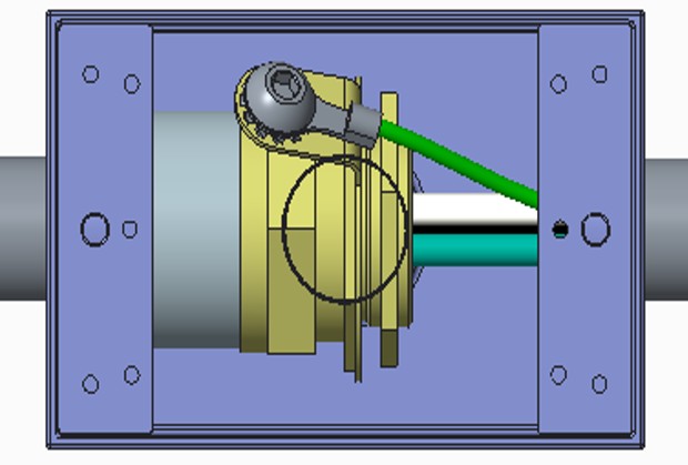
Attach a non-insulated M8 terminal lug to a 6 mm2 (10 AWG
American Wire Gauge) 300 V stranded green/yellow ground wire. -
Use a 5 mm (3/16 in) driver to connect the ground wire to the gland with a M8 x 8mm x 1.25 button head cap screw, M8 external tooth washer, and M8 nut.
-
-
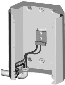
Route the conduit to the hole in the back bracket using a 90 degree elbow cable conduit male to female M25 (or 3/4 in NPT
National Pipe Thread). Run approximately 305 mm (12 in) of service wiring into the bracket.. -
Use a Phillips screwdriver to connect the ground wire to the grounding bar on the back bracket as shown.
-
Position the CMK
Cable Management Kit against the back bracket and hold it in place. -
Position the front bracket so that the wiring opening is in the lower left corner.
-
Being careful not to scratch the installed CMK
Cable Management Kit sign, slide the front bracket down over the CMK Cable Management Kit until it aligns with the back bracket.Route the service wiring out of the way to prevent damage.
-
Route the wiring through the opening in the front of the bracket.
-
Using a #2 Phillips screwdriver, fasten the six 8-32 x 9 mm (3/8 in) screws.

Mount the Station
-
Insert a 6 mm (1/4 in) - 20 x 9 mm (3/8 in) screw (a) into the top center hole on the front bracket using a #2 Phillips screwdriver. Leave the screw protruding approximately 6 mm (1/4 in) to create a 3 mm (1/8 in) gap between the back of the screw head and the bracket.
-
Position the mounting skirt (b) against the back of the main unit as shown.
-
Route the service wiring through the hole in the back of the main unit.
-
Hang the mounting skirt and main unit (c) on the top protruding screw on the bracket.
-
Secure the main unit by inserting the two 6 mm (1/4 in) - 20 x 19 mm (3/4 in) hex screws (d) through the main unit (near the bottom center) and into the bracket as shown. Tighten using a 9 mm (3/8 in) hex driver.

