Civil and Mechanical Design
Use the guidance below to design the civil and mechanical aspects of the site.
The station can be installed attached to a wall, or on a concrete pedestal. The pedestal can be a newly poured pad or an existing concrete surface.
Component Dimensions and Weights
Each CT4000 charging station can be mounted on a pedestal or on a wall with a Cable Management Kit (CMK![]() Cable Management Kit). The station is a vertical enclosure with the weights and dimensions shown as follows.
Cable Management Kit). The station is a vertical enclosure with the weights and dimensions shown as follows.
| Station Configuration | Approximate Weight |
|---|---|
| Single port, wall | 62 kg (136 lb) |
| Dual port, wall | 68 kg (150 lb) |
| Single port, pedestal | 71 kg (155 lb) |
| Dual port, pedestal | 76 kg (168 lb) |
Wall Mount Stations
For wall mounted stations, the wall must be smooth, stable, and plumb. The minimum height of the wall must be 1250 mm (49 in). Place wheel stops (a) 90 mm (3 ft) from the wall. The arc shows the usable reach of the two charging cable lengths available, 5.5 m (18 ft) (b) and 7 m (23 ft) (c).
Pedestal Mount Stations
For newly poured pedestal mounted installations, the mounting surface must be smooth and cannot exceed a slope of 6 mm per 300 mm (0.25 in per ft). The concrete base must measure at least 600 mm (2 ft) on all sides. For installations in existing concrete, epoxy anchors can be used. Consult a civil engineer to ensure sufficient volume and strength of concrete.
There are three basic pedestal base designs:
-
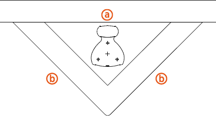
In front of a curb (a) 900 mm (3 ft) x 2 (b)
Area: 0.42 m2 (4.5 ft2)
Volume: 0.26 m3 (9 ft3)
-
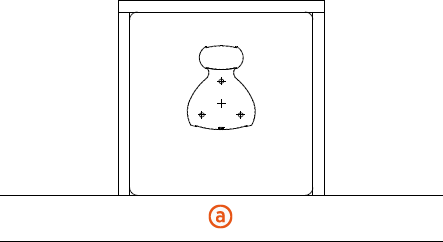
Behind a curb (a) in a planter or berm 600 mm (2 ft) on each side
Area: 0.37 m2 (4 ft2)
Volume: 0.23 m3 (8 ft3)
-
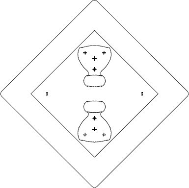
Two stations back-to-back, centered between four spaces
900 mm (3 ft) on each side Area: 0.84 m2 (9 ft2)
Volume: 0.51 m3 (18 ft3)
The pedestal base design can be configured in a variety of ways to serve different parking arrangements. Ensure a sufficient volume of concrete to provide anchoring for the charging station.
-
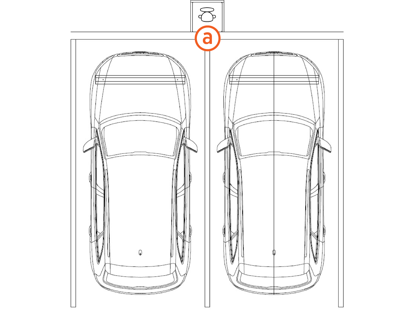
Place the station in a planter or berm between spaces with wheel stops 900 mm (3 ft) from the front of each stall (a).
-
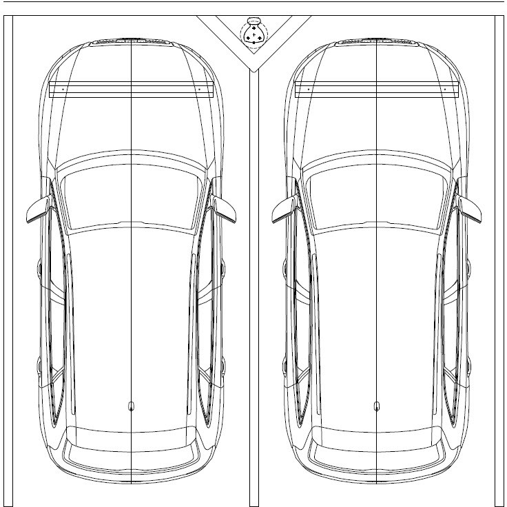
Place the station against the curb between spaces with wheel stops 900 mm (3 ft) from the front of each stall. The base of the charging station can be flush with the parking spaces or at curb level.
-
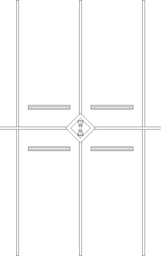
Place two stations back-to-back centered on four spaces with wheel stops 900 mm (3 ft) from the front of each stall. The base of the charging station can be flush with the parking spaces or at curb level.
-
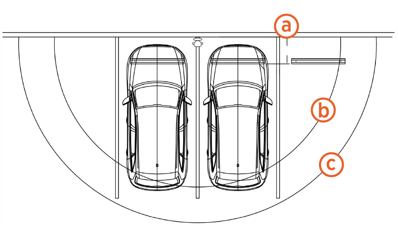
Place a dual holster station centered on the right space. The charging cables reach two vehicles. Place a wheel stop (a) 1220 mm (4 ft) from the center of the charging station. The arc shows the usable reach of the two charging cable lengths available: 5.5 m (18 ft) (b) and 7 m (23 ft) (c). The 7 m (23 ft) cord option is recommended for this configuration. The base of the charging station can be flush with the parking spaces or at curb level. Be sure to install EV
 Electric Vehicle Charging Station signs on both spaces.
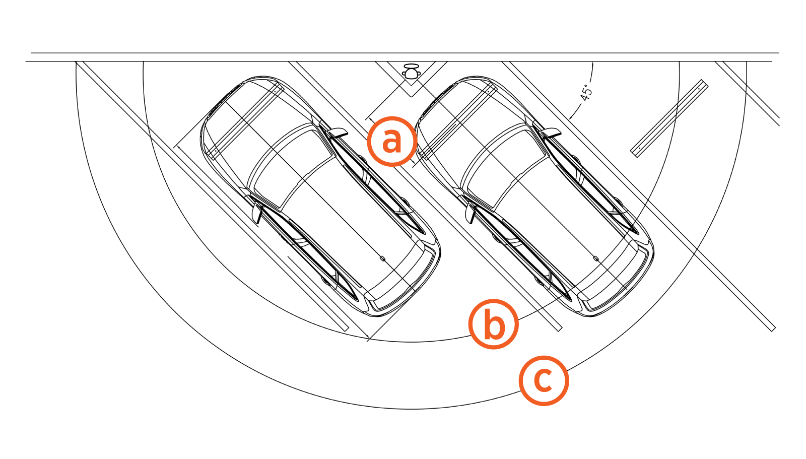
-
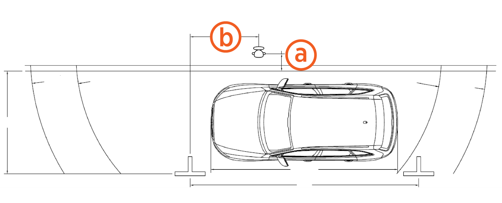
Place a dual holster station centered between two parallel parking spaces, each 6 m (20 ft) long. Place the station (a) 450 mm (18 in) from the curb. A 7 m (23 ft) charging cable is recommended.

-
Place a single holster station for a single parallel parking space 6 m (20 ft) long. Place the station (a) 450 mm (18 in) from the curb, and 1.8 m (6 ft) from the front of the parking space (b).
Ensure any site slopes, walls, or fencing do not trap water around the charging station installation site. The system is only built to withstand water to the height of the conduit stub-up.
For pedestal installations, the conduit stub-up must be a minimum of 230 mm (9 in) from any obstructions to the rear. This includes other charging stations. Check applicable codes for any additional clearance requirements.
Electrical Specifications
For electrical specifications, refer to the CT4000 Installation guide.
Accessibility
To meet the accessibility requirements, the CT4000 charging cables are no more than 1220 mm (48 in) above ground and no more than 254 mm (10 in) away.
This complies with American Disability Act (ADA) requirements if the station is installed at grade. If your installation must comply with ADA standards, or the disability access regulations for other regions, consider this when designing the height of the pad or when planning a wall-mounted installation.
This complies with Europe disability requirements, if the station is installed at grade. If your installation must comply with disability access regulations, consider this when designing the height of the pad or when planning a wall-mounted installation.
Also consider site design factors such as placement of bollards, wheel stops, or other vehicle obstacles when planning charging station access for disabled parking stalls. Check disability access regulations for guidance on the clearances needed for wheelchair access to charging cables and user interfaces.
