Pedestal Mount
This topic describes the preparation of concrete to mount the CT4000 pedestal.
Concrete Preparation
The ChargePoint charging station pedestal mount can be installed either into new concrete or onto an existing concrete surface (on an intermediate floor only). The kit components you need to use, the tools required, and the installation steps vary depending on the type of installation: installation on new concrete or installation on existing concrete.
Concrete Mount Kit
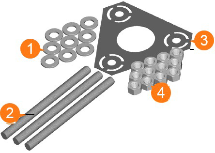
ChargePoint offers an optional CT4000 Concrete Mount Kit for purchase. The kit contains all parts needed to install the CT4000 pedestal mount into new or existing concrete.
|
|
Kit Contents |
|---|---|
|
1 |
9 galvanized washers |
|
2 |
3 hot-dipped galvanized threaded bolts |
|
3 |
1 plastic bolt installation template |
|
4 |
12 hex nuts |
|
5 |
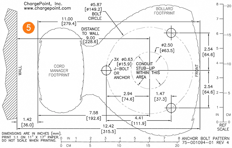
CT4000 installation template with Cable Management Kit footprint |
Installation into New Concrete
Before casting new concrete, review the site for suitability to install a CT4000. The CT4000 requires space behind the power stub-up for the Cable Management Kit (CMK![]() Cable Management Kit). To ensure adequate clearance, refer to the illustrations below and to the CT4000 Installation Template (75-001094-01) included in the Concrete Mount Kit.
Cable Management Kit). To ensure adequate clearance, refer to the illustrations below and to the CT4000 Installation Template (75-001094-01) included in the Concrete Mount Kit.
Ensure compliance with all applicable local codes. Modify these instructions as necessary to align with the codes in effect at your installation location.
-
The concrete block must measure at least 600 mm (2 ft) on all sides.
-
The bolt threads must extend 75 mm (3 in) above the concrete.
-
The conduit must extend 300 to 600 mm (12 to 24 in) above the concrete.
Installation Instructions
To install the pedestal mounting bolts, follow the steps below:
-
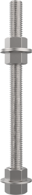
Install two nuts, with two washers captured between them, onto each of the three bolts. Lock them together so the lower end of the upper nut is located 150 to 160 mm (6 to 6.25 in) from one end of the bolt. This sets the length of the exposed threads.
-
Place the plastic bolt installation template over the three bolts. This ensures the relative position of the bolts and that the flange of the pole fits over the bolts.
-
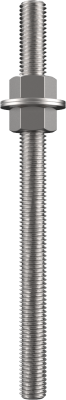
On the opposite end of each bolt, install a nut, a washer, and a nut. Lock the two nuts together so that the lower nut aligns to the bottom of the bolt. This provides retention for the bolt in the concrete.
-
Immediately after pouring the concrete, push the bolts into the concrete 150 mm (6 in) deep.
-
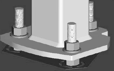
Ensure correct alignment, with the two bolts facing forward and the third bolt to the rear.
-
Ensure that the top 75 mm (3 in) of the bolts remains exposed.
-
Use a bubble level to ensure the bolts are plumb.
-

-
When the concrete is fully set, remove the upper nuts and the washers to install the pedestal’s mounting post.
You are now ready to install the CT4000 pedestal mount charging station.
Installing on Existing Concrete
Review the site for suitability to install a CT4000. The CT4000 requires space behind the power stub-up for the Cable Management Kit (CMK![]() Cable Management Kit). To ensure adequate clearance, refer to the CT4000 Installation Template (75-001094-01) included in the installation kit.
Cable Management Kit). To ensure adequate clearance, refer to the CT4000 Installation Template (75-001094-01) included in the installation kit.
Minimum Requirements
Ensure compliance with all applicable local codes. Modify these instructions as necessary to align with the codes in effect at your installation location.
Review the dimensions of the existing concrete slab. To safely mount a CT4000 charging station, the concrete must be at least 150 mm (6 in) thick. At this thickness, all of the CT4000 mounting bolts must be positioned at least 380 mm (15 in) from the front edge, at least 300 mm (12 in) from the side edges, and at least 150 mm (6 in) from the rear edge of the concrete slab.
If an existing charging station is already in place at the installation site, turn off all power to the station and disassemble according to the original manufacturer’s instructions. Cut away any existing bolts or non-power conduit stub-up to ground level. You may need to plug cut-away conduits at the slab end and disconnect wiring at the other end.
Required Tools and Materials
Electric hammer drill with 12 mm (0.5 in) or larger chuck.
The following table lists and describes consumable items that you will need. The quantity listed in the table is based on installation of one charging station.
|
Quantity |
Description |
Purpose |
|---|---|---|
|
1 |
Epoxy adhesive for concrete such as Hilti RE-500. |
Fill drilled holes. |
|
1 |
Electrical cleaning and maintenance aerosol, any angle spray duster, 235 ml (8 oz) |
Clean drilled holes. Note: Compressed air will work. |
|
1 |
Slow spiral round-shank masonry drill bit, 25 mm (1 in) diameter, 12.5 mm (0.5 in) shank, 255 mm (10 in) drill depth, 300 mm (12 in) length overall |
Drill 25 mm (1 in) holes in concrete. Note: The holes must be at least 150 mm (6 in) deep. |
|
Quantity |
Description |
Purpose |
|---|---|---|
|
1 |
Drill bit for concrete embedded rebar, round 25 mm (1 in) bit size, 12.5 mm (0.5 in) shank diameter, 300 mm (12 in) length overall |
Drill 25 mm (1 in) hole through rebar. |
|
1 |
Nylon loop handle brush, 25 mm (1 in) brush diameter, 75 mm (3 in) length brush, 215 mm (8.5 in) length overall |
Clean drilled holes. |
|
3 |
Push-on round cap, fits 16 mm (5/8 in) - 17.5 mm (11/16 in) OD, 1/2 in inside height |
Keeps the epoxy inside the drilled holes in situations where the slab is only 150 mm (6 in) deep. |
Installation Instructions
-
Install two nuts, with two washers captured between them. Lock them together so the lower end of the upper nut is located 150 to 160 mm (6 to 6.25 in) from the bottom of the bolt. This sets the length of the exposed threads.
-
Place the plastic bolt installation template to mark the hole locations.
-
Remove the template and drill three 25 mm (1 in) diameter holes 150 mm (6 in) deep into the concrete.
-
When locating the template, consider the charging station’s total footprint.
-
It is important that the bolts are parallel after installation. Ensure the drill holes are plumb by using a level to check the angle of the drill after drilling 25 to 38 mm (1 to 1.5 in).
-
If installing over existing buried conduit, position the center of the template around the conduit stub-up.
-
You may need two drill bits: one for the concrete (with the pilot) and another for the rebar (without the pilot). Always start the hole using the standard drill bit, then switch to the rebar drill bit only if drilling through rebar.

-
-
Remove all dust from inside the drilled holes using compressed air, a vacuum, and/or a brush.
-
If the concrete slab is only 150 mm (6 in) deep, insert a plug (such as McMaster product #9753K56) in each hole to keep the epoxy in place until it hardens. Place the plug over the long end of a bolt and then use the bolt to push the plug to the bottom of the hole.
-
Fill each hole with epoxy to about 65 to 75 mm (2.5 to 3 in) below the top. Continue immediately to the next step because the epoxy sets quickly.
Inserting the threaded bolts displaces the epoxy, causing it to fill the holes to the grade level. If the epoxy is below grade level after the next step, add more epoxy. -
Place the plastic concrete bolt installation template over the holes. This ensures the relative position of the bolts and that the flange of the pole fits over the bolts.
-
Insert the bolts through the template, into the holes.
Rotate the bolts as you insert them. This allows the epoxy to fully coat the threads of the bolts, reducing the amount of trapped air.The installation template can be left in place. -
If needed, top the holes with epoxy to grade level.
-
Use a bubble level to ensure the bolts are plumb.
-
Allow the epoxy to cure (depending on cure times recommended by the epoxy manufacturer) before removing the top nuts and washers.
-
Allow the epoxy to fully cure (depending on cure times recommended by the epoxy manufacturer) before applying torque to the nuts.
You are now ready to install the CT4000 pedestal mount charging station.
