Electrical Design
The wall mount CT4000 installation uses surface mount wiring. The pedestal mount CT4000 installation requires service wiring installed underground. (If a site requires surface mounting, contact ChargePoint before beginning work, to obtain an approved installation method.) Conduit and wire size are determined based on the length of runs from the electrical panel to the station location. Service wiring must be run through conduit to comply with local electrical codes. Consult national and local codes or a project engineer to determine the grade, quality, and size of the conduit or cable. The CT4000 Concrete Mount Kit accommodates service wiring through the flare, conduit, or locally appropriate wiring method.
Upstream Components
Charging stations are considered continuous load devices (EVs draw maximum load for long durations); therefore, electrical branch circuits to EV![]() Electric Vehicle chargers must be sized at 125% of the load for North American installations, in accordance with National Electric Code (NEC
Electric Vehicle chargers must be sized at 125% of the load for North American installations, in accordance with National Electric Code (NEC![]() National Electric Code) requirements. (For other regions, refer to local code.) This means that for a maximum 32 A load at 208/240 V output to an electric vehicle, 40 A breakers are required.
National Electric Code) requirements. (For other regions, refer to local code.) This means that for a maximum 32 A load at 208/240 V output to an electric vehicle, 40 A breakers are required.
Wiring must be sized in accordance with NEC![]() National Electric Code code for continuous load devices. Typically, 16 mm2 or 10 mm2 (6 AWG
National Electric Code code for continuous load devices. Typically, 16 mm2 or 10 mm2 (6 AWG![]() American Wire Gauge or 8 AWG
American Wire Gauge or 8 AWG![]() American Wire Gauge) insulated electrical wiring is used, depending upon the distance between the electrical panel and the charging station. The terminal block accepts a maximum of 16 mm2 (6 AWG
American Wire Gauge) insulated electrical wiring is used, depending upon the distance between the electrical panel and the charging station. The terminal block accepts a maximum of 16 mm2 (6 AWG![]() American Wire Gauge) wire.
American Wire Gauge) wire.
When planning multiple EV![]() Electric Vehicle charging stations, it is best practice to segment non-continuous and continuous loads, with all branch circuits for EV
Electric Vehicle charging stations, it is best practice to segment non-continuous and continuous loads, with all branch circuits for EV![]() Electric Vehicle charging on a dedicated electrical panel assembly with adequate circuit breakers. When sizing new electrical panels dedicated for EV
Electric Vehicle charging on a dedicated electrical panel assembly with adequate circuit breakers. When sizing new electrical panels dedicated for EV![]() Electric Vehicle charging, all branch circuits must support continuous load, and the panel rating must be sized for at least 125% of the total load on each leg of a 3-phase panel.
Electric Vehicle charging, all branch circuits must support continuous load, and the panel rating must be sized for at least 125% of the total load on each leg of a 3-phase panel.
- The CT4000 charging station is tested to IEC 61000-4-5, Level 5 (6 kV @ 3000 A) standards. In geographic areas that experience frequent thunderstorms, appropriate supplemental surge protection is recommended to guard against product damage.
- ChargePoint charging stations are UL 916 listed as Energy Management devices and are networked for real time communication to ensure they operate within the provisioned load allowance.
Conduit
The outer diameter of conduit must not exceed the sizes called out in the conduit layout drawing: 63 mm (2.5 in). Conduit stub-ups cannot extend higher than 660 mm (26 in).
For wall mounted stations, flex conduit must be used to bring the wire to the station.
Wiring Requirements
For full product specifications, refer to the CT4000 Datasheet. Using that data, ensure that the installation location is equipped with service wiring that supports the CT4000’s power requirements:
-
AC conductors (L1, L2)
-
Ground conductor
When pulling electrical wiring via conduit for CT4000 pedestal mount, ensure at least 900 mm (3 ft) of coiled wire remains above conduit stub up.
When pulling electrical for wall mounted stations, the conduit and wire must be brought to the location where the stations will be mounted. Flex conduit must be used to bring the wire to the station. Wiring is brought in via the bottom of the CT4000.
Wiring Diagram
240 VAC Single Phase Panel

-
Main Breaker
-
Neutral Bus
-
Ground Bus
-
Neutral
-
L2
-
L1
-
Left L1
-
Left L2
-
Right L1
-
Right L2
-
Ground
-
Left Port
-
Right Port
-
Strip wire 13 mm (0.51 in)
-
Local Service or Subpanel
-
120/240 V AC 1Ø
Bonded Neutral Required
Left and right refers to the left and right ports on the charging station.
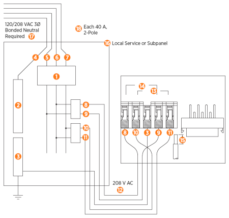
208 VAC Three Phase Panel
-
Main Breaker
-
Neutral Bus
-
Ground Bus
-
Neutral
-
L3
-
L2
-
L1
-
Left L1
-
Left L2
-
Right L1
-
Right L2
-
208 V AC
-
Right Port
-
Left Port
-
Strip wire 13 mm (0.51 in)
-
Local Service or Subpanel
-
120/208 V AC 3Ø
Bonded Neutral Required
-
Each 40 A, 2-Pole
Breaker may be connected to any two lines
Left and right refers to the left and right ports on the charging station.
Grounding Requirements
The CT4000 must be connected to a grounded, metal, permanent wiring system. An equipment- grounding conductor must be run with circuit conductors and connected to an equipment-grounding terminal or lead on the CT4000.
A grounding conductor that complies with applicable codes must be grounded to earth at the service equipment or, when supplied by a separate system, at the supply transformer.
Ensure that a grounding conductor that complies with all applicable codes is properly grounded to earth at the service equipment or, when supplied by a separate system, at the supply transformer.
The voltage of either line, relative to ground, must not fall below 80 volts or a Floating Line Connection error occurs. Because the voltage of either line relative to ground must not be allowed to fluctuate, use only center-grounded systems. Neutral is not used to power the station but must be properly connected to ground, at the panel or transformer, to provide the necessary voltage reference relative to ground.
-
In a Wye system, connect the station to any two lines, as shown.
-
In a Delta system, connect the station to a center-tapped secondary only, where the center tap is bonded and the station is connected to the L1 and L3. This allows voltages to remain constant regardless of other loads that may be using the lines.
Connect to these Systems
To ensure proper operation and compatibility, connect the charging station only to the following electrical systems:
120/240 VAC
-
10 Bonded Neutral Station is connected to L1 and L2.
-
Neutral is not used.

120/208 VAC
-
30 Wye Bonded Neutral Station may be connected to any two lines.
-
Neutral is not used.

120/240 VAC, 30 Delta
-
Center tap grounded
-
Bonded neutral
-
Station must be connected to L1 and L2 only
-
Do not connect any part of the system to L3
-
Neutral is not used
-
Not recommended for new construction

Do Not Connect to these Systems
To prevent equipment damage or malfunction, do not connect the charging station to the following electrical systems:
120/208 VAC 3-phase Wye

-
Ungrounded Floating neutral
-
Voltage of either line to ground is undetermined
-
Neutral is not grounded
120/240 VAC 3-phase Delta, corner-grounded

-
Voltage of any line is not 120 V nominal relative to ground
-
Any system where the center point of the AC power source is not grounded.
