Install Additional Kits
To install additional kits, follow the instructions below:
Install Ethernet to USB Kit
If the site plan indicates the Power Link 2000 must be configured with a hardwire Ethernet connection to a network server, follow procedures in this section to install the Ethernet to USB![]() Universal Serial Bus Kit and the hardwire connection.
Universal Serial Bus Kit and the hardwire connection.
-
Unpack the Ethernet to USB
 Universal Serial Bus Kit. Confirm all parts listed below are present.
For any missing component, contact chargepoint.com/support.

-
Ethernet to USB
Universal Serial Bus module -
M5 star washer nuts (x2)
-
Zip ties (x5)
-
USB
Universal Serial Bus 3.0 Type B to Type C cable
-
-
Locate the mounting studs (x2).
.")
-
Install M5 star washer nuts (2) partially onto the studs. Thread the nuts only halfway onto each stud.
 onto the mounting studs.")
-
Mount the Ethernet to USB
Universal Serial Bus module onto the studs. Slide the module down to seat the notched tabs onto the studs.
-
Torque nuts (x2) to 4.5 Nm (40 in-lb).
 to 4.5 Nm (40 in-lb).")
-
Plug the USB
Universal Serial Bus-B end of the USB Universal Serial Bus cable into the module.
-
Route the cable through the door cable guide and along the main cable harness to the Control and Communication Module (CCOM
Control and Communications Module) located on the Power Link 2000 door. located on the door.")
-
Connect the cable to the CCOM
Control and Communications Module. -
Connection to 8-inch CCOM
Control and Communications Module
-
Connection to 15-inch CCOM
Control and Communications Module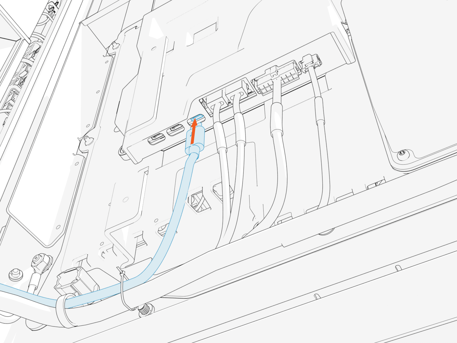
-
-
Zip tie the USB
Universal Serial Bus cable to the main cable harness.-
Ensure the door can open and close without pinching or pulling of any cables.
-
Ensure the USB
Universal Serial Bus cable does not touch the HV DC High Voltage Direct Current wires when the door is closed.

-
-
Pull the hardwire Ethernet cable (Cat6 STP
Shielded Twisted Pair) and cut to length for landing at the
Ethernet to USB Universal Serial Bus module. Allow for a service loop. and cut to length for landing at the ETH2USB module. Allow for a service loop.")
-
Field crimp an RJ45 connector onto the Ethernet cable. Use straight-through T568B pattern.
Do not ground the shield at this end of the Ethernet cable. Ground the shield at the end of the Ethernet cable that connects to the network server.
-
Test the Ethernet cable for functionality.
If using a Paige OSP Shielded GameChanger cable for a wire run length greater than 100 m (328 ft), follow the test procedure specified by Paige. See Paige GameChanger Resources.

-
Route the Ethernet cable through wireway clamps and connect it to the Ethernet to USB
Universal Serial Bus module. 
-
Route and connect the other end of the Ethernet cable to the network server.
Install Card Reader
If the site plan indicates the Power Link 2000 must be configured with a card reader, follow procedures below to install the Card Reader Kit.
-
Unpack the Card Reader Kit. Confirm all parts listed below are present.
For any missing component, contact chargepoint.com/support.

-
Replacement rear upper cover with pre-installed card reader
-
Long cable for connecting the card reader to product
-
-
Loosen screws (x6) to remove the existing rear upper cover of the Power Link 2000.
 to remove the existing rear upper cover of the Power Link 2000.")
-
Connect the USB
Universal Serial Bus-C end of the long cable to the Control and Communication Module (CCOM Control and Communications Module).-
Connection to 8-inch CCOM
Control and Communications Module
-
Connection to 15-inch CCOM
Control and Communications Module
-
-
Route the long cable's other connector to rear side through a hole at the back of the Power Link 2000 and insert the grommet into the hole.
Make sure to route and tie the long cable using cable ties to the main cable harness.
-
Bring the replacement upper rear cover (with card reader pre-installed) close to the rear of the Power Link 2000. Connect the card reader cable to the long cable.
 close to the rear of the Power Link 2000. Connect the card reader cable to the long cable.")
-
Align and seat the replacement rear cover onto the alignment pins (x2) on the frame of the Power Link 2000.
 on the frame of the Power Link 2000.")
-
Torque the screws to 4.5 Nm (40 in-lb).
.")
-
Check the removed cover for a label with serial number (SN). Request a replacement label for the new cover. Install the new label.
To request a new label with SN, contact chargepoint.com/support.. Request a replacement label for the new cover. Install the new label.")
Install Sequential Charging Kit
If the site plan indicates the Power Link 2000 must be configured for sequential charging, follow procedures below to install the Sequential Charging Kit.
-
Unpack the Sequential Charging Kit. Confirm all parts listed below are present.
For any missing component, contact chargepoint.com/support.

-
Bus bar bridges (x2)
-
M8 captive washer nuts (x4)
-
-
Install the bus bar bridges (x2). The bridges mount onto studs located on the HV DC
High Voltage Direct Current bus bars.. The bridges mount onto studs located on the HV DC bus bars.")
-
Fasten with concentric washer nuts (x4). Torque to 12.2 Nm (108 in-lb).
. Torque to")
Install Soft Shutdown Switch
If the site plan indicates the Power Link 2000 must be configured with a soft shutdown switch, follow procedures below to install the soft shutdown switch wires.
-
Pull the soft shutdown switch wiring through the conduit.

-
Loosen set screws (x2) at the soft shutdown terminal.
 at the soft shutdown terminal.")
-
Twist the soft shutdown switch wires together, using a minimum of five twists per foot.

-
Route the twisted wires through the wireway clamps (if necessary, use cable ties) towards the soft shutdown terminal. Cut the wires to length for landing at the terminal.
 towards the soft shutdown terminal. Cut the wires to length for landing at the terminal.")
-
Strip the wire ends.
.")
-
Insert the wires into the soft shutdown terminal. Torque set screws (x2) to 0.6 Nm (5.3 in-lb).
 to 0.6 Nm (5.3 in-lb).")
