Electrical Design
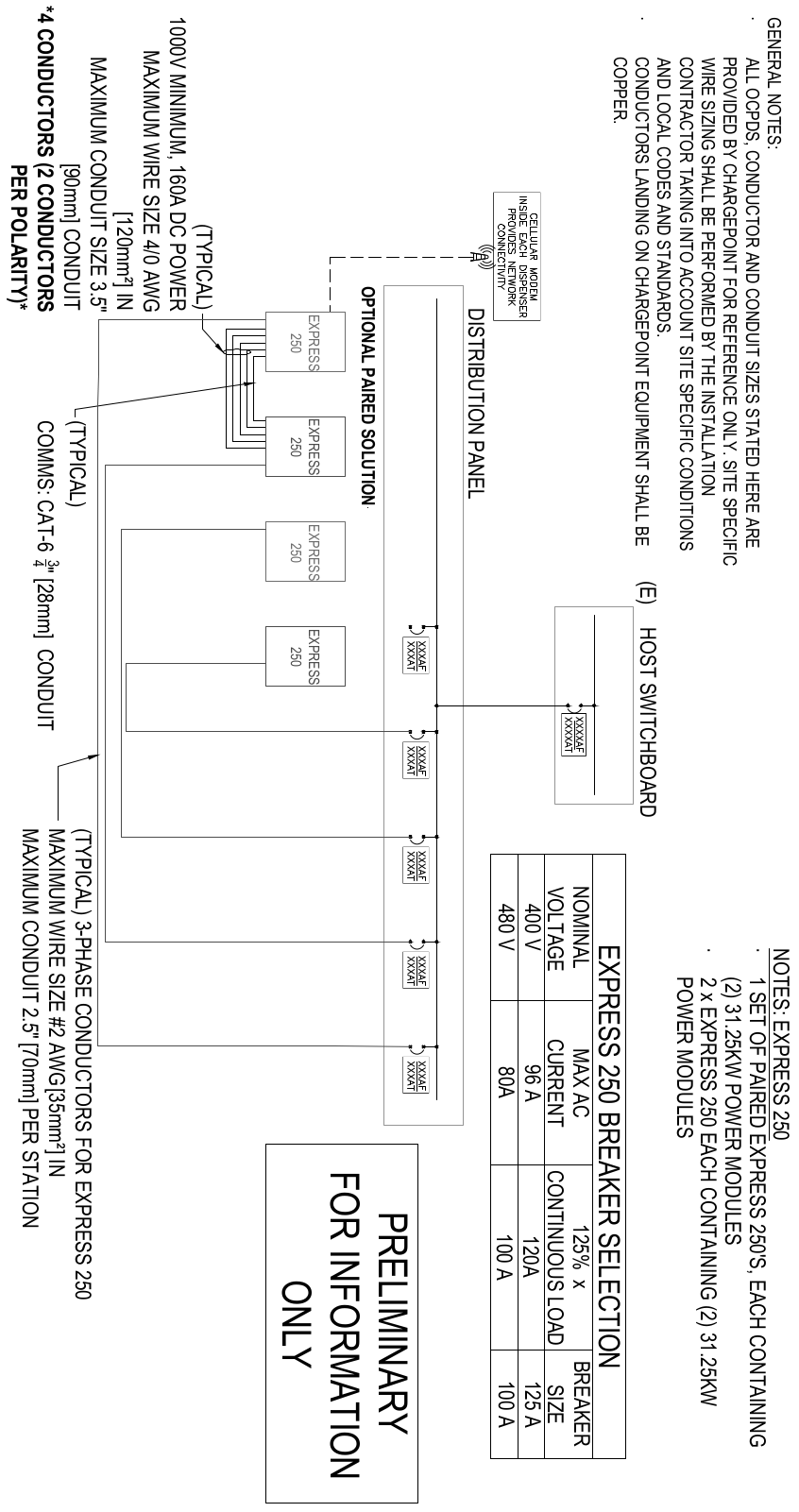
The Express 250 charging stations in North America are available with a maximum amperage of up to 80 A. The default installation requires service wiring to be installed underground. (If a site requires surface mounting, refer to Install the Surface Mount Plate for instructions on installing the station using a surface mount plate.) Conduit and wire size are determined based on the length of runs from the electrical panel to the station location. Service wiring must be run through conduit or ducting, or use armored cable, as required to comply with local electrical codes. Consult national and local codes or a project engineer to determine the grade, quality, and size of the conduit or cable. The ChargePoint Concrete Mounting Template (CMT) accommodates service wiring through the flare, conduit, or locally appropriate wiring method.
It is possible to pre-install charging stations as Standalone initially and pair them at a later date, if desired. In this case, install the DC and Ethernet conduit and run a pull rope through the conduit before landing the charging stations. Contact ChargePoint for instructions to pair two charging stations when ready.
Upstream Components
Charging stations are considered continuous load devices (EVs draw maximum load for long durations). Therefore, electrical branch circuits to EV![]() Electric Vehicle chargers must be sized at 125% of the load on each leg of a 3-phase panel for North America installations, in accordance with National Electric Code requirements. For other regions, refer to local code.
Electric Vehicle chargers must be sized at 125% of the load on each leg of a 3-phase panel for North America installations, in accordance with National Electric Code requirements. For other regions, refer to local code.
When planning multiple EV![]() Electric Vehicle charging stations, it is best practice to segment non-continuous and continuous loads, with all branch circuits for EV
Electric Vehicle charging stations, it is best practice to segment non-continuous and continuous loads, with all branch circuits for EV![]() Electric Vehicle charging on a dedicated electrical panel assembly with adequate circuit breakers. When sizing new electrical panels dedicated for EV
Electric Vehicle charging on a dedicated electrical panel assembly with adequate circuit breakers. When sizing new electrical panels dedicated for EV![]() Electric Vehicle charging, all branch circuits must support continuous load.
Electric Vehicle charging, all branch circuits must support continuous load.
Each charging station requires a service panel breaker as follows:
|
Nominal Voltage |
Max AC Current |
Maximum Circuit Breaker Size |
|---|---|---|
|
400 V AC (EU) |
96 A |
125 A |
|
480 V AC (NA) |
80 A |
100 A (125% continuous load required for N. America) |
The charging station does not contain an internal breaker. Therefore, its KAIC rating (KiloAmps Interrupt) is related to the station’s upstream breaker.
The charging station is tested to IEC 61000-4-5, Level 5 (6 kV @ 3000 A) standards. In geographic areas that experience frequent thunderstorms, supplemental surge protection must be installed at the service panel to guard against product damage.
Power Select Configuration and Circuit Protection
The Power Select feature allows installers and system designers to configure the charging station to operate at predefined power levels. This provides flexibility to align the station with available electrical service capacity, comply with applicable electrical codes, and optimize installation cost while maintaining safe and reliable operation.
Use Power Select to:
-
Match station output to site electrical limitations
-
Coordinate station load with conductor and overcurrent protection sizing
-
Support derating requirements for continuous operation and installation conditions
Supported Power Configurations
The following table shows the available Power Select options. Each option includes the required number of internal power modules, the station operating current and the recommended circuit breaker size.
|
Power Select (kW) |
Number of Power Modules |
Station Amperage (A) |
Circuit Breaker Size (A) |
|---|---|---|---|
|
62.5 |
2 |
80 |
100 |
|
50 |
2 |
64 |
80 |
| 30 | 1 | 40 | 50 |
ChargePoint recommends installing the station on a 100 A circuit breaker to support potential future increases in power output. This installation helps avoid additional infrastructure upgrades and recommissioning if higher Power Select outputs are needed later.
Station amperage values reflect nominal operating current at the selected power level. Circuit breaker sizes account for continuous-load requirements and standard breaker ratings. If Power Select is used, only one power module may be installed.
Installation and Code Compliance
All conductors, raceways and overcurrent protection devices must be sized according to the selected Power Select configuration and installed in accordance with applicable local, state and national electrical codes. Final conductor and breaker sizing must include all required derating factors, including continuous load operation, ambient temperature, conductor type and installation conditions.
Transformer Configuration
Refer to the following tables to configure electrical service.
|
|
North America |
Europe |
|---|---|---|
|
Input Rating |
480 V AC, 3-phase, up to 80 A, 60 Hz |
400 V AC, 3-phase, 96 A, 50 Hz |
|
Electrical Service Configuration |
277/480 4 wire WYE* |
230/400 Y, L1, L2, L3, N, Ground |
|
Product Connection |
3-phase 480 plus ground |
3-phase 400 plus protective earth |
*Delta (floating or grounded) is not supported
Neutral is not required for system operation, however Neutral-to-ground bonding is required at the Main Distribution Panel (MDP) supplying the charging station.
AC Disconnect Switch
A local AC disconnect switch, separate from the shunt trip wiring, is recommended to be installed between each charging station and the electrical panel. This is especially important if the main electrical panel or utility room is distant, out of line of sight, or has restricted access. For North America installations, refer to disconnect switch requirements per NEC![]() National Electric Code Article 625, “Electric Vehicle Charging and Supply Equipment Systems”.
National Electric Code Article 625, “Electric Vehicle Charging and Supply Equipment Systems”.
Do not install a DC disconnect between Paired charging stations.
RCD Use
The use of an RCD![]() Residual Current Device is not recommended. RCD
Residual Current Device is not recommended. RCD![]() Residual Current Device use can create nuisance tripping, especially during transient conditions such as power restoration, line surge, line dips, or phase loss.
Residual Current Device use can create nuisance tripping, especially during transient conditions such as power restoration, line surge, line dips, or phase loss.
To reduce the risk of shock, the charging station provides:
-
Galvanic (reinforced) isolation between the AC input and DC output. Current does not flow to earth ground, even in cases such as charge cable damage.
-
An output isolation monitor interrupter (IMI).
If the isolation level is compromised, charging is halted or prevented from starting, and the output de-energized. The isolation monitor operates continuously during charging to ensure the output is always galvanically isolated. UL 2231-1 requires that an isolation monitor interrupter (IMI) is provided in the product and evaluated during operation as part of certification testing.
Although RCD![]() Residual Current Device/GFCI
Residual Current Device/GFCI![]() Ground-Fault Circuit Interrupter use is required in mode 1,2,3 AC charger installations, neither UL nor IEC mandate an RCD
Ground-Fault Circuit Interrupter use is required in mode 1,2,3 AC charger installations, neither UL nor IEC mandate an RCD![]() Residual Current Device for a permanently installed mode 4 isolated output DC charger.
Residual Current Device for a permanently installed mode 4 isolated output DC charger.
RCD Settings
For Standalone installations where the use of an RCD![]() Residual Current Device (RCCB
Residual Current Device (RCCB![]() Residual Current Circuit Breaker or RCBO
Residual Current Circuit Breaker or RCBO![]() Residual Current Breaker with Overload Protection) cannot be avoided, use the following settings to minimize nuisance trips:
Residual Current Breaker with Overload Protection) cannot be avoided, use the following settings to minimize nuisance trips:
-
Type: A, F or B (type B and F preferred)
-
Trip threshold: 500 mA
-
Trip delay: 150 ms
If an RCD![]() Residual Current Device must be employed for a Paired installation, contact ChargePoint.
Residual Current Device must be employed for a Paired installation, contact ChargePoint.
Region Specific Notes: UK
When discussing DC charging station installations with a UK DNO (utility), include these two considerations:
-
Where possible, request TN-S
 Terra Neutral Separate earthing from the DNO (distribution network operator)
 -
The Express 250 represents a Class I construction, balanced 3-phase load greater than 500 W
Either statement allows UK DNOs to provide a PME earth terminal and avoids the requirement for a TT earthing arrangement and associated (300 mA) RCD![]() Residual Current Device. The second statement meets the clause in the IET Code of Practice for EV
Residual Current Device. The second statement meets the clause in the IET Code of Practice for EV![]() Electric Vehicle Charging Equipment Installation, 3rd Edition that allows the DNO to provide a PME connection for “on the street equipment”.
Electric Vehicle Charging Equipment Installation, 3rd Edition that allows the DNO to provide a PME connection for “on the street equipment”.
Installations at petrol stations are a special case that requires additional site planning. Contact Express 250 for more information.
Grounding/Earthing Requirements
-
The station must be connected to a grounded, metal, permanent wiring system.
-
North America: A grounded service neutral conductor must be run with circuit conductors and connected to an equipment-grounding terminal.
-
Europe: Use TN-S
Terra Neutral Separate or TN-C Terra Neutral Combined-S configurations. (TT is not recommended because it requires RCDs.) -
Ensure a grounding conductor that complies with local codes is properly grounded to earth at the service equipment or, when supplied by a separate system, at the supply transformer.
Shunt Trip Wiring
ChargePoint advises against installing an emergency stop (E-stop) button on charging stations. Drivers can unintentionally trip the emergency shutoff, causing inconvenience and downtime to site hosts. However, wiring to enable a remote shunt trip is standard on each station. This shunt trip wiring is activated when unsafe conditions are detected, such as a missing cover panel or a severe impact. All shunt trip behavior is already hard-coded into the charging station and has no programmable variables.
The charging station provides a set of unpowered (dry pair) contacts near the AC input terminals, to connect to a shunt trip device. These contacts are rated to 440 VAC and 5 ARMS.
When a shunt trip is used, select a breaker with a shunt trip that is within the contact rating of the Express 250 shunt trip contacts. Common ratings available for shunt trips are 12, 24, or 48 VDC, or 110-240, 400 VAC depending on the installation region. 480 VAC rated shunt trips may not be used.
Follow the installation guide provided by the breaker or shunt trip vendor. Control power is derived at the electrical panel.
-
Electrical panel
-
Express 250
-
Circuit breakers
-
Shunt trip
-
Control power (fused)
-
Shunt trip terminal block (near AC terminals)
Conduit
The outer diameter of conduit or armored cable must not exceed the sizes called out in the conduit layout drawing below. Conduit stub-ups cannot extend higher than 76.2 mm (3 in) above the surface of the concrete pad.
In regions that do not use conduit, armored cable may be laid in the same configuration to conform to the wire placement as shown in the chapter, Concrete Mounting Template. Ensure a length of at least 61 cm (2 ft) is left free above grade at each end to allow the wiring to reach the charging station AC terminals.

-
AC conduit: 50.8 mm (2 in trade size)
-
Shunt trip conduit: 19.1 mm (3/4 in trade size)
-
Anchor bolts
-
Paired installations only: Ethernet conduit: 19.1 mm (3/4 in trade size)
-
Paired installations only: DC conduit: 76.2 mm (3 in trade size)
-
Concrete surface
-
Concrete Mounting Template (embedded in concrete)
Depth of conduit or armored cable may vary by site. The image above does not dictate conduit depth, as long as the stub-ups are vertical and placed correctly.
Wiring Requirements for Standalone Stations
For full product specifications, refer to the Datasheet. Using that data, ensure that the installation location is equipped with service wiring that supports the station's power requirements:
-
Neutral conductor as required by region (a Neutral connection is not required for equipment operation and the terminal is provided for convenience only)
-
Shunt trip wiring: size 0.08 to 2.5 mm² (28 to 14 AWG
American Wire Gauge), fine stranded or solid -
AC conductors (L1, L2, L3) and ground per the following specifications:
|
Voltage Rating |
Temperature Rating |
Maximum Conductor Size for Terminals |
|---|---|---|
|
EU non-armored: 600/1000 V |
90 °C |
35 mm² |
|
EU armored: 600/1000 V |
90 °C |
35 mm² multi-core |
|
NA: 600 V |
90 °C |
Additional Wiring Requirements for Paired Stations
For stations that will be installed as Paired, follow all AC wiring requirements above as well as the following additional wiring.
-
Ethernet wiring for DC:
-
Minimum of CAT5e or better
-
Outdoor or plenum rated wiring
-
Maximum run length of 100 m (328 ft)
-
Leave 3.2 m (10.5 ft) of wire above grade at each end
-
Field crimp using straight-through pattern 568B
-
DC conductors (x4):
|
Voltage Rating |
Temperature Rating |
Maximum Conductor Size for Terminals |
Insulation Type |
DC Input/Output |
|---|---|---|---|---|
|
EU non-armored: 600/1000 V |
90 °C |
120 mm² |
XLPE |
160 A |
|
EU armored: 600/1000 V |
90 °C |
120 mm² 4-core and cable gland sized to local code (such as Cablecraft CCG-CW50 or similar) |
XLPE |
160 A |
|
NA: 1000 V |
90 °C |
XHHW-2 |
160 A |
-
2 positive and 2 negative conductors; 1 positive and 1 negative in each direction
-
USA/Canada: Copper only, maximum station DC output/input current: 160 A
-
EU/UK: Rated at 1000 V conductor to conductor (+/-500 V conductor to ground, LV
Low Voltage), copper only, maximum station DC output/input current: 160 A -
DC cable run must be continuous, with no joints or splices
-
Consult site drawings for site-specific conductor size and length (Appendix A provides conductor size calculation examples for reference)
-
Leave 61 cm (2 ft) of each conductor above grade at each end
-
DC lugs (x4):
-
Silver plated copper compression lug (2-hole specified for North America); tin plated is acceptable if used with dielectric grease
-
Holes for an M6 (1/4 in) stud at 19 mm (3/4 in) stud hole spacing
-
Maximum width 30 mm (1.18 in)
95 mm² (3/0 AWG American Wire Gauge) is sufficient for most sites unless ambient temperatures are >= 40 °C.
-
North America lug size: 3/0 or 4/0 AWG
American Wire Gauge -
Example UK/EU lugs for average conductor size are Weidmuller 1494410000 120 mm2 or similar (always review the lug manufacturer’s instructions for crimper tool and die compatibility)
-
Contact ChargePoint if the installer requires lugs for 3/0 (kit 99-002644) or 4/0 (kit 99- 002645) conductors
When DC conductors are pulled through conduit, label each end of each DC conductor to aid installation as follows:
-
Station 1 A+ on one end and Station 2 B1+ on the other end
-
Station 1 A- on one end and Station 2 B1- on the other end
-
Station 1 B1+ on one end and Station 2 A+ on the other end
-
Station 1 B1- on one end and Station 2 A- on the other end
 Be sure to connect positive to positive, and negative to negative, on the same wire. Do not reverse the polarity.
Wiring Diagram