Install the Surface Mount Plate
This chapter describes how to install a surface mount plate that allows an Express 250 DC fast charging station to be anchored without pouring new concrete. The surface mount plate is used with drilled and epoxied anchor bolts. When surface mounting an Express 250, there are two options for wiring:
-
Reusing an existing AC underground conduit (possibly pulling new conductors)
-
Using a Surface Conduit Entry (SCE
 Surface Conduit Entry) kit that provides a rear conduit entry box for conductors to enter the station through surface wireways
Installing the Express 250 using the surface mount plate requires one ChargePoint Certified Installer and about 2 to 2.5 hours to complete (not including epoxy cure time). This time estimate includes the full charging station installation, including the applicable steps described in the
Shunt trip wiring is normally a feature of the Express 250, but is not required for operation. If shunt trip wiring will be used, run a conduit or wireway for the low voltage shunt trip wires that is separate from the AC conductor conduit or wireway.
Before You Begin
Before performing any procedure, the technician must disconnect the power to the charging station at the service panel. Follow local code to de-energize the applicable circuit and lockout/tagout the upstream breaker before proceeding. Use a multimeter and check that the power is off. Keep power off for the circuit until all cover panels are correctly reinstalled and the work is complete.
FAILURE TO FOLLOW THESE INSTRUCTIONS CAN RESULT IN SERIOUS INJURY, LOSS OF LIFE, OR PROPERTY DAMAGE.
- If the charging station is not installed, commissioned, or serviced by a ChargePoint certified technician using a ChargePoint-approved method, it is excluded from all ChargePoint and other warranties and ChargePoint is not responsible.
- You must be a licensed electrician and complete training at https://www.chargepoint.com/partners/training-certification to become ChargePoint certified and to access ChargePoint's web-based installer tools or ChargePoint Installer app.
- Do not use power tools during installation or servicing. Over-torquing can damage the equipment.
- Do not install the charging station in inclement weather. If you must complete the installation in rain or wind, you must use a weather-proof shelter that covers all boxes and components.
Required Tools and Materials
For a surface mount plate installation, the installer must bring:
-
All tools and materials mentioned in the
-
Concrete drill, level feature recommended
-
25 mm (1 in) and 6 mm (1/4 in) concrete bits
-
25 mm (1 in) rebar bit if needed
-
24 mm (15/16 in) open ended wrench
-
Flathead screwdriver
-
750 ml of epoxy with bonding strength of 11.7 MPa minimum, compressive strength of 82.7 MPa minimum, and tensile strength of 49.3 MPa minimum, such as Hilti HIT-RE 500 V3 (normal cure time), Hilti HY-200 (fast curing), or similar
Different epoxy types have different cure times at various temperatures. Check local temperatures for the site in advance to help choose an appropriate epoxy. -
Vacuum and/or brush
-
Marker
-
Isopropyl wipes
-
Paper towels
-
Read the
- If the Express 250 will be paired, check the serial number on the rear surface just under the cable swing arms. For North America stations with SNs prior to 1929xxxx, or EU/UK SNs prior to 2003xxxx, the station also requires a Pairing Upgrade Kit. Contact ChargePoint for the kit and the installation guide for that configuration.
Check Site Readiness
Before beginning work, check that the site meets the basic requirements outlined below, as illustrated in the following image. Measurements are listed in mm (in).
-
The panel breaker serving the charging station matches the site drawing requirements depending on local code and the type of installation: 62.5 kW Standalone, 125 kW Paired, or 50 kW de-rated (when replacing a previous, lower-amperage system).
-
The smooth, level concrete pad has been approved by a structural engineer for the Express 250 dimensions and weight, or the pad conforms to these general specifications:
-
At least 305 mm (12 in) deep (or deep enough to be 305 mm (12 in) below the frost line)
-
At least 1296 mm (51 in) on each side
-
Contains #4 rebar top and bottom 305 mm (12 in) on center
-
Concrete 2500 PSI minimum
These pad specifications are applicable in most conditions, as described in this document. In some extreme conditions, a larger pad would be required. -
-
Charging station sites are positioned so that each station is centered on a parking space (unless curbside), with the front of the station facing the vehicle. (This maximizes cable reach.)
-
The cellular signal strength at the station location has been tested and is consistently strong. If RSRQ is measured at -10 dB or better, then RSRP can be -90 dBm or better. If RSRQ cannot be measured or is not adequate, RSRP must be -85 dBm or better.
-
The service clearance of open space (not necessarily at system grade) extends a minimum of 683 mm (26.9 in) beyond the station in front, 396 mm (15.6 in) beyond the station in back, and 788 mm (31 in) beyond the station on each side (image callout (a)).
If the Express 250 will use a SCE Surface Conduit Entry kit, check the -
The front of the station has 352 mm (14 in) of space at grade from the front right anchor, extending 1700 mm (67 in) to the left without any permanent obstructions (bollards, wheel stops, etc), refer (b).

If the site does not meet these basic requirements, contact ChargePoint before continuing.
Check the Surface Mount Plate Kit Contents

Check the contents of the Surface Mount Plate Kit before beginning work. The kit includes:
-
Surface mount plate
-
M16X300 anchor bolts, washers, and nuts (x4)
-
Anchor bolt plastic caps (x4)
Prepare the Express 250
Prepare the station and power modules, then follow the installation guide for setup.
-
Receive the Express 250 station and its Power Modules at the site.
-
Follow the directions in section 1 of the Express 250 Installation Guide to familiarize yourself with the process, crate contents, and required tools and materials.
Install Surface Mount Anchor Bolts
To install the surface mount anchor bolts, perform the following steps:
-
Place the surface mount plate at the proposed location. Align the large left hole with AC conduit if present (for example, when replacing an older station). Check that the station placement on the pad meets the site requirements.
Ensure the rear clearance leaves room for surface conduit runs if present, and for service clearance.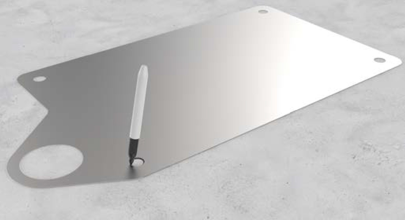
-
Use a marker to mark the locations for the Express 250 anchor bolts. Remove the surface mount plate.
-
Use the 6 mm (1/4 in) concrete drill bit to drill each pilot hole about 51 mm (2 in) deep. The holes must be parallel to each other and perpendicular to grade.

-
Use a vacuum or brush to clean the dust from the holes.
-
Use the 25 mm (1 in) concrete drill bit to drill each anchor hole a minimum of 229 mm (9 in) deep. Anchor bolts must have 127 mm +/- 12.7 mm (5 in +/- 1/2 in) above grade.
-
Place the surface mount plate on the ground again. Verify that the new holes for the Express 250 align with the holes in the surface mount plate.
-
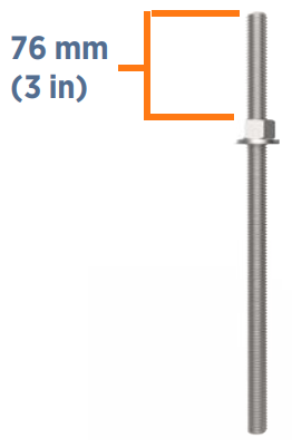
Thread a washer and a nut onto each anchor bolt, so that the measurement from the top of the nut to the top of the bolt is 76 mm (3 in).
-
Put a piece of tape above each nut to prevent it from floating upward when rotating the bolt into the epoxy later.
-
Prepare the epoxy. Ensure the applicator is dispensing correctly mixed epoxy before beginning work (for example, the Hilti epoxy is white when unmixed and grey when mixed).
-
Fill the first anchor bolt hole with epoxy until the epoxy is about 44.5 mm (1.75 in) from the top of the hole.
Continue immediately to the next step because the epoxy sets within about eight minutes.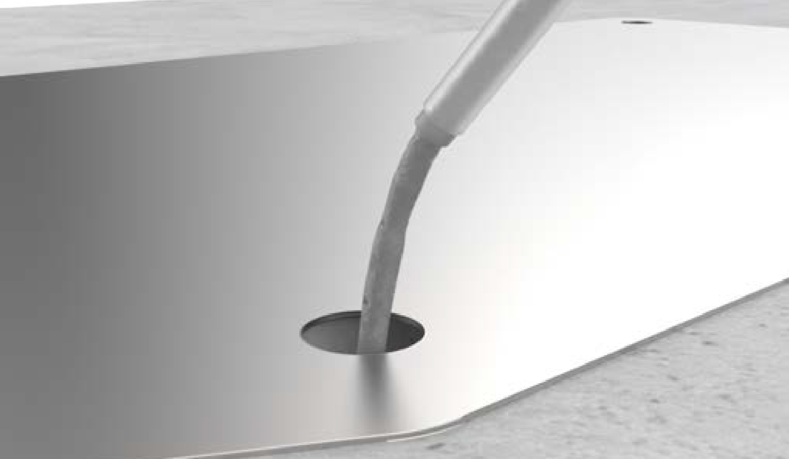
-
Insert the mounting bolt into the hole. Rotate the mounting bolt as you insert it to draw epoxy into the threads. Lift the anchor bolt again to see how close to the surface the epoxy has filled. If the epoxy is below grade level, add enough to fill the hole to grade level. Use paper towels to wipe up any excess.

-
Measure the nut distance from the top of each bolt again and adjust if needed. These nuts help secure the surface mounting plate to the concrete and should be flush against the base when installed.
-
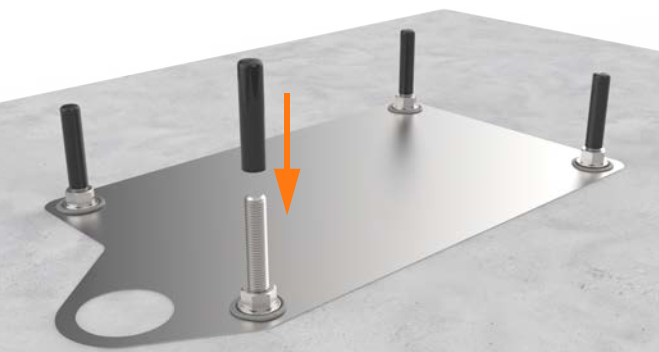
If the Express 250 station will not be immediately installed, insert a protective plastic cap over the bolt.
-
Use a level to check that each anchor bolt is plumb. If needed, adjust while the epoxy is still setting.
-
Repeat the above epoxy steps for each of the other three anchor bolts.
Stop and allow the epoxy to cure for the initial cure time listed on the epoxy, before beginning to install the Express 250.
Anchor and Label the Express 250 Station
To anchor and label the Express 250 Station, perform the following steps:
-
Check that the epoxy has set completely.
-
Torque all four nuts to 94.9 Nm (70 ft-lb).
-
Follow the instructions in the
The station should rest on the leveling nuts, not on the surface mount plate. -
Stop before the section "Connect the AC wiring".
-
If required, adjust the ratings with a new label over the existing ratings line, just below the swing arms in the back:

-
If the Express 250 is being connected to wiring and a breaker of 80 A, affix the 50 kW ratings label to the station
-
If the Express 250 is being paired, affix the 125 kW label to the station
-
-
Continue normal installation of the Express 250 charging station per the
-
Complete normal Express 250 installation and testing per the
