Install the CMK
To install the CMK![]() Cable Management Kit, perform the following steps:
Cable Management Kit, perform the following steps:
Check the Box Contents
Before unpacking any shipping boxes, place a floor mat, padded ground covering, or similar material in an area close to the installation site. When unpacking shipping boxes, place all components on the ground covering and ensure that all components are present and undamaged. Unpack shipping boxes only when you need to, as described in this Installation Guide.
Locate Box #1, the CP4300 Charging Station and find the bag containing the mounting fasteners (screws and plastic wall anchors).
Open Box #2, the Wall Mount Kit and ensure you have all the components listed below (graphics are not to scale).
Locate Box #4, the Cable Management Kit (CMK![]() Cable Management Kit). Do not open the box until later in this section.
Cable Management Kit). Do not open the box until later in this section.
|
Cable cover clamp (1) |
|
|
Cable cover base (1) |
|
|
Cable Management Kit (CMK |
|
|
CMK |
|
|
CMK |
|
|
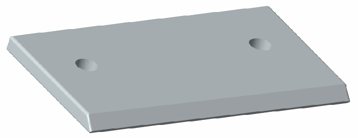
Support bracket cleat (1) |
|
|
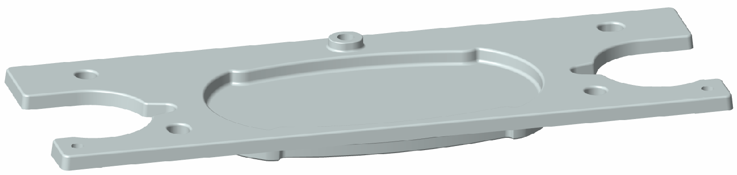
Support bracket hanger (1) |
|
|
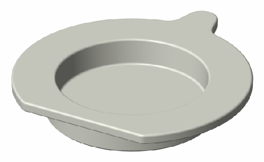
Pedestal hole plate (1) |
|
|
Strain relief hole plug (2) |
|
|
Installation kit (1) |
Includes:
|
|
Grounding kit (1) |
Includes:
|


Install the Grounding Components (UK Only)
To install this charging station in the United Kingdom, begin by installing the grounding components.
-
Install a cable gland onto each power cable.
-
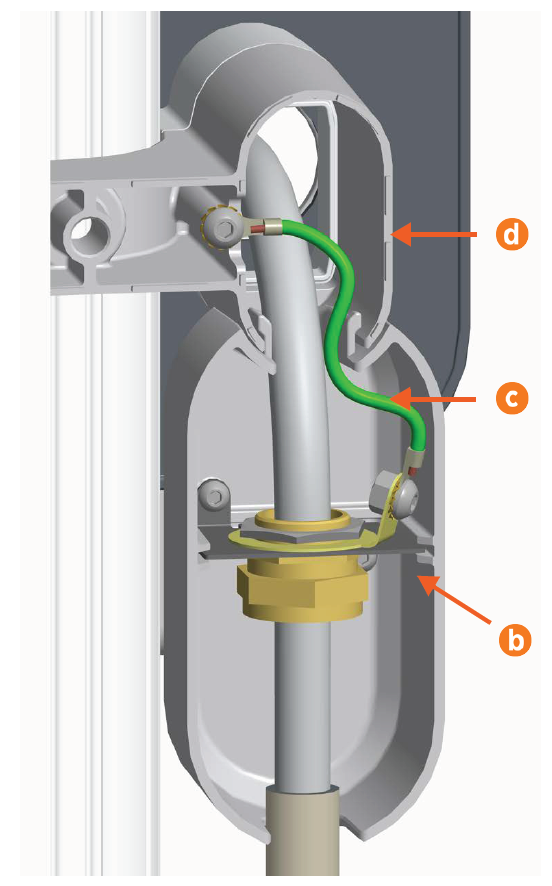
Use a 10 mm M8 button head hex screw, an M8 toothed washer, and a lock nut to connect the included grounding cable to each cable gland (a).

-
Using the included fasteners, connect each gland to one of the metal plates.
-
Slide each plate into a junction box.
-
Slide each junction box into the back of the cable cover base, one on each side.
-
Use a 10 mm M8 button head hex screw and an M8 toothed washer to connect each grounding cable (c) to the back of the cable cover base (d).
Install the Cable Cover Base
-
Measure and mark a spot on the wall 106 cm from the ground and aligned with the power cables.
-
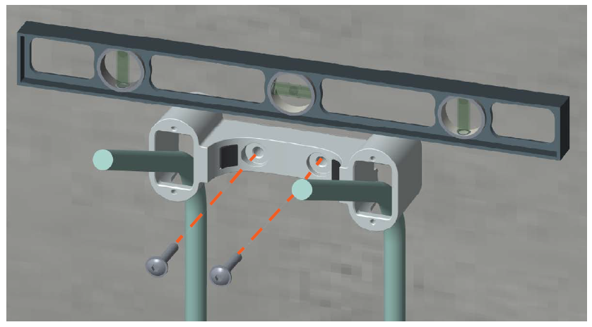
Align the top of the cable cover base with the mark on the wall. Use a spirit level to ensure the base is perfectly level.
-
Using the base as a template, mark where to drill holes for the mounting screws.
-
Using a 10 mm masonry drill bit, drill the holes.
-
Optional: If required at the installation site, gently tap the included wall anchors into the holes.
If you are installing the charging station within the United Kingdom, complete the steps described in Install the Grounding Components (UK Only) before continuing. -
Guide the power cables through the holes in the cable cover base, then bend them forward 90 degrees.
-
Use two 58 mm M8 self-tapping Torx screws to secure the base to the wall. Lightly tighten the screws.
-
Use a spirit level to ensure that the base is perfectly level on the wall. Torque the screws to 16 Nm.
Prepare the Cable Cover Clamp
-
Using a 5 mm hex driver and a 10 mm M8 button head hex screw with an M8 toothed washer, connect the 406 mm grounding cable to the cable cover clamp. Torque the screw to 16 Nm.

-
Put the cable cover clamp carefully to one side to install later in this section.
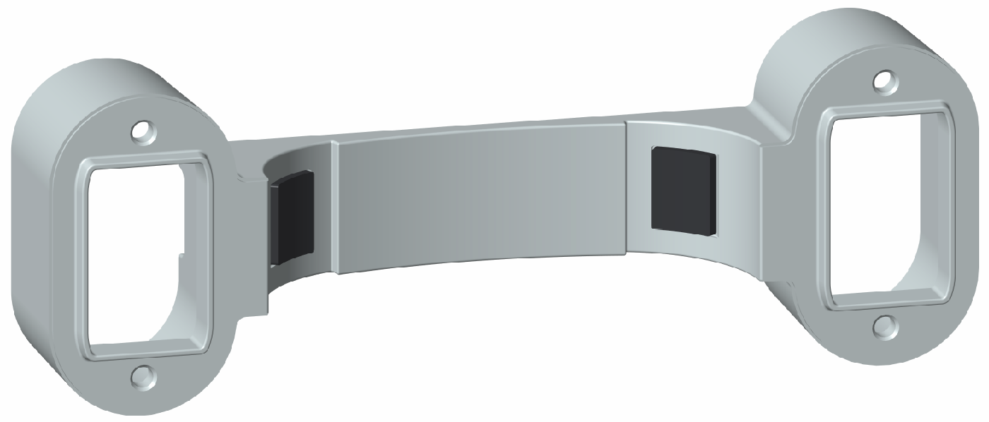
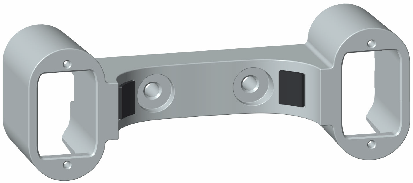
Mount the CMK Clamp to the Wall
The CMK![]() Cable Management Kit clamp comes in four pieces (shown in Check the Box Contents):
Cable Management Kit clamp comes in four pieces (shown in Check the Box Contents):
-
1 clamp spacer
-
1 clamp base (attaches to the spacer)
-
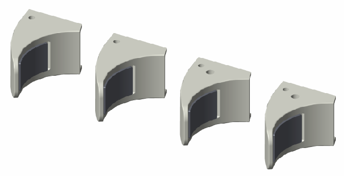
2 clamp ends (attach to the base)
-
Measure and mark a spot on the wall that is 40 cm from the ground and centered under the cable cover base that you just installed.
Once installed, the CMK
 Cable Management Kit clamp must be centered under the cable cover base (a).
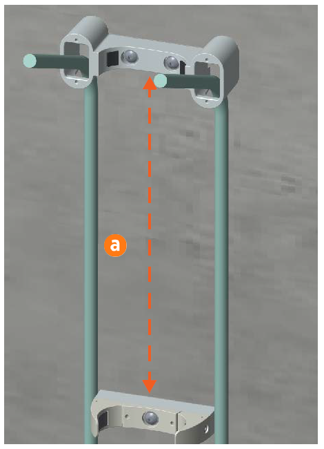
-
Align the top of the clamp spacer with the mark on the wall. Use a spirit level to ensure that the clamp spacer is centered under the power cable cover base.
-
Using the clamp spacer as a template, mark where to drill the hole for the mounting screw.
-
Using a 10 mm drill bit, drill the hole.
-
(Optional) If required at the installation site, gently tap a wall anchor into the hole.
-
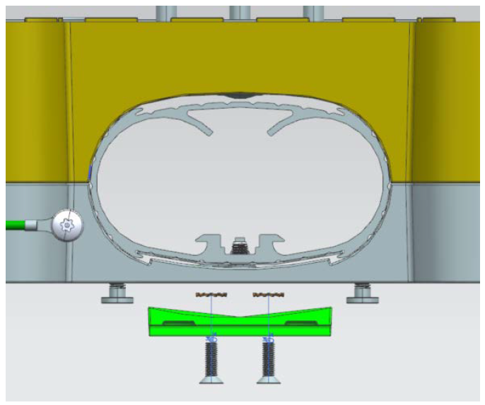
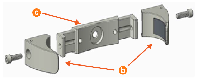
Using a 6 mm hex driver and two 25 mm M8 socket head cap screws, attach the clamp ends (b) to the sides of the clamp base (c). Hand- tighten the screws. Do not fully tighten the screws yet.
-
Orient the spacer so that the hole on one long side faces down. Fit the clamp base and spacer together (d) and align them with the drilled hole.
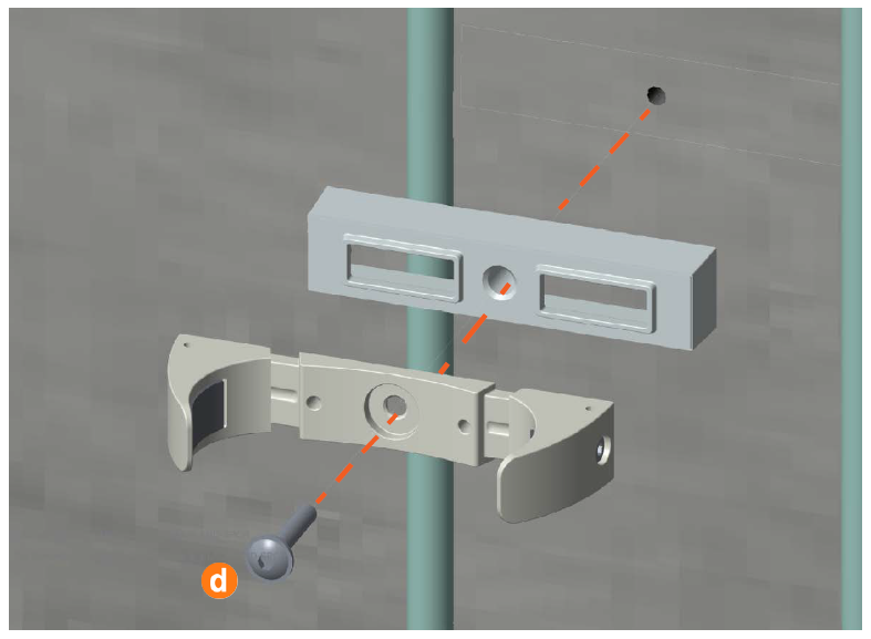 Ensure the hole on the spacer is facing down, not up, or you cannot install the grounding wire in a later step.
 -
Use a 58 mm M8 pan head Torx screw to secure the clamp base and spacer to the wall. Hand- tighten the screw.
-
Use a spirit level to ensure that the components are perfectly level on the wall. Torque the screw to 16 Nm.
Prepare the CMK
Locate Box #4, the Cable Management Kit (CMK![]() Cable Management Kit).
Cable Management Kit).
-
Remove the CMK
Cable Management Kit from the box and place it carefully on a padded ground covering with its base (a) close to the installation site.Do not unwrap the ropes. -
Remove and discard the two 10 mm drive shipping screws (b) from the front face of the CMK
Cable Management Kit.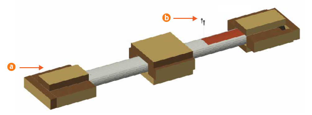 When you remove the shipping screws, the counterweights are free to move in either direction. To prevent damage or injury, always carry the assembly with the top end higher than the bottom end.
 -
Remove the packaging.
-
Carefully roll the CMK
Cable Management Kit onto its front side with the sign face down. -
Using a 5 mm hex driver, a 10 mm M8 button head cap screw, and an M8 toothed washer, connect the 127 mm grounding cable to the CMK
Cable Management Kit. Torque the screw to 16 Nm.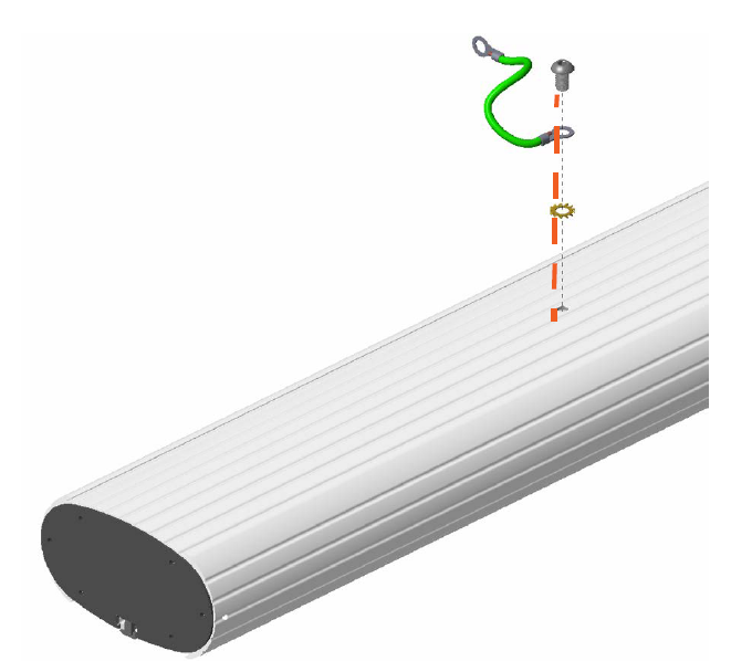
Install the CMK
-
Carefully lift the CMK
Cable Management Kit to a vertical position, top up, then place it on the ground so that it fits into the power cable cover base and CMK Cable Management Kit clamp.Continue to support the CMK Cable Management Kit until it is fully secured in place.

-
Tighten the screws on both CMK
Cable Management Kit clamp ends. Alternate tightening the left side and the right side of the CMK Cable Management Kit clamp until it fits evenly and securely around the CMK Cable Management Kit.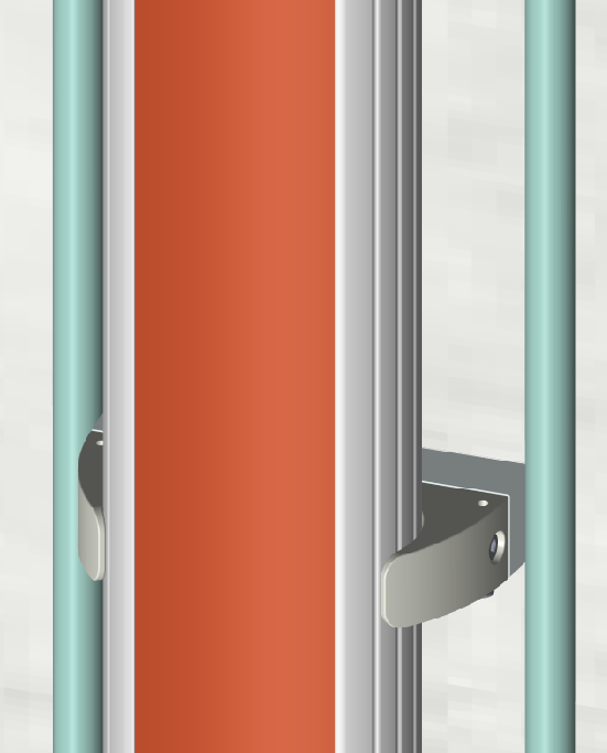
-
Place the cable cover clamp over the CMK
Cable Management Kit, aligning it to the cable cover base. -
Use a 6 mm hex driver and four 20 mm M6 button head cap screws to secure it in place. Torque the screws to 6.5 Nm.
It is now safe to let go of the CMK
Cable Management Kit.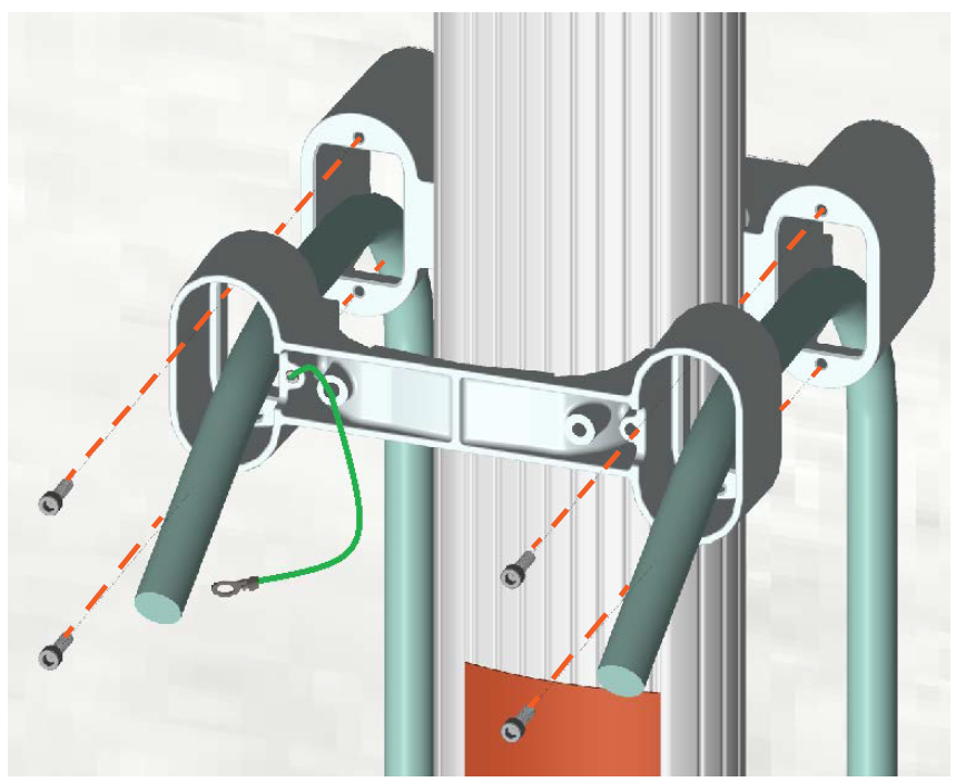
-
Using a 5 mm hex driver, a 10 mm M8 button head cap screw, and an M8 toothed washer, connect the loose end of the grounding cable from the CMK
Cable Management Kit to the hole on the bottom of the CMK Cable Management Kit clamp spacer, as shown below. Torque the screw to 16 Nm.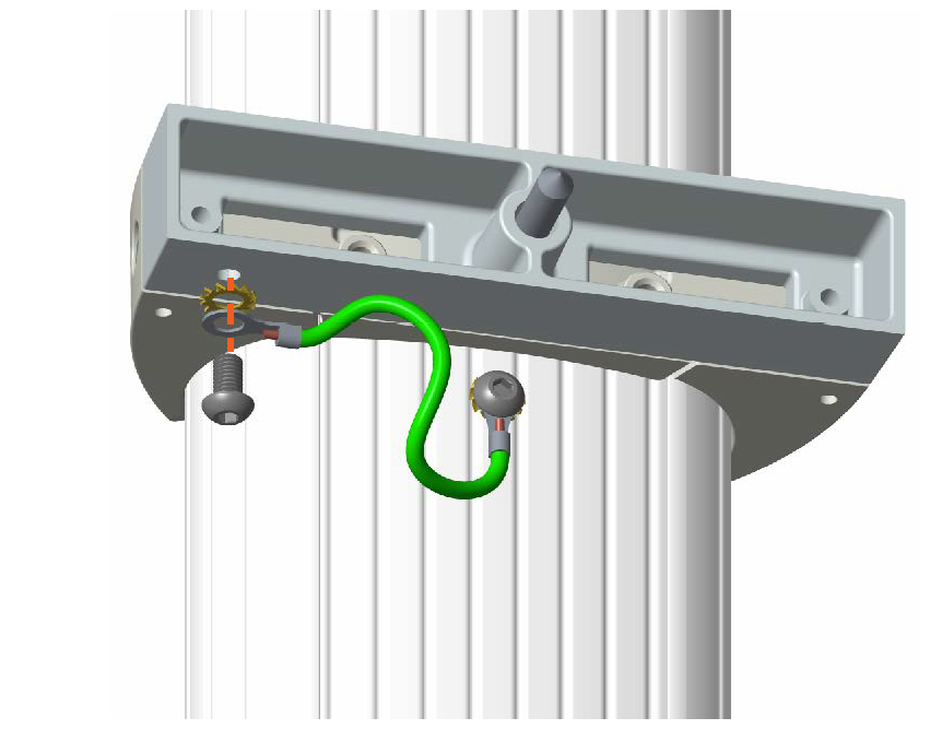
-
Use a spirit level to ensure that the CMK
Cable Management Kit is completely perpendicular. Check both the side and the front of the CMK Cable Management Kit. -
Make any required adjustments before continuing to the next step.
Install the Support Bracket Hanger
-
Using two 14 mm M8 flathead Torx screws and two M8 star washers, secure the hanger onto the CMK
Cable Management Kit using the predrilled holes. Torque the screws to 16 Nm.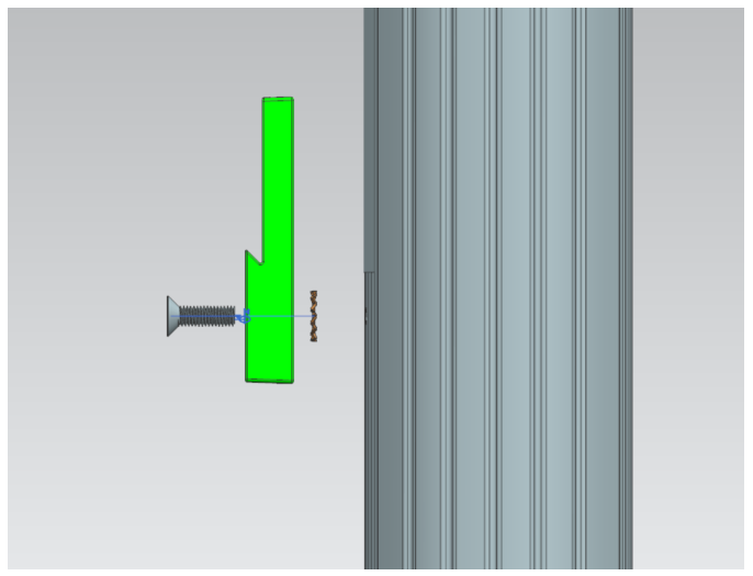
-
Place the remaining components from Box #2, the Wall Mount Kit, in a safe place for later use.