Install the Station Mounting Bracket
To install the station mounting bracket, perform the following steps:
Check the Box Contents
Before unpacking any shipping boxes, place a floor mat, padded ground covering, or similar material in an area close to the installation site. When unpacking shipping boxes, place all components on the ground covering and ensure that all components are present and undamaged. Unpack shipping boxes only when you need to, as described in this Installation Guide.
Open Box #3, the Station Mount Kit and ensure you have all the components listed below (graphics are not to scale). You also need the remaining components from Box #2, the Wall Mount Kit.
|
Support bracket (1) |
|
|
Fascia (1) |
|
|
Trim wall (1) |
|
|
Installation kit (1) |
Includes:
|


Build the Station Mounting Bracket
-
Find the pedestal hole plate and the remaining grounding cable from Box #2, the Wall Mount Kit.
-
Using a 5 mm hex driver, a 10 mm M8 button head cap screw, and an M8 toothed washer, connect the 635 mm grounding cable to the pedestal hole plate. Torque the screw to 16 Nm.
Place the pedestal hole plate aside to install in a later step.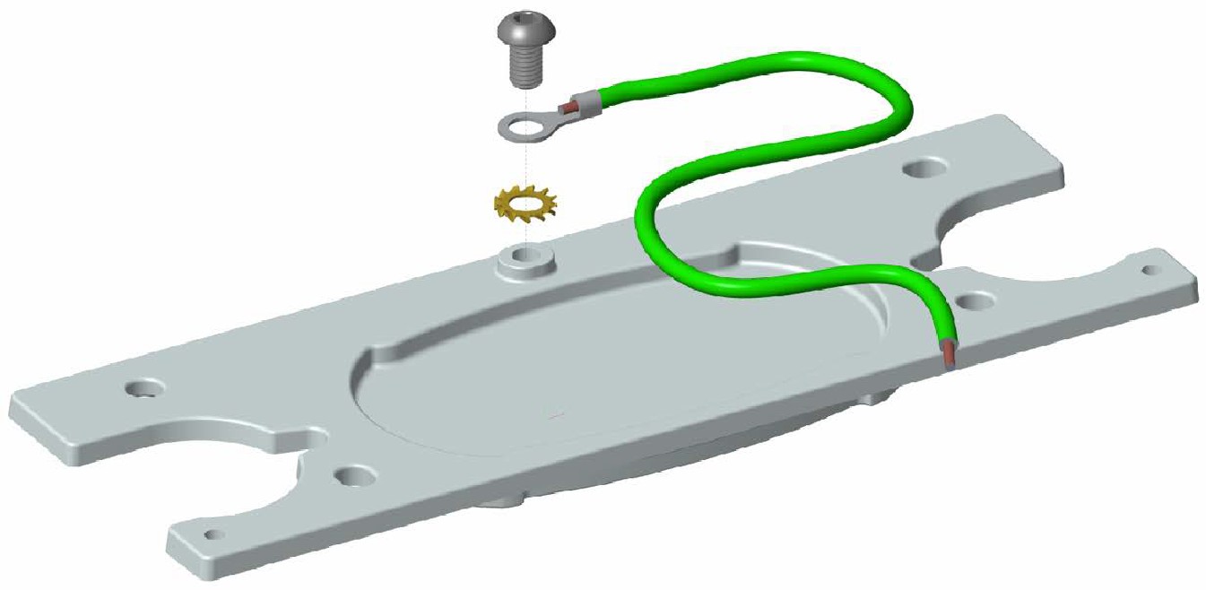
-
Fit the support bracket into the fascia.

-
Find the support bracket cleat in Box #2. Note that the cleat has one angled edge (a).
-
Place the cleat on the reverse side of the fascia (b), angled edge towards the base of the support bracket (c). Position the bare metal side of the cleat away from the bracket.
Ensure that the cleat is aligned properly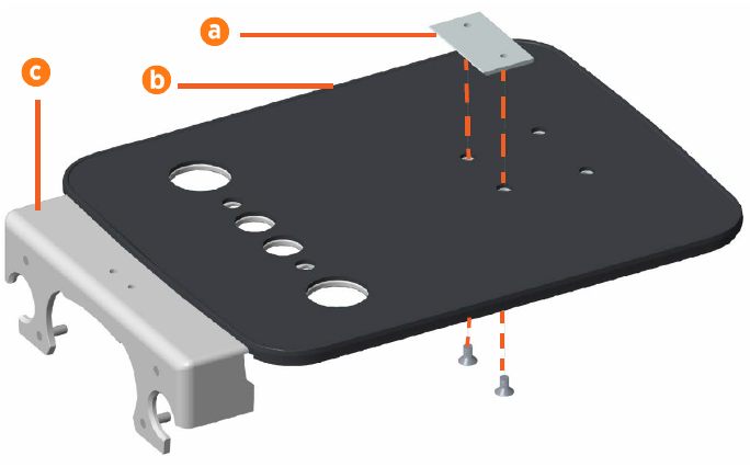
-
Use a 5 mm hex driver and two 14 mm M8 flat head socket screws to secure the support bracket, fascia, and cleat together. Torque the screws to 6.5 Nm.
-
The second CMK
 Cable Management Kit clamp (included in Box #2) comes in three pieces (no spacer required):
-
1 clamp base
-
2 clamp ends
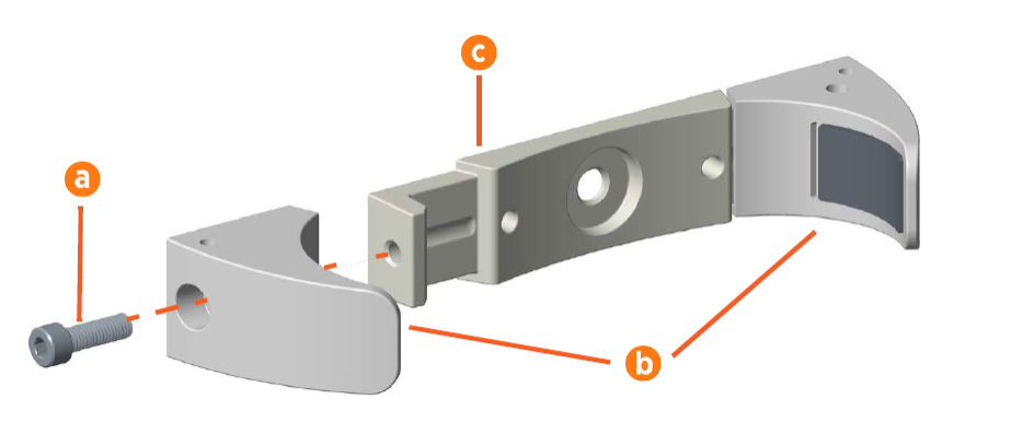
Using a 6 mm hex driver and two 25 mm M8 socket head cap screws (a), attach the clamp ends (b) to the sides of the clamp base (c). Install the two clamp ends with drilled holes on the right side of the grounding plate as you face the back of the plate with the holes facing up (d). Hand-tighten the screws. Do not fully tighten the screws yet.
-
-
Align the CMK
Cable Management Kit clamp on the reverse side of the fascia. Use a 5 mm hex driver and two 20 mm M8 flat head socket screws to secure the clamp base in place.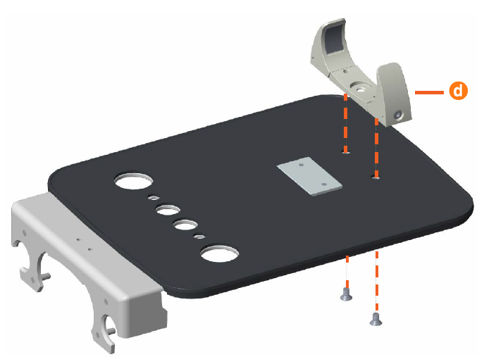
-
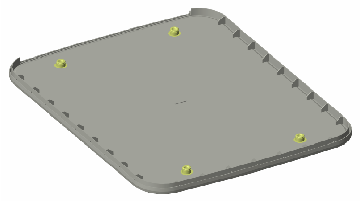
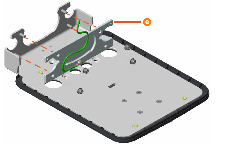
Position the pedestal hole plate (e) over the four bolts at the bottom of the support bracket, then use four M8 locknuts to secure it in place. Torque the bolts to 16 Nm.
-
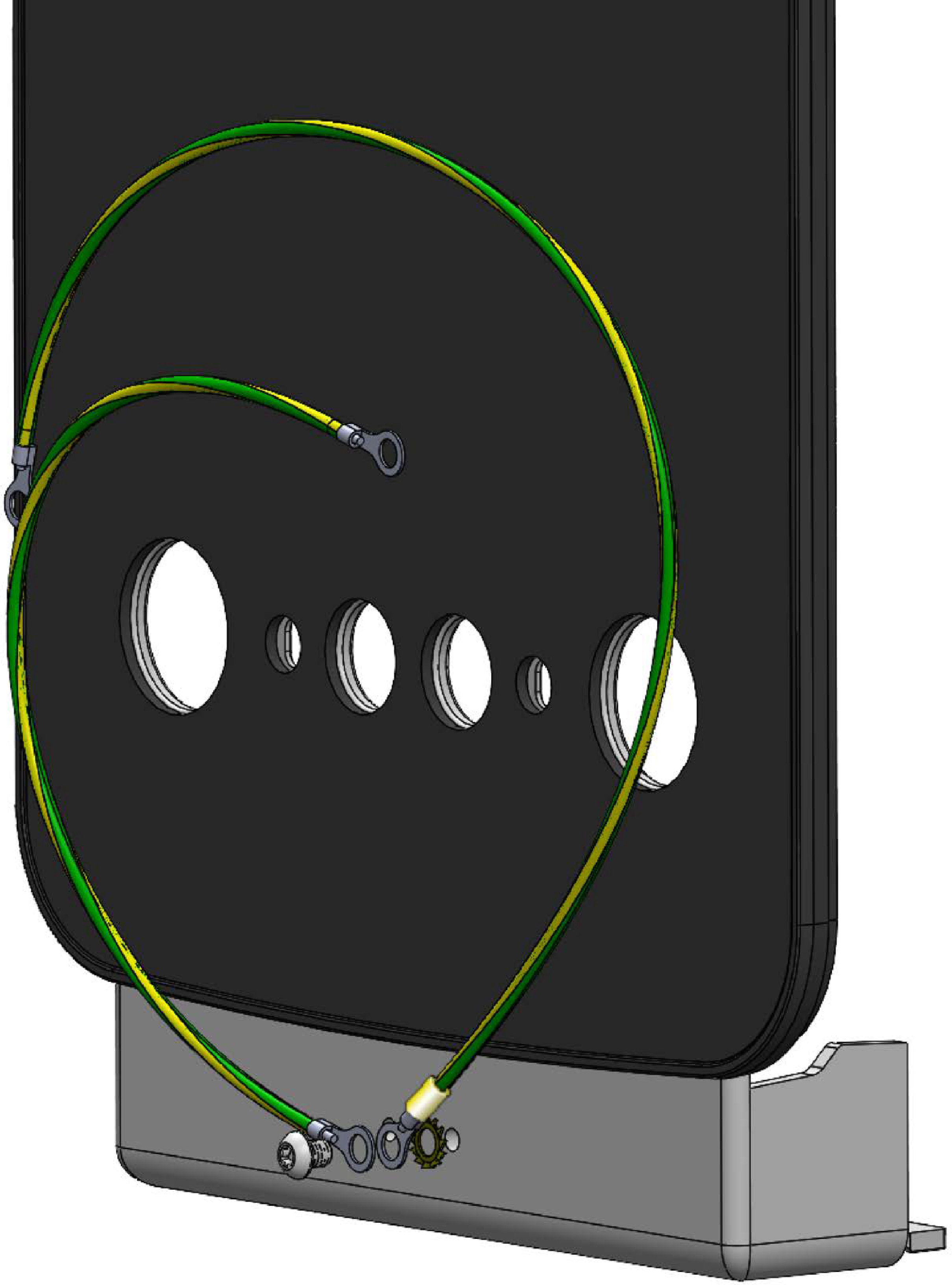
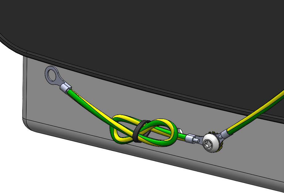
Using a 5 mm hex driver, a 10 mm M8 screw, and a star washer, connect one end of the 635 mm grounding cable and one end of the 241 mm grounding cable to the left M8 hole in the station mounting bracket.
-
Use a cable tie to make sure the excess length of 241 cable is tied in loops leaving approximately 25 mm free.
Install the Station Mounting Bracket
-
Using wire strippers, strip the outer jacket of the power cables back to the front edge of the power cable bracket.
-
Wrap electrical tape around the end of each cable, to make it easier to feed the cables into the station mounting plate.
-
Hold the station mounting bracket in front of the CMK
Cable Management Kit and feed the power cables through the two large openings in the bracket. -
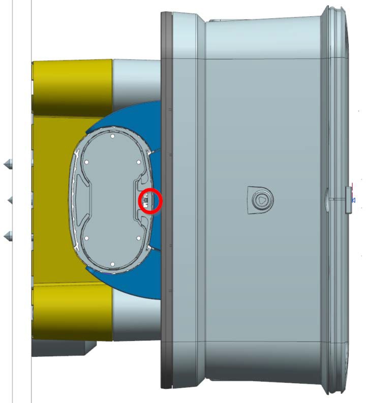
Guide the station mounting bracket so that the cleat (a) on the back seats securely onto the hanger on the CMK
Cable Management Kit (b). -
Using a 6 mm hex driver and two 16 mm M8 socket head cap screws (c), secure the station mounting bracket to the CMK
Cable Management Kit.
-
Route the 635 mm grounding cable through the gap between the CMK
Cable Management Kit column and the CMK Cable Management Kit Clamp end.Make sure the lower portion of the CMK Cable Management Kit column is secure. This ensures there is a gap between the back of the CMK Cable Management Kit column and the CMK Cable Management Kit Clamp for the grounding cable.
-
Using a 5 mm hex driver, a 10 mm M8 screw, and a star washer, connect the 635 mm grounding cable to the CMK
Cable Management Kit Clamp end (a).Use a cable tie to make sure that any excess length of the cable is tied up in loops so that the cable is taut and not visible when looking at the front of the station.
-
Using a 5 mm hex driver, a 10 mm M8 screw, and a star washer, connect the loose end of the 241 mm grounding cable to the front of the CMK
Cable Management Kit column (a). Torque the screw to 16 Nm.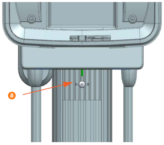
-
Use the cable tie provided to make sure that any excess length of the cable is tied up in loops so that the cable is taut and not visible when looking at the front of the station.
-
Tighten the screws on both CMK
Cable Management Kit clamp ends. Alternate tightening the left side and the right side of the CMK Cable Management Kit clamp until it fits evenly and securely around the CMK Cable Management Kit.
