Wire the Charging Station
Review the wiring diagram appropriate to the station configuration being installed and complete the recommended configuration.
Wiring Options
In three phase installations, consider the total quantity of charging stations to be installed at the site. To better balance load across all three phases across the site, ChargePoint provides labels to rotate incoming power across the terminal block.

For each charging station, follow the directions according to the configuration options shown:
-
Single port charging station, review the Standard Wiring, Single Port Station. Then proceed to Complete a Standard Wiring Configuration.
-
Dual port stations with two input power cables, review the Standard Wiring, Dual Port Station. Then proceed to Complete a Standard Wiring Configuration.
-
Dual port stations sharing one power cable, review the Circuit- Sharing Wiring (Dual Port Station Only). Then proceed to Complete a Circuit-Sharing Configuration (Dual Port Stations Only). Install the ChargePoint Power Management Jumper to power both ports from a single circuit. The L1 to L1 jumper is included. For phase shifting between charge ports in the station, use the L1 to L2 jumper, sold separately.
Wiring Diagrams
|
Output |
Input Circuits |
Panel Breaker Required |
Breakers Required |
|---|---|---|---|
|
Single Port Stations |
|||
|
22 kW |
1 |
3-phase 32 A x 1 |
1 |
|
11 kW |
1 |
3-phase 16 A x 1 |
1 |
|
7.4 kW |
1 |
1-phase 32 A x 1 |
1 |
|
3.7 kW |
1 |
1-phase 16 A x 1 |
1 |
|
Dual Port Stations |
|||
|
22 kW |
2 |
3-phase 32 A x 2 |
2 |
|
11 kW |
2 |
3-phase 16 A x 2 |
2 |
|
7.4 kW |
2 |
1-phase 32 A x 2 |
2 |
|
3.7 kW |
2 |
1-phase 16 A x 2 |
2 |
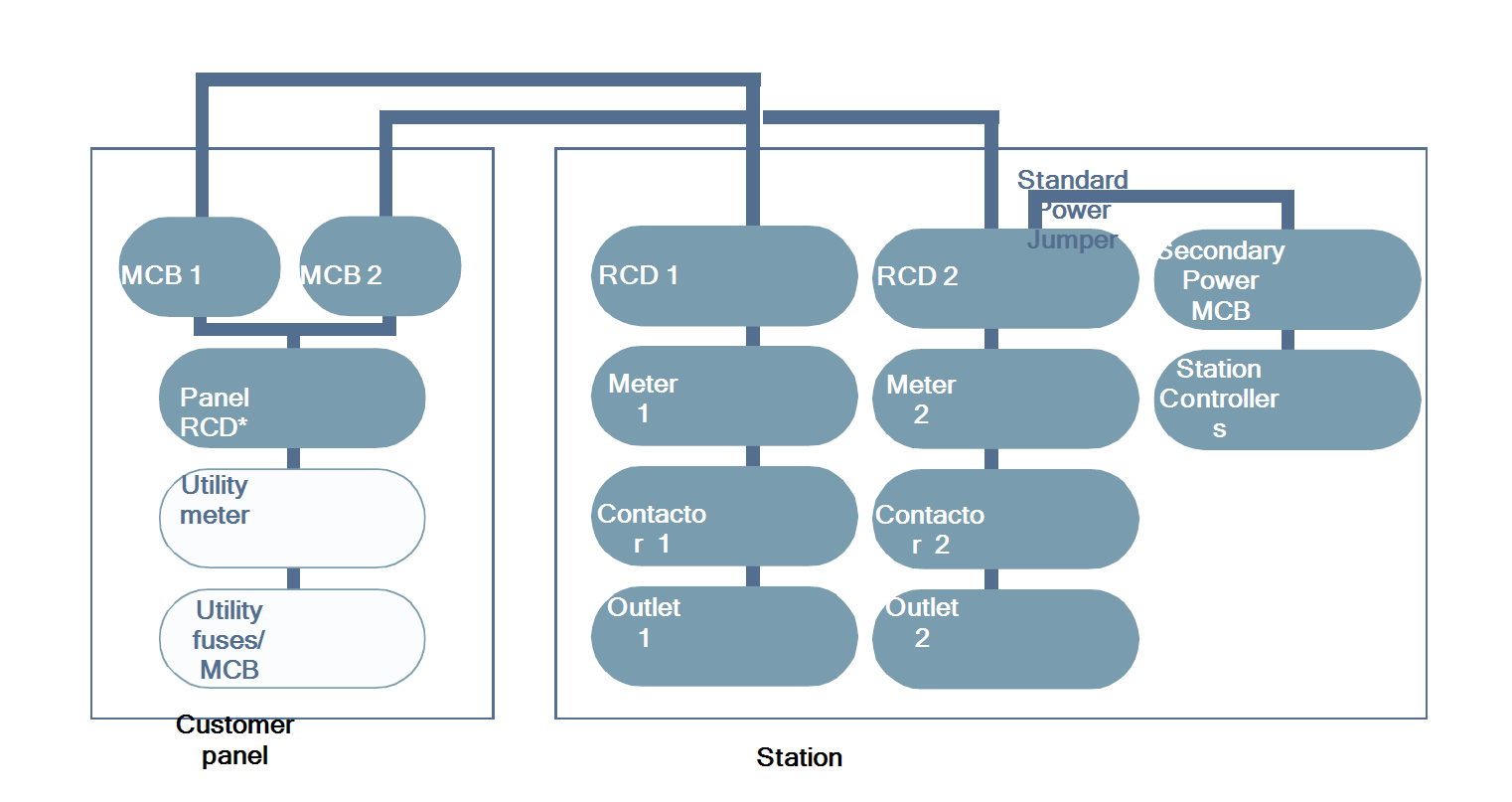
Standard Wiring, Single Port Station
![]()
* Panel RCD![]() Residual Current Device optional. Install according to all applicable codes and regulations, as needed.
Residual Current Device optional. Install according to all applicable codes and regulations, as needed.
**MCB![]() Miniature Circuit Breaker: Miniature Circuit Breaker
Miniature Circuit Breaker: Miniature Circuit Breaker
Three Phase Wiring

*RCCB![]() Residual Current Circuit Breaker: Residual-Current Circuit Breaker with Overcurrent Protection
Residual Current Circuit Breaker: Residual-Current Circuit Breaker with Overcurrent Protection
Single Phase Wiring
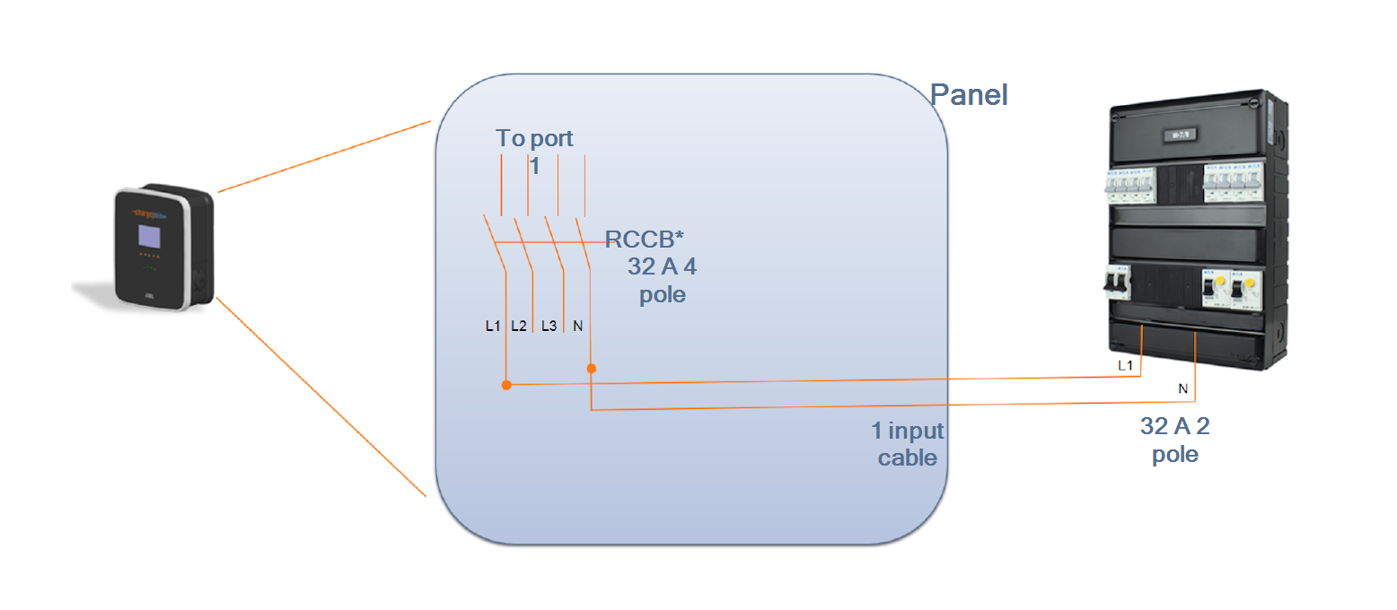
*RCCB![]() Residual Current Circuit Breaker: Residual-Current Circuit Breaker with Overcurrent Protection
Residual Current Circuit Breaker: Residual-Current Circuit Breaker with Overcurrent Protection
Standard Wiring, Dual Port Station
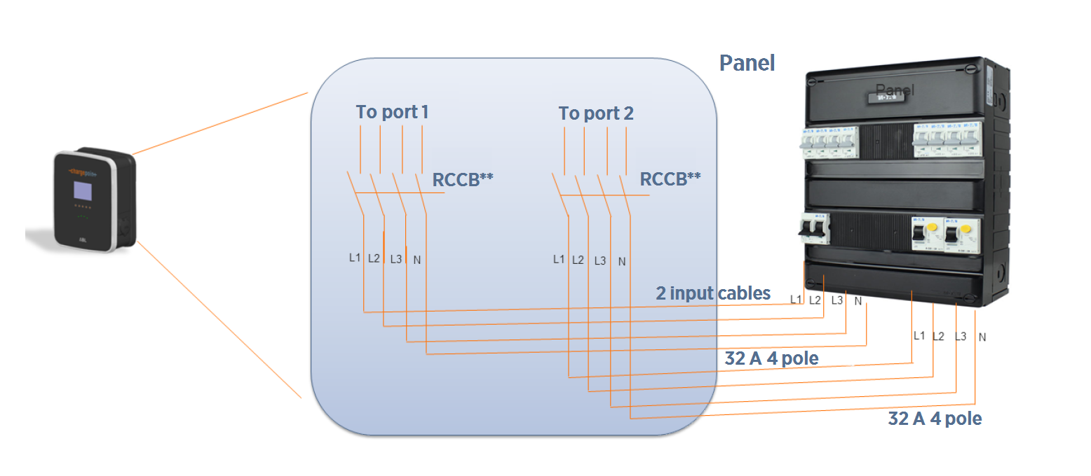
* Panel RCD![]() Residual Current Device optional. Install according to all applicable codes and regulations, as needed.
Residual Current Device optional. Install according to all applicable codes and regulations, as needed.
**RCCB![]() Residual Current Circuit Breaker: Residual-Current Circuit Breaker with Overcurrent Protection
Residual Current Circuit Breaker: Residual-Current Circuit Breaker with Overcurrent Protection
Circuit-Sharing Wiring (Dual Port Station Only)
To power a dual-port station using a single power cable, use the Cable Share Jumper. The L1 to L1 Cable Share Jumper is included with the CP4000. The L1 to L2 Cable Share Jumper is an alternative and is sold separately. Circuit sharing is available only for dual-port station configurations.
|
Output per Port |
Input Circuits |
Panel Breaker Required |
Breakers Required |
|---|---|---|---|
|
22 kW |
1 |
3-phase 63 A x 1 |
1 |
|
11 kW |
1 |
3-phase 32 A x 1 |
1 |
|
7.4 kW |
1 |
1-phase 63 A x 1 |
1 |
|
3.7 kW |
1 |
1-phase 32 A x 1 |
1 |
* Panel RCD![]() Residual Current Device optional. Install according to all applicable codes and regulations, as needed.
Residual Current Device optional. Install according to all applicable codes and regulations, as needed.
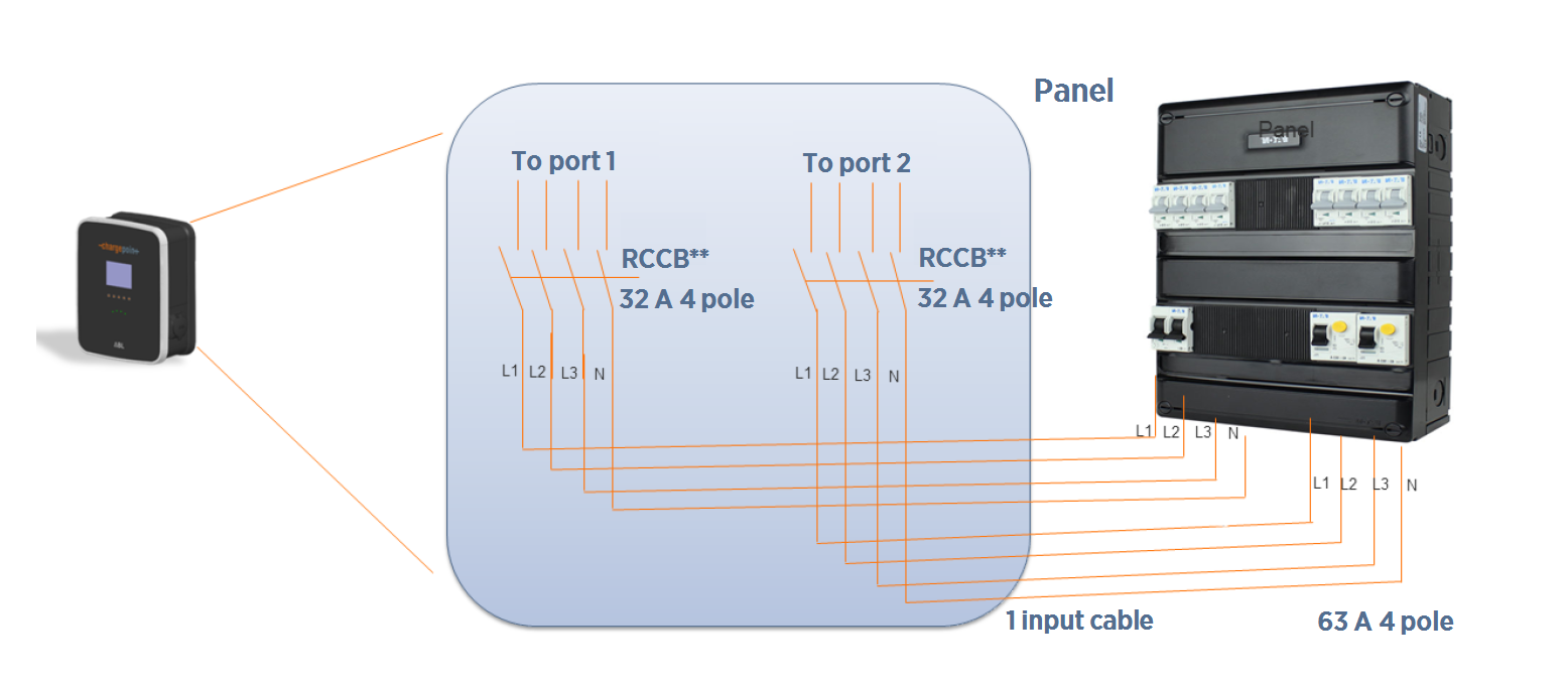
**RCCB![]() Residual Current Circuit Breaker: Residual-Current Circuit Breaker with Overcurrent Protection
Residual Current Circuit Breaker: Residual-Current Circuit Breaker with Overcurrent Protection
Meeting Power Supply Requirements
The charging station is designed for connection to and operation on rated voltages of 230 V (phase- neutral) or 400 V (phase-phase) at 50 Hz.
-
Comply to all regulatory requirements for low voltage installations according to IEC 60364-1 and IEC 60364-5-52.
-
Always connect the device to the protective earth conductor of the power source.
-
Reserve a power source exclusively for the charging station and ensure that it complies with HD 60364-7-722:2012.
-
Protect the charging station branch circuit in the panel (mains) with a suitable miniature circuit breaker (MCB
 Miniature Circuit Breaker).
Consult your electricity grid operator regarding requirements for local regulations. Depending on the desired rated power, the installation of the charging station may require registration with and/ or approval by your electricity grid operator.
Grounding Requirements
The CP4000 must be connected to a grounded, metal, permanent wiring system. An equipment- grounding conductor must be run with circuit conductors and connected to an equipment- grounding terminal on the CP4000.
A grounding conductor that complies with applicable codes must be grounded to earth at the service equipment or, when supplied by a separate system, at the supply transformer, or may be grounded to an earth electrode. Ensure the grounding conductor complies with all applicable codes.
Connect the Wiring
In areas with frequent thunderstorms, add surge protection at the service panel for all circuits.
Ensure all power and ground connections, especially those at the breaker and bus bar, are clean and tight. Remove all oxide from all conductors and terminals before connecting the wiring.
Complete a Standard Wiring Configuration
-
Remove the electrical tape from the ends of the power cables. If necessary, trim the power cables back, leaving enough cable to create a service loop of about 300 mm.
-
Strip the wires 13 mm. If the power cables have flexible wires, fit the stripped ends with wire end ferrules.
-
Use a Phillips screwdriver to loosen the lower screws in the terminal blocks.
-
Insert the Protective Earth (PE) wire into the PE terminal.
-
Tighten the lower screw on the PE terminal to no more than 3 Nm.
Connection Coding
Current-Carrying Conductor
L1
Phase 1
L2
Phase 2
L3
Phase 3
N
Neutral
PE
Protective earth
-
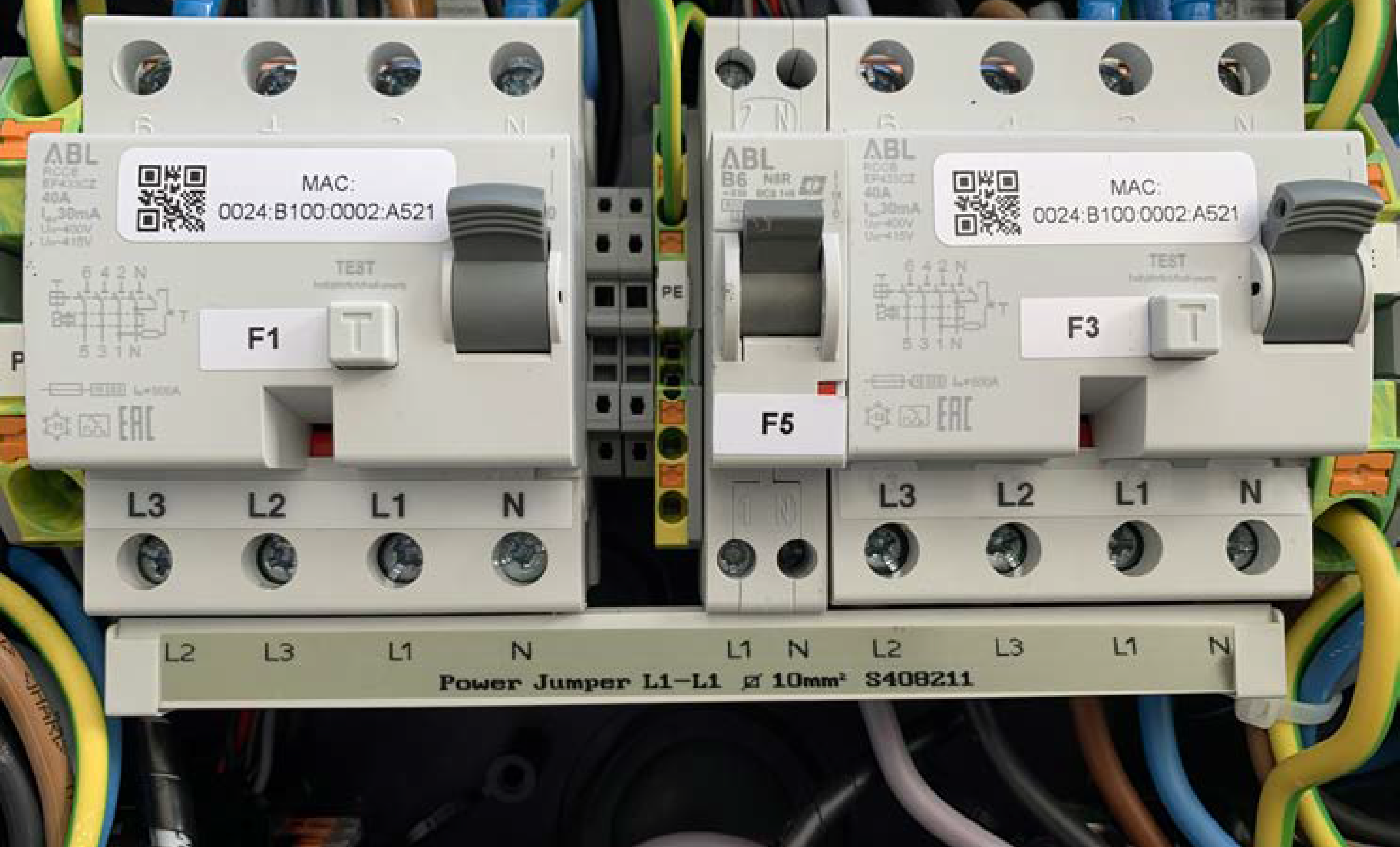
Connect the L1, L2, L3, and N wires to the right-hand terminal block.
Consider which one of the three possible orientations for L1, L2, and L3 you want to use for this particular station. If the site has more than one station, ensure that the stations rotate through the three possible wiring orders to distribute the load evenly. -
Label the terminal block with the correct phase rotation label.
Tighten the lower screws on the terminals to 3 Nm. -
For dual port stations, repeat this step for the second power cable, using the left-hand terminal block.
-
Take a picture of the completed terminal block wiring with labels to submit during pinpointing.
Continue to Close Up the Charging Station.
Complete a Circuit-Sharing Configuration (Dual Port Stations Only)
To share a single circuit between two ports:
-
Remove the standard power jumper (a) from below the right-hand terminal block. Properly recycle this power jumper, following all local regulations.
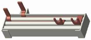
-
Carefully insert the ChargePoint Power Management Jumper (b) so that it spans both terminal blocks.
-
Remove the electrical tape from the ends of the power cables. If necessary, trim the power cables back, leaving enough cable to create a service loop of about 300 mm.
-
Strip the wires 13 mm. If the power cables have flexible wires, fit the stripped ends with wire end ferrules.
-
Using a Phillips screwdriver, loosen the lower screws in the terminal blocks.
-
Insert the Protective Earth (PE) wire into the PE terminal. Tighten the lower screw on the PE terminal to 3 Nm.
Connection Coding
Current-Carrying Conductor
L1
Phase 1
L2
Phase 2
L3
Phase 3
N
Neutral
PE
Protective earth
-
Connect the L1, L2, L3, and N wires to the right-hand terminal block.
Consider which one of the three possible orientations for L1, L2, and L3 you want to use for this particular station. If the site has more than one station, ensure that the stations rotate through the three possible wiring orders to distribute the load evenly. -
Label the terminal block with the correct phase rotation label.
-
Tighten the lower screws on the terminals to no more than 3 Nm.
-
Take a picture of the completed terminal block wiring with labels to submit during pinpointing.
Continue to Close Up the Charging Station.
Close Up the Charging Station
-
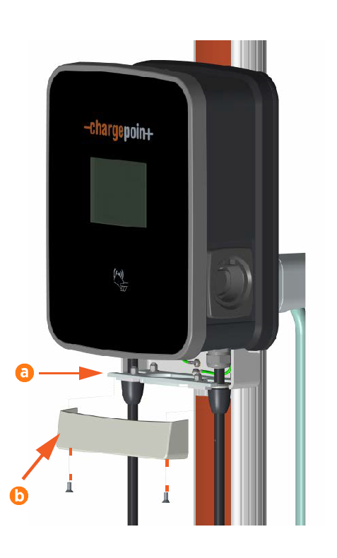
Lift the strain relief connectors (a) and tighten them onto the cable glands so that they fit snugly against the station mounting bracket.
-
Align the trim wall (b) so that it covers the bottom of the charging station and station mounting bracket. Use a T27 Torx driver and two M6 screws to secure the trim wall in place. Torque the screws to 6.5 Nm.
-
Carefully inspect the charging station to prepare it for closing.
-
Ensure all electrical connections are clean and torqued to specification.
-
Ensure all seals are firmly in place and in proper condition.
-
Wipe inside the charging station with a cloth to remove any debris left by the wires.
-
Collect any tools or fasteners inside the charging station.
-
Ensure all cables are laid properly and the power cables are connected correctly to their terminal blocks.
-
-
Replace the component cover.
-
Switch on the upstream breaker.
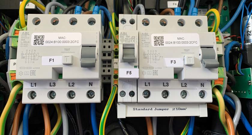
-
For dual port stations, switch on the left RCD
Residual Current Device (F1). -
Switch on the right RCD
Residual Current Device (F3). -
Switch on the middle MCB
Miniature Circuit Breaker (F5).The charging station establishes a connection to the power source.
-
Close the door, ensuring all wires are clear of the door and the latch clicks shut. Use the included key to lock the door.
-
Remove the key and put it in a safe place. Once the installation is complete, give it to the station owner.
-
Remove the protective plastic film from the door of the charging station.
Keep the label on the plastic film for its activation information in a later step.Do not leave the plastic film on the charging station for more than one day. Exposure to direct sun causes the plastic film to mar the front of the charging station.
