Introduction
The ChargePoint CP6000 is an all-purpose charging station for property owners, businesses, and municipalities. The CP6000 charging station can be mounted on a pedestal or a wall.
CP6000 charging stations are alternating current (AC) supply equipment. Once they are installed and activated, they are connected to the AC network.
- If the charging station is not installed, commissioned, or serviced by a ChargePoint certified technician using a ChargePoint-approved method, it is excluded from all ChargePoint and other warranties and ChargePoint is not responsible.
- You must be a licensed electrician and complete training at https://www.chargepoint.com/partners/training-certification to become ChargePoint certified and to access ChargePoint's web-based installer tools or ChargePoint Installer app.
CP6000 charging stations can be installed with single cable feeding both ports (circuit share) or with dual cables, one for each port.
Accessing Complete Documentation
Access documents at ChargePoint Product Reference Documentation.
|
Document |
Content |
Primary Audiences |
|
Datasheet |
Full station specifications |
Site designer, installer, and station owner |
|
Site Design Guide |
Civil, mechanical, and electrical guidelines to scope and construct the site |
Site designer or engineer of record |
|
Construction Signoff Form |
Checklists used by contractors to ensure the site is correctly completed and ready for product installation |
Site construction contractor |
|
Installation Guide |
Anchoring, wiring, and powering on |
Installer |
|
Operation and Maintenance Guide |
Operation and preventive maintenance information |
Station owner, facility manager, and technician |
|
Service Guide |
Component replacement procedures, including optional components |
Service technician |
|
Declaration of Conformity |
Statement of conformity with directives |
Purchasers and public |
Power Management
Using ChargePoint Power Management technology, sites can install more stations than would otherwise be supported by the available electrical service. A maximum aggregate load is defined for a group of charging stations. ChargePoint cloud-based services manage the individual power output of each station (or port) to ensure the maximum load is never exceeded.
A CP6000 charging station provides up to 32 A of output current to each charging port.
Site Requirements
Ensure that the appropriate wiring, circuit protection, and metering are in place at the installation location by reviewing the Site Design Guide, the Datasheet, and the wiring diagrams and grounding requirements in the chapter titled Connect Wiring.
Required Tools and Materials
To install CP6000 charging stations, you need the following tools:
|
|
T20 and T25 torx-end wrenches |
|
Wire stripper |
|
|
Mini-ratchet wrench |
|
Torx screwdriver (T25) |
|
|
Adjustable torque wrench nut size 4 mm and 24 mm |
|
#2 Pozidriv torque screwdriver |
|
|
4 mm ball-end hex wrench L wrench included, combined with T25 Torx
|
|
#3 Philips screwdriver |
|
|
Multimeter (solenoid type voltmeter preferred) |
|
Flat blade screwdriver (capable of controlling torque) |
|
|
Diagonal wire cutter |
|
Level |
|
|
Drill and tap for appropriate wall attachment hardware (wall mount stations only) |
|
10 mm wrench |
|
|
CMK |
|
Protective cut-proof gloves |


Wall mounting hardware requirements vary based on surfaces:
-
Masonry anchors rated for at least 318 kg (700 lb) of pull-out force.
-
Attachment hardware appropriate for mounting surface. For example, use
10 x 75 mm (3/8 x 3 in) lag bolts if mounting on a wooden wall.
Inspect the Box for Contents
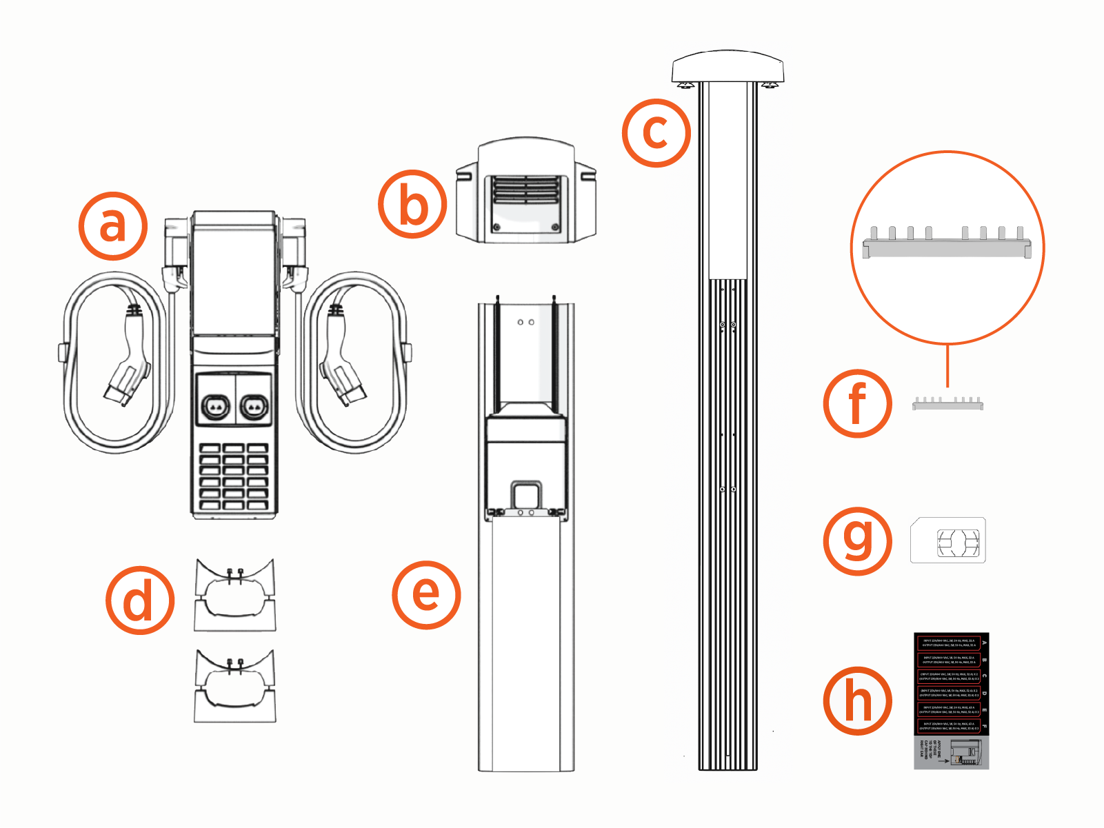
The CP6000 ships in multiple boxes. Check to make sure you have all of the following parts before beginning work.
(a) Head unit assembly
(b) Top cap
(c) Cable Management Kit (CMK![]() Cable Management Kit) - only stations with cables attached
Cable Management Kit) - only stations with cables attached
(d) Wall mount bracket kit (wall mount stations)
(e) Pedestal or wall mount enclosure
(f) Circuit share jumper kit
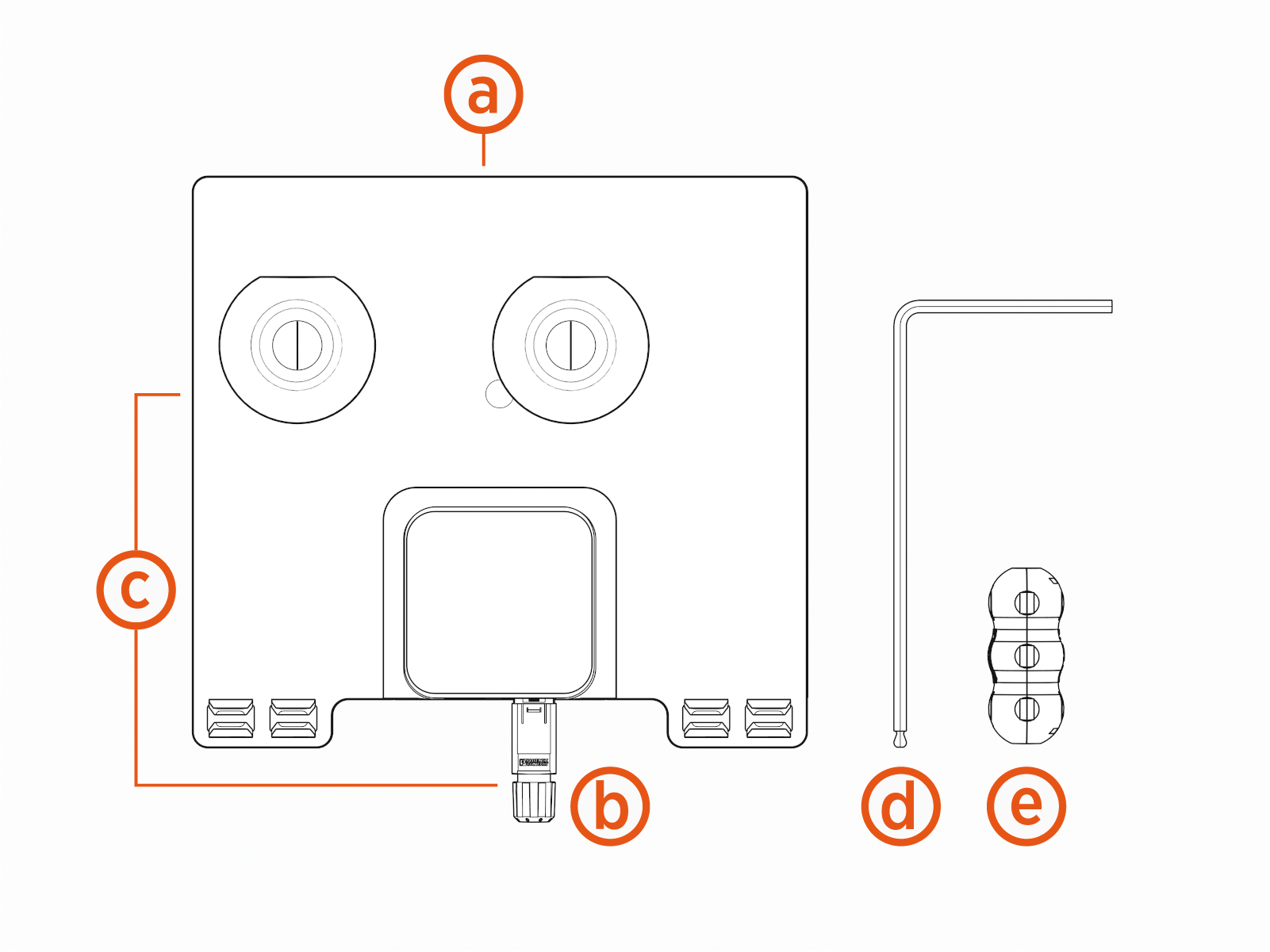
The charging station ships with an Ethernet kit (purchased separately). Check to make sure you have the following parts in the kit:
(a) Ethernet Module
(b) Accessory (the Ethernet connector)
(d) L-wrench
(e) Ferrite accessory
For assistance, go to chargepoint.com/support and contact technical support using the appropriate region-specific number. Order power management jumpers from Support if required.
CP6000 charging stations comes with two options:
Residual Current Circuit Breaker (RCCB
 Residual Current Circuit Breaker) per charging port or
Residual Circuit Breaker with Overload Protection (RCBO
Residual Current Breaker with Overload Protection) per charging port
Talk to your local ChargePoint contact and agree on the best solution for the installation.
When choosing RCBO![]() Residual Current Breaker with Overload Protection, a single input cable can be supplied to the charging station because of the share power management jumpers. The upstream cable will also be protected according to the national wiring regulations.
Residual Current Breaker with Overload Protection, a single input cable can be supplied to the charging station because of the share power management jumpers. The upstream cable will also be protected according to the national wiring regulations.
When choosing RCCB![]() Residual Current Circuit Breaker in certain countries, local wiring regulations will require that these stations shall be connected with two input power cables and an additional upstream Miniature Circuit Breaker (MCB
Residual Current Circuit Breaker in certain countries, local wiring regulations will require that these stations shall be connected with two input power cables and an additional upstream Miniature Circuit Breaker (MCB![]() Miniature Circuit Breaker). Make sure to follow the local regulations considering the maximum current delivered per charging port.
Miniature Circuit Breaker). Make sure to follow the local regulations considering the maximum current delivered per charging port.
If an upstream RCD![]() Residual Current Device will be used, ensure that the RCD
Residual Current Device will be used, ensure that the RCD![]() Residual Current Device fulfills the selectivity criteria. Either 30 mA (s) with selective tripping characteristic or 100 mA are required so both RCDs (RCCB
Residual Current Device fulfills the selectivity criteria. Either 30 mA (s) with selective tripping characteristic or 100 mA are required so both RCDs (RCCB![]() Residual Current Circuit Breaker in station and RCD
Residual Current Circuit Breaker in station and RCD![]() Residual Current Device in upstream circuit board) will be connected in series.
Residual Current Device in upstream circuit board) will be connected in series.
