Assemble the Station
To assemble the station, complete the following steps.
Connect the Head Assembly
Perform the following steps to connect the head assembly:
-
If you are setting the CP6000 charging station up to connect to a local Ethernet network, remove the RJ45 Ethernet connector from the Ethernet module in the kit.
If you are not setting up Ethernet capability, skip to step 2.

-
Lower the power plate cover or the Ethernet module, if applicable, into the pedestal housing.

-
Open the head assembly package.
-
Remove the head assembly from the packaging.
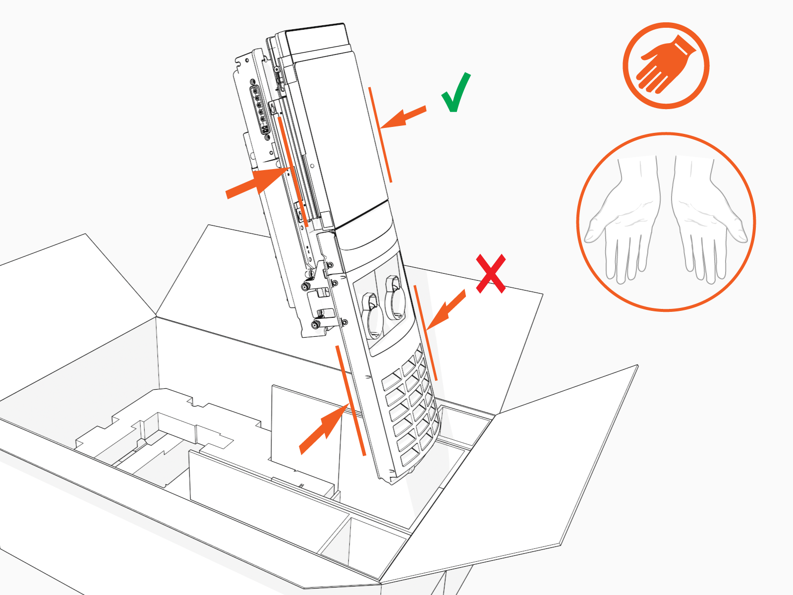 Hold the metal castings on the sides of the head assembly, not the plastic front cover, to avoid damaging the front cover.
 -
Align the rails on the head assembly with the pedestal and slide it into the pedestal housing.

The head assembly rests on the L-wrench connected to the side of the assembly.
-
Install the SIM card (stations being installed in Canada only).
The CP6000 includes two separate SIM cards – an embedded eSIM and a SIM slot that allows for swapping. This SIM slot supports physical SIM cards. An additional SIM card is taped to the head assembly. This SIM card is provided to increase coverage in Canada.
For Installations Located In Canada Only: Follow the next three steps to replace the pre-installed SIM card with the one taped to the station head unit.
For Installations Located in the United States : Discard this additional SIM card.
If the additional SIM card is multi-punch or break-apart, as in the example below, then make sure that you punch out the size matching the SIM being replaced in the unit. CP6000 uses Mini SIM (2FF). Card")
-
Mini SIM (2 FF)
The size and form of a physical SIM is known as its form factor (FF). SIMs come in a range of standard removable sizes ranging from 1 FF to 4 FF.-
Gently pull the top right corner of the screen-cover until the SIM-compartment can be reached, and rotate the SIM cover to access the SIM card.

-
Gently PUSH the existing SIM card with a flat-head screwdriver to eject the SIM card from its slot.
Make sure not to drop the SIM card in the base of the station.
-
Insert the additional SIM card with proper orientation and reverse the previous two steps to complete the replacement.

-
-
If you are installing the Ethernet module, visit Install the USB to Ethernet Module before continuing.
-
Loosen, but do not remove, the screws that secure the Control and Communications Unit (CCOM
 Control and Communications Module) to the head assembly. Some variants of CP6000 are shipped with cables pre-installed to the head unit. If your variant has the cables pre-installed, directly go to the step that details how to Remove the L-wrench..
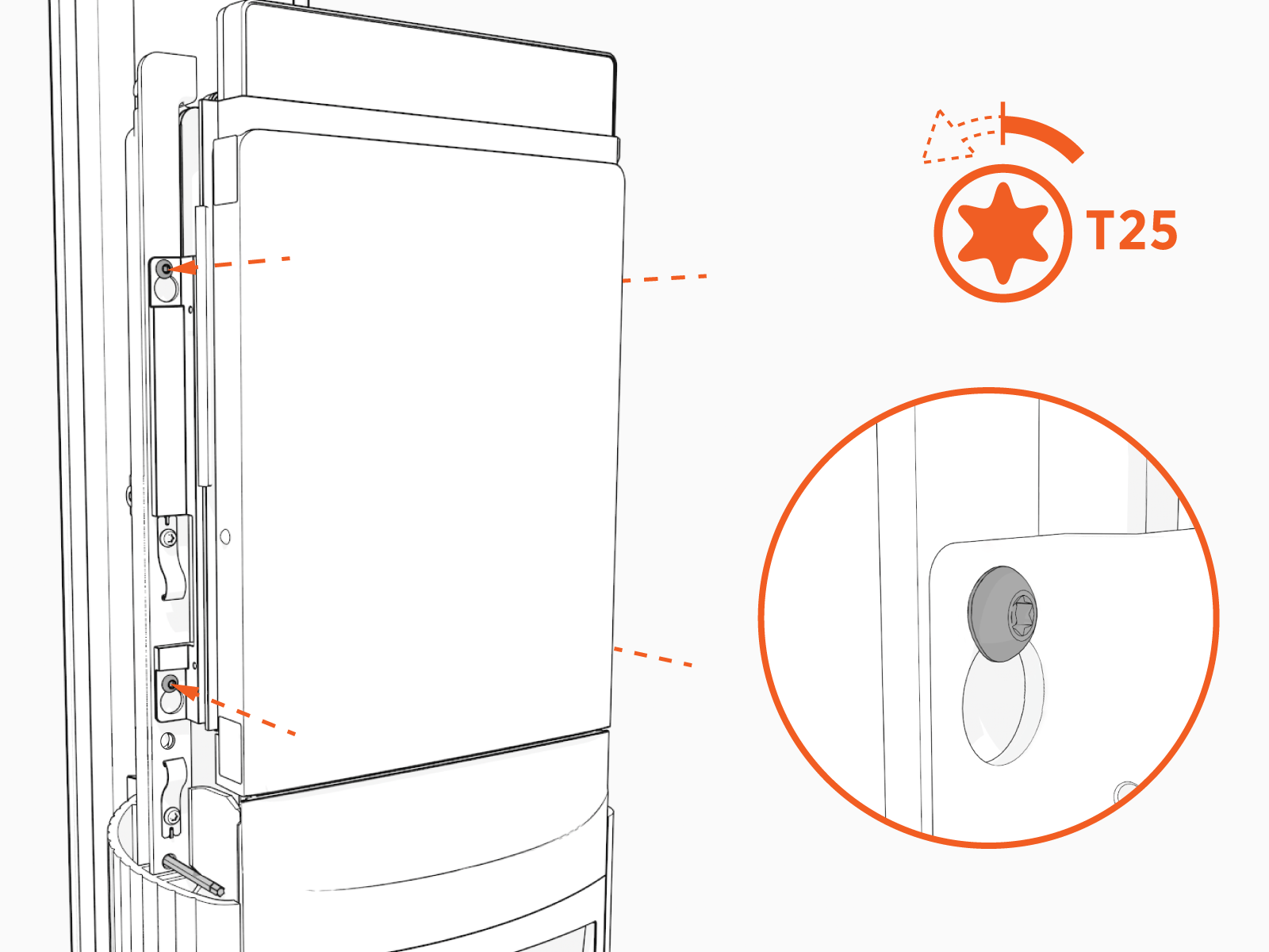
- Lift the CCOM Control and Communications Module up and tilt it away from the head assembly.
The bottom edge of the CCOM
Control and Communications Module rests on the upper edge of the holster assembly.
-
Ensure there is no visible damage to the connector pins.
Attach the smart cable by partially engaging one screw and then partially engaging the second screw.

-
On single port stations, attach the smart cable to the right side as you are facing the charging station. Connect the blank connector to the left side.

-
Torque both the top and bottom screws to 1.1 Nm (10 in-lb) to secure the smart cable.

-
Connect the RJ45 Ethernet cables from the smart cable assembly to the bottom of the CCOM
Control and Communications Module.Connect the Ethernet cable from the left charging cable to the left Ethernet port. Connect the Ethernet cable from the right charging cable to the right Ethernet port. The charging station will not work if the cables are connected to the wrong ports.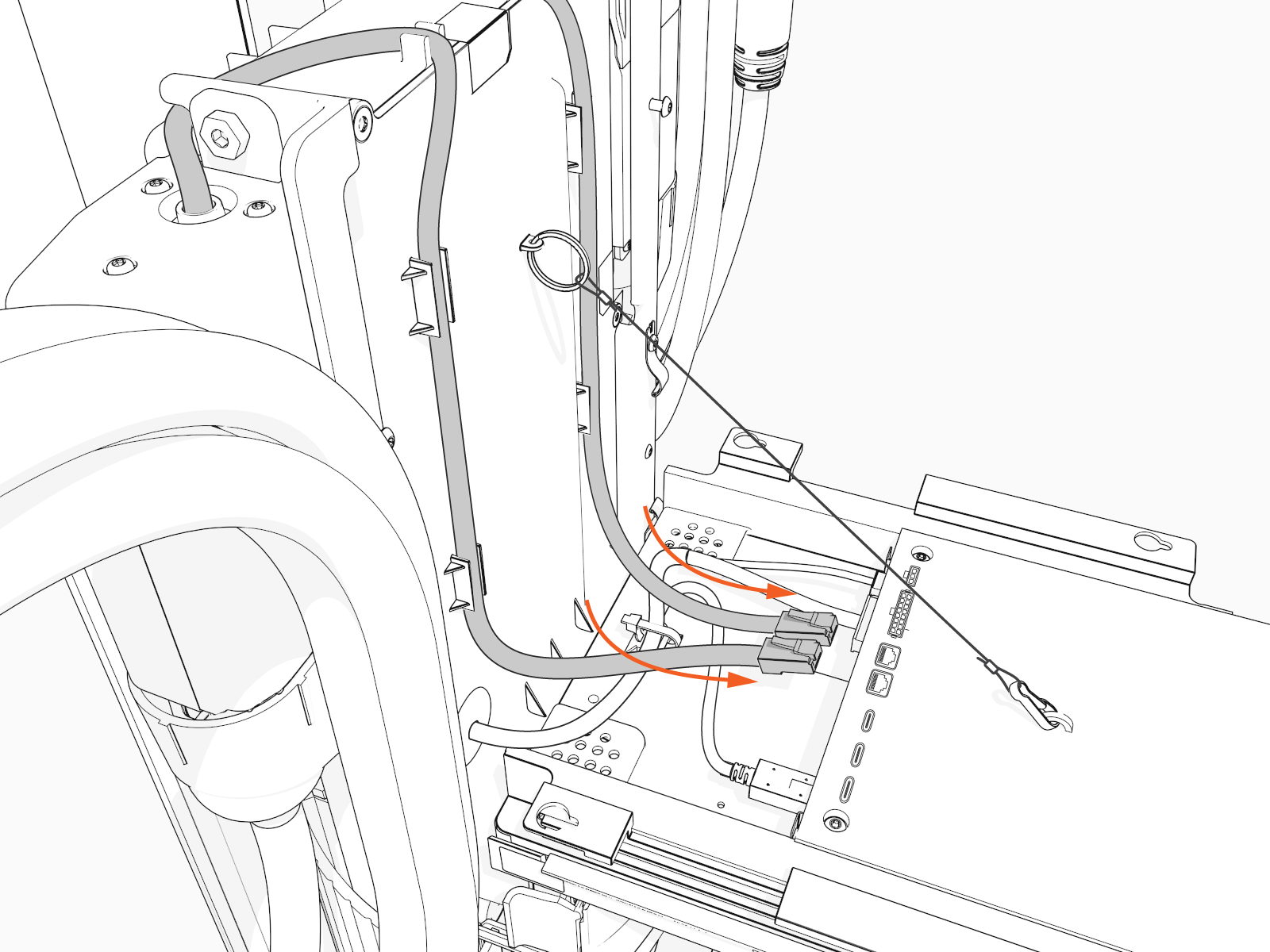
-
Slide the RJ45 Ethernet cables into the slots.

-
Raise the CCOM
Control and Communications Module and slide it into place on the head assembly. 
-
Torque the screws to 1.7 Nm (15 in-lb) to secure the CCOM
Control and Communications Module.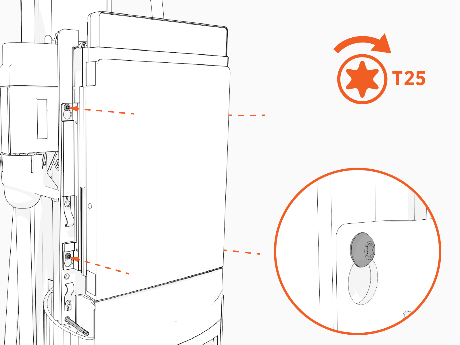
-

-
Slide the head assembly all the way into the pedestal housing.

-
Ensure the head assembly is fully seated.

-
Using the L-wrench, tighten two screws.

-
Take a picture of the activation label, remove the protective film, and give the protective film with the label to the station owner.

Install the Top Cap
Perform the following steps to install the top cap:
-
Slide the top cap onto the head assembly, adjusting as necessary to clear the charging cables, until it fits into place.

-
Torque two captive screws to 1.1 Nm (10 in-lb).
")
