CCB Faults Board Location
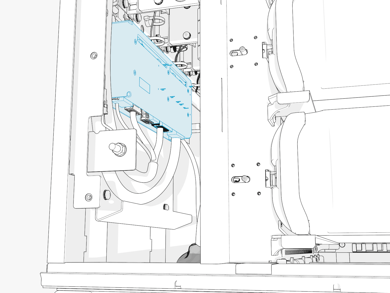
The illustrations below show the Power Block cooling controller (CCB) board location, key cable connections, and cable connector pin maps used during troubleshooting.
Front View for Locating the Boards for the CCB Faults
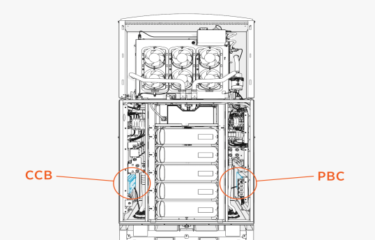
CCB Faults Board Location
178289-7
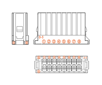
The rest of the connectors have the same connector type, but with less inputs. So, use the same logic to identify rows and columns for measurements.
CCB Faults
This section provides information on CCB faults, including fault characteristics, possible causes, and recommended troubleshooting steps.
PUMP_OVERCURRENT
|
Category |
Fault Source |
Fault Type |
Criticality |
|
Cooling |
CCB |
Hardware |
Critical |
Fault Description
If the pump current exceeds 8 A for more than 100 ms, the fault is declared. The average and maximum current values are noted and saved on PBC![]() Power Block Controller. The pump is disabled in EEPROM
Power Block Controller. The pump is disabled in EEPROM![]() Electrically Erasable Programmable Read-Only Memory and needs intervention from advanced users to reenable the pump after inspection or replacement.
Electrically Erasable Programmable Read-Only Memory and needs intervention from advanced users to reenable the pump after inspection or replacement.
Possible Causes
-
Shorting in the pump harness
-
Shorting in the motor winding, or locked rotor
-
Issue with CCB
Troubleshooting
-
Check the voltage on the pump through CCB node (chassis-shell) and confirm if it is reading 48 V. If it is not reading 48 V, then go to the step 2. If 48 V is present, then go to step 3.
-
Confirm if there is short in the CCB harness. Measure continuity across A1 (P_DC_PUMP_RET) and
B1 (P_DC_PUMP_POWER) on the connector going to CCB. If there is a short, then the CCB harness needs to be replaced. -
If the continuity test is good, measure continuity between Pin 1 and Pin 4 on P120 harness. If it shorted, it is possible that the pump has failed. Replace the pump and confirm if the issue goes away.
-
If pump replacement does not fix the issue, then the CCB board might have the fault, like shorted pins (feeding the connector), or a short on the traces carrying this voltage. Replace CCB to resolve the issue.
-
If none of the above steps work, please contact ChargePoint.
PUMP_DRYRUN_DETECTED
|
Category |
Fault Source |
Fault Type |
Criticality |
|
Cooling |
CCB |
Hardware |
Major |
Fault Description
If pump RPM is > 20 RPM and < 100 RPM for 5 s on commanding speed > 10, then this fault is declared. The fault is cleared and counter is reset. The pump will go back to operation.
PUMP_DRYRUN_EXCEEDED
|
Category |
Fault Source |
Fault Type |
Criticality |
|
Cooling |
CCB |
Hardware |
Critical |
Fault Description
If the pump dry run fault is detected 3 times in 24 hours, then this fault is declared.
Possible Causes
-
Low coolant level in the reservoir
-
Presence of air bubble in the coolant loop
-
Pump failure
-
Coolant leak
Troubleshooting
-
Check the coolant level to confirm if it is indeed low. Top up if it is less than LOW.
-
Possibility of air bubbles, so try to run the pump priming sub routine to clear them. See if the fault goes away. Also monitor the Pump RPM feedback in the CCB node of chassis-shell.
-
Verify if there is a coolant leak in the system.
-
If the issue persists, then replace the pump.
-
Contact ChargePoint for further debugging steps.
PUMP_OPENCIRCUIT_DETECTED
|
Category |
Fault Source |
Fault Type |
Criticality |
|
Cooling |
CCB |
Hardware |
Major |
Fault Description
Fault is declared when pump runs at speed >10% for 10 s, but reports pump current <0.5 A.
Troubleshooting
-
Check the RPM value reported on the pump at the time of failure (logs or chassis-shell). Each RPM number is associated with certain fault type. Reach out to ChargePoint with RPM number for further debugging steps.
PUMP_OPENCIRCUIT_EXCEEDED
|
Category |
Fault Source |
Fault Type |
Criticality |
|
Cooling |
CCB |
Hardware |
Critical |
Fault Description
The pump is disabled and the system is locked out when PUMP_OPENCIRCUIT_DETECTED fault repeats 3 times in 24 hours.
Possible Causes
-
Issue with pump harness
-
Pump failure
-
CCB failure
Troubleshooting
-
Check the pump voltage in the CCB node - if it reads 48 V then, there is a break in the harness.
-
Check the continuity in the pump harness. Measure between A1 on P5 connector and B1 on P5 connector and see if it reads open.
FAN_TRAY1_OVERCURRENT
|
Category |
Fault Source |
Fault Type |
Criticality |
|
Cooling |
CCB |
Hardware |
Critical |
Fault Description
This fault is declared if fan current consumption exceeds 8 A for 100 ms. The Fan Tray is disabled in EEPROM![]() Electrically Erasable Programmable Read-Only Memory and can only be cleared by a self-test or by an advanced user. Capture the fault in PBC
Electrically Erasable Programmable Read-Only Memory and can only be cleared by a self-test or by an advanced user. Capture the fault in PBC![]() Power Block Controller and store the average Fan Tray current value along with maximum current.
Power Block Controller and store the average Fan Tray current value along with maximum current.
Possible Causes
-
Short in fan harness
-
Shorting of fan winding
-
Locked rotor on fan
-
CCB failure
Troubleshooting
-
Confirm if there is anything blocking the fan blades from spinning.
-
Check the continuity between Pin 1 (FAN_RET_0) and 2 (FAN_PWR_0) on P109 connector (going to fans). Also, between Pins 5 (FAN_PWR_1) and 6 (FAN_RET_1). If there is a short in either of these measurements, then we have a short in the harness - go to step 3. If no issue, go to step 4.
-
Check if the short is from connector going from CCB or the junction in between. Measure continuity between Pins A1 (FAN_RET_0) and B1 (FAN_PWR_0) & Pins A3 (FAN_RET_1) and
B3 (FAN_PWR_1). If issue found, you need to replace that harness. -
If no issues were found in continuity test, replace the fan tray. Also re-enable the Fan 1 from EEPROM
 Electrically Erasable Programmable Read-Only Memory register.
 -
If the issue persists, replace CCB.
-
Contact ChargePoint for further debugging.
FAN_TRAY2_OVERCURRENT
|
Category |
Fault Source |
Fault Type |
Criticality |
|
Cooling |
CCB |
Hardware |
Critical |
Fault Description
This fault is declared if fan current consumption exceeds 8 A for 100 ms. The Fan Tray is disabled in EEPROM![]() Electrically Erasable Programmable Read-Only Memory and can only be cleared by a self-test or by an advanced user. Capture the fault in PBC
Electrically Erasable Programmable Read-Only Memory and can only be cleared by a self-test or by an advanced user. Capture the fault in PBC![]() Power Block Controller and store the average Fan Tray current value along with maximum current.
Power Block Controller and store the average Fan Tray current value along with maximum current.
Possible Causes
-
Short in fan harness
-
Shorting of fan winding
-
Locked rotor on fan
-
CCB failure
Troubleshooting
-
Confirm if there is anything blocking the fan blades from spinning.
-
Check the continuity between Pin 1 (FAN_RET_2) and 2 (FAN_PWR_2) on P110 connector (going to the fans). Also, between Pins 5 (FAN_RET_3) and 6 (FAN_PWR_3). If there is a short in either of these measurements, then we have a short in the harness - go to step 3. If no issue, go to step 4.
-
Check if the short is from P4 connector going from CCB. Measure continuity between Pins A6 (FAN_RET_2) and B6 (FAN_PWR_2) and Pins A8 (FAN_RET_3) and B8 (FAN_PWR_3). If an issue is found, then you need to replace that harness.
-
If no issues were found in continuity test, replace the fan tray. Also re-enable the fan 2 from EEPROM
Electrically Erasable Programmable Read-Only Memory register. -
If the issue persists, replace CCB.
-
Contact ChargePoint for further debugging.
FAN_TRAY3_OVERCURRENT
|
Category |
Fault Source |
Fault Type |
Criticality |
|
Cooling |
CCB |
Hardware |
Critical |
Fault Description
This fault is declared if fan current consumption exceeds 8 A for 100 ms. The Fan Tray is disabled in EEPROM![]() Electrically Erasable Programmable Read-Only Memory and can only be cleared by a self-test or by an advanced user. Capture the fault in PBC
Electrically Erasable Programmable Read-Only Memory and can only be cleared by a self-test or by an advanced user. Capture the fault in PBC![]() Power Block Controller and store the average Fan Tray current value along with the maximum current.
Power Block Controller and store the average Fan Tray current value along with the maximum current.
Possible Causes
-
Short in fan harness
-
Shorting of fan winding
-
Locked rotor on fan
-
CCB failure
Troubleshooting
-
Confirm if there is anything blocking the fan blades from spinning.
-
Check the continuity between Pin 1 (FAN_RET_4) and 2 (FAN_PWR_4) on P111 connector (going to fans). Also, between Pins 5 (FAN_RET_5) and 6 (FAN_PWR_5). If there is a short in either of these measurements, then we have a short in the harness - go to step 3. If no issue, go to step 4.
-
Check if the short is from connector going from CCB or the junction in between. Measure continuity between Pins A1 (FAN_RET_4) and B1 (FAN_PWR_4) and Pins A3 (FAN_RET_5) and B3 (FAN_PWR_5). If an issue is found, then that harness need to be replaced.
-
If no issues were found in continuity test, replace the fan tray. Also re-enable the Fan 3 from EEPROM
Electrically Erasable Programmable Read-Only Memory register. -
If the issue persists, replace CCB.
-
Contact ChargePoint for further debugging.
FAN_TRAY1_OPENCIRCUIT_DETECTED
|
Category |
Fault Source |
Fault Type |
Criticality |
|
Cooling |
CCB |
Hardware |
Critical |
Fault Description
The fault is declared if fan is run at >30% speed but, that fan current is <0.3 A for more than 10 s. This is a warning and not a fault. The system is operated as such until the self-test failure triggers a Service Call for fan tray replacement.
Possible Causes
-
Break in harness
-
Fan failure
-
CCB failure
Troubleshooting
-
Confirm if all the connectors are seated correctly on CCB and at the Wet Zone section.
-
Confirm if there is a break in wire carrying 48 V to fans. Check if the fan voltage on CCB (chassis-shell) reads 48 V. Also confirm by measuring it across Pins 1 and 2 on P109 connector and Pins 5 and 6.
-
If 48 V is not present, it is possible that there is a break in the wire carrying 48 V. Measure continuity from:
-
Pin A1 on P4 connector (on CCB) to Pin 1 on P109 connector.
-
Pin B1 on P4 connector (on CCB) to Pin 2 on P109 connector.
-
Pin A3 on P4 connector (on CCB) to Pin 5 on P109 connector.
-
Pin B3 on P4 connector (on CCB) to Pin 6 on P109 connector.
-
-
If there is a break in continuity, then we need to replace the harness to clear the fault.
-
If the fault exists with no failure in continuity, then replace the Fan Tray 1 to fix the issue.
-
If the issue persists after the fan tray replacement, then reach out to ChargePoint for further debugging steps.
FAN1_TRAY1_NO_FEEDBACK
|
Category |
Fault Source |
Fault Type |
Criticality |
|
Cooling |
CCB |
Hardware |
Minor |
Fault Description
The fault is declared if fan is run at >30% speed but, the fan RPM feedback is <2000 for more than 10 s. This is a warning and not a fault.
FAN2_TRAY1_NO_FEEDBACK
|
Category |
Fault Source |
Fault Type |
Criticality |
|
Cooling |
CCB |
Hardware |
Minor |
Fault Description
The fault is declared if fan is run at >30% speed but, the fan RPM feedback is <2000 for more than 10 s. This is a warning and not a Fault.
FAN_TRAY2_OPENCIRCUIT_DETECTED
|
Category |
Fault Source |
Fault Type |
Criticality |
|
Cooling |
CCB |
Hardware |
Critical |
Fault Description
The fault is declared if fan is run at >30% speed but, the fan current is <0.3 A for more than 10 s. This is a warning and not a fault. The system is operated asis until the self-test failure triggers a Service Call for the replacement of the fan tray.
Possible Causes
-
Break in harness
-
Fan failure
-
CCB failure
Troubleshooting
-
Confirm if all the connectors are seated correctly on CCB and at the Wet Zone section.
-
Confirm if there is a break in wire carrying 48 V to the fans. Check if fan voltage on CCB (chassis-shell) reads 48 V. Also confirm by measuring it across Pins 1 and 2 on P110 connector and Pins 5 and 6.
-
If 48 V is not present, it is possible that there is a break in wire carrying 48 V. Measure continuity from:
-
Pin A6 on P4 connector (on CCB) to Pin 1 on P110 connector..
-
Pin B6 on P4 connector (on CCB) to Pin 2 on P110 connector.
-
Pin A8 on P4 connector (on CCB) to Pin 5 on P110 connector.
-
Pin B8 on P4 connector (on CCB) to Pin 6 on P110 connector.
-
-
If there is a break in continuity, then we need to replace the harness to clear the fault.
-
If the fault exists with no failure in continuity, then replace the Fan Tray 2 to fix the issue.
-
If the issue persists after fan tray replacement, then reach out to ChargePoint for further debugging steps.
FAN1_TRAY2_NO_FEEDBACK
|
Category |
Fault Source |
Fault Type |
Criticality |
|
Cooling |
CCB |
Hardware |
Minor |
Fault Description
The fault is declared if the fan is run at >30% speed but, the fan RPM feedback is <2000 for more than 10 s. This is a warning and not a fault.
FAN2_TRAY2_NO_FEEDBACK
|
Category |
Fault Source |
Fault Type |
Criticality |
|
Cooling |
CCB |
Hardware |
Minor |
Fault Description
The fault is declared if the fan is run at >30% speed but, the fan RPM feedback is <2000 for more than 10 s. This is a warning and not a fault.
FAN_TRAY3_OPENCIRCUIT_DETECTED
|
Category |
Fault Source |
Fault Type |
Criticality |
|
Cooling |
CCB |
Hardware |
Critical |
Fault Description
The fault is declared if the fan is run at >30% speed but, the fan current is <0.3 A for more than 10 s. This is a warning and not a fault. The system is operated as is until the self-test failure triggers a Service Call for the fan tray's replacement.
Possible Causes
-
Break in harness
-
Fan failure
-
CCB failure
Troubleshooting
-
Confirm if all the connectors are seated correctly on CCB and at the Wet Zone section.
-
Confirm if there is a break in wire carrying 48 V to fans. Check if the fan voltage on CCB (chassis-shell) is read 48 V. Also confirm by measuring it across Pins 1 and 2 on P111 connector and Pins 5 and 6.
-
If 48 V is not present, it is possible that there is a break in wire carrying 48 V. Measure continuity from:
-
Pin A1 on P4 connector (on CCB) to Pin 1 on P111 connector.
-
Pin B1 on P4 connector (on CCB) to Pin 2 on P111 connector.
-
Pin A3 on P4 connector (on CCB) to Pin 5 on P111 connector.
-
Pin B3 on P4 connector (on CCB) to Pin 6 on P111 connector.
-
-
If there is a break in continuity, then we need to replace the harness to clear the fault.
-
If the fault exists with no failure in continuity, then replace the Fan Tray 3 to fix the issue.
COOLANT_LEVEL_SENSOR_DISCONNECTED
|
Category |
Fault Source |
Fault Type |
Criticality |
|
Cooling |
CCB |
Hardware |
Major |
Fault Description
This fault is declared when coolant sensor goes undetected for 120 s. This is a warning and does not stop system operation.
Possible Causes
-
Break in harness
-
Sensor failure
-
CCB failure
COOLANT_LEVEL_LOW
|
Category |
Fault Source |
Fault Type |
Criticality |
|
Cooling |
CCB |
Hardware |
Critical |
Fault Description
This fault is declared when coolant sensor detects coolant level is below its LOW threshold for 120 s. This is a warning and does not affect system operation.
A Service call is automatically created when it fails during self-test.
Possible Causes
-
Coolant level is low
-
Coolant sensor failure.
-
CCB failure
Troubleshooting
-
Check the coolant level in the reservoir and make sure it is topped up (if low).
-
If the coolant level is high and system still shows the fault, then make sure the sensor is still in its place and aligned the right way. Instances where the actual level sensing plate is wrongly fitted resulting in this error have been seen in the past.
-
Harness breaking and CCB failure should not result in this failure - highly unlikely but, cannot be ruled out. Contact ChargePoint for further debugging steps.
RTD_HX_INLET_DISCONNECTED
|
Category |
Fault Source |
Fault Type |
Criticality |
|
Cooling |
CCB |
Hardware |
Major |
Fault Description
This fault is declared when temperature sensor at the HEX![]() Heat Exchanger inlet reports >100 °C for 10 s. This is a warning and does not affect the system operation.
Heat Exchanger inlet reports >100 °C for 10 s. This is a warning and does not affect the system operation.
Service call is automatically created when it fails during self-test.
Possible Causes
-
Harness failure.
-
Sensor failure.
-
CCB failure.
Troubleshooting
-
Measure the continuity between Pins A4 and B4 on P5 connector going to CCB. If it measures an open, then issue is with the harness and needs replacement.
-
Inspect the connector on the Inlet RTD for any obvious disconnect or damage. If no issues, then the sensor might have failed. Contact ChargePoint for further steps.
RTD_HX_INLET_SHORTED
|
Category |
Fault Source |
Fault Type |
Criticality |
|
Cooling |
CCB |
Hardware |
Major |
Fault Description
This fault is declared when temperature sensor at the HEX![]() Heat Exchanger inlet reports -40 °C for 10 s. This is a warning and does not affect the system operation.
Heat Exchanger inlet reports -40 °C for 10 s. This is a warning and does not affect the system operation.
Service call is automatically created when it fails during self-test.
Possible Causes
-
Harness failure
-
Sensor failure
-
CCB failure
Troubleshooting
-
Measure the continuity between Pins A4 and B4 on P5 connector going to CCB. If it measures a short, then the issue is with the harness and needs replacement.
-
Inspect the connector on the Inlet RTD for any obvious disconnect or damage. If there are no issues, then the sensor might have failed. Contact ChargePoint for further steps.
RTD_HX_OUTLET_DISCONNECTED
|
Category |
Fault Source |
Fault Type |
Criticality |
|
Cooling |
CCB |
Hardware |
Major |
Fault Description
This fault is declared when temperature sensor at the HEX![]() Heat Exchanger outlet reports >100 °C for 10 s. This is a warning and does not affect the system operation.
Heat Exchanger outlet reports >100 °C for 10 s. This is a warning and does not affect the system operation.
Service call is automatically created when it fails during self-test.
Possible Causes
-
Harness failure
-
Sensor failure
-
CCB failure
Troubleshooting
-
Measure the continuity between Pins A5 and B5 on P5 connector going to CCB. If it measures an open, then issue is with the harness and needs replacement.
-
Inspect the connector on the HEX
Heat Exchanger Outlet RTD for any obvious disconnect or damage. If no issues, then sensor might have failed. Contact ChargePoint for further steps.
RTD_HX_OUTLET_SHORTED
|
Category |
Fault Source |
Fault Type |
Criticality |
|
Cooling |
CCB |
Hardware |
Major |
Fault Description
This fault is declared when temperature sensor at the HEX![]() Heat Exchanger outlet reports -40 °C for 10 s. This is a warning and does not affect the system operation.
Heat Exchanger outlet reports -40 °C for 10 s. This is a warning and does not affect the system operation.
Service call is automatically created when it fails during self-test.
Possible Causes
-
Harness failure
-
Sensor failure
-
CCB failure
Troubleshooting
-
Measure the continuity between Pins A5 and B5 on P5 connector going to CCB. If it measures a short, then the issue is with the harness and needs replacement.
-
Inspect the connector on the HEX
Heat Exchanger Outlet RTD for any obvious disconnect or damage. If no issues, then the sensor might have failed. Contact ChargePoint for further steps.
RTD_WETZONE_AMB_DISCONNECTED
|
Category |
Fault Source |
Fault Type |
Criticality |
|
Cooling |
CCB |
Hardware |
Major |
Fault Description
This fault is declared when wetzone ambient RTD reports >100 °C for 10 s. This is a warning and does not affect the system operation.
Service call is automatically created when it fails during self-test.
Possible Causes
-
Harness failure
-
Sensor failure
-
CCB failure
Troubleshooting
-
Measure the continuity between Pins A6 and B6 on P5 connector going to CCB. If it measures an open, then the issue is with the harness and needs replacement.
-
Inspect the connector on the Ambient Wetzone RTD for any obvious disconnect or damage. If no issues, then the sensor might have failed. Contact ChargePoint for further steps.
RTD_WETZONE_AMB_SHORTED
|
Category |
Fault Source |
Fault Type |
Criticality |
|
Cooling |
CCB |
Hardware |
Major |
Fault Description
This fault is declared when temperature sensor at the HEX![]() Heat Exchanger inlet reports -40 °C for 10 s. This is a warning and does not affect the system operation.
Heat Exchanger inlet reports -40 °C for 10 s. This is a warning and does not affect the system operation.
Service call automatically created when it fails during self-test.
Possible Causes
-
Harness failure
-
Sensor failure
-
CCB failure
Troubleshooting
-
Measure the continuity between Pins A6 and B6 on P5 connector going to CCB. If it measures an short, then the issue is with the harness and needs replacement.
-
Inspect the connector on the Ambient Wetzone RTD for any obvious disconnect or damage. If no issues, then the sensor might have failed. Contact ChargePoint for further steps.
CCB_BOARD_TEMP
|
Category |
Fault Source |
Fault Type |
Criticality |
|
Cooling |
CCB |
Hardware |
Critical |
Fault Description
The temperature sensing chip on CCB board reports board temperature as >80 °C. This is a warning and the system operates normally.
Service call is created automatically.
Possible Causes
-
Temp sensor is stuck in a bad state
-
I2C chip measuring this temp has failed on CCB
Troubleshooting
-
I2C chip measures this board temperature, so it is possible that it is stuck at a certain value. Reboot the CCB to see if the issue goes away (recommend Hard Power Cycle).
-
If the issue persists over power cycle, then replace the CCB board to fix the issue.
Contact ChargePoint if the issue persists.
CCB_12V_SUPPLY
|
Category |
Fault Source |
Fault Type |
Criticality |
|
Cooling |
CCB |
Hardware |
Critical |
Fault Description
12 V supply on CCB is used to control MOSFETs that turn ON/OFF the pump and fans. If this 12 V goes out of spec, DSP_12V_PGOOD signal goes low and then this fault is declared..
Possible Causes
-
DSP stuck at some point
-
Failure on CCB board
Troubleshooting
-
Power cycle to confirm if DSP is just stuck at some point bringing this 12 V down. If the issue persists after the power cycle then, see the following steps.
-
Replace CCB to fix the issue.
-
Contact ChargePoint if the issue persists.
