PBC Faults Board Location
The illustrations below show the Power Block controller (PBC![]() Power Block Controller) board location, key cable connections, and cable connector pin maps used during troubleshooting.
Power Block Controller) board location, key cable connections, and cable connector pin maps used during troubleshooting.
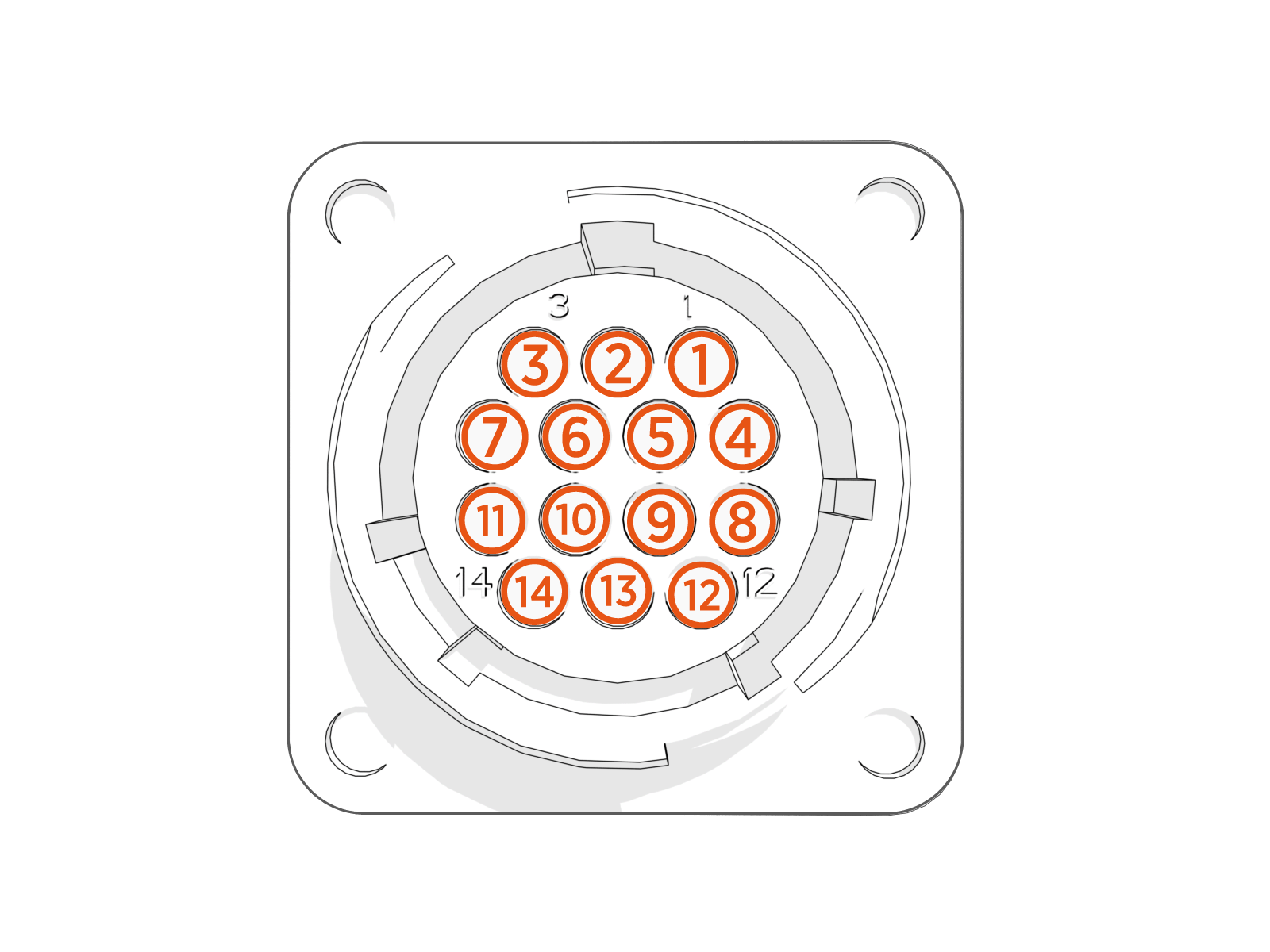
Front View for Locating the Boards for PBC Faults
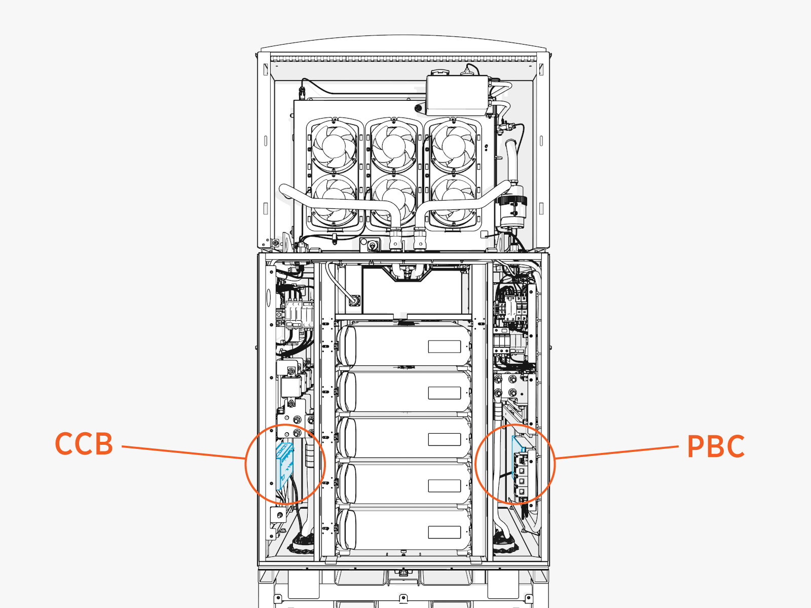
PBC Faults Board Location
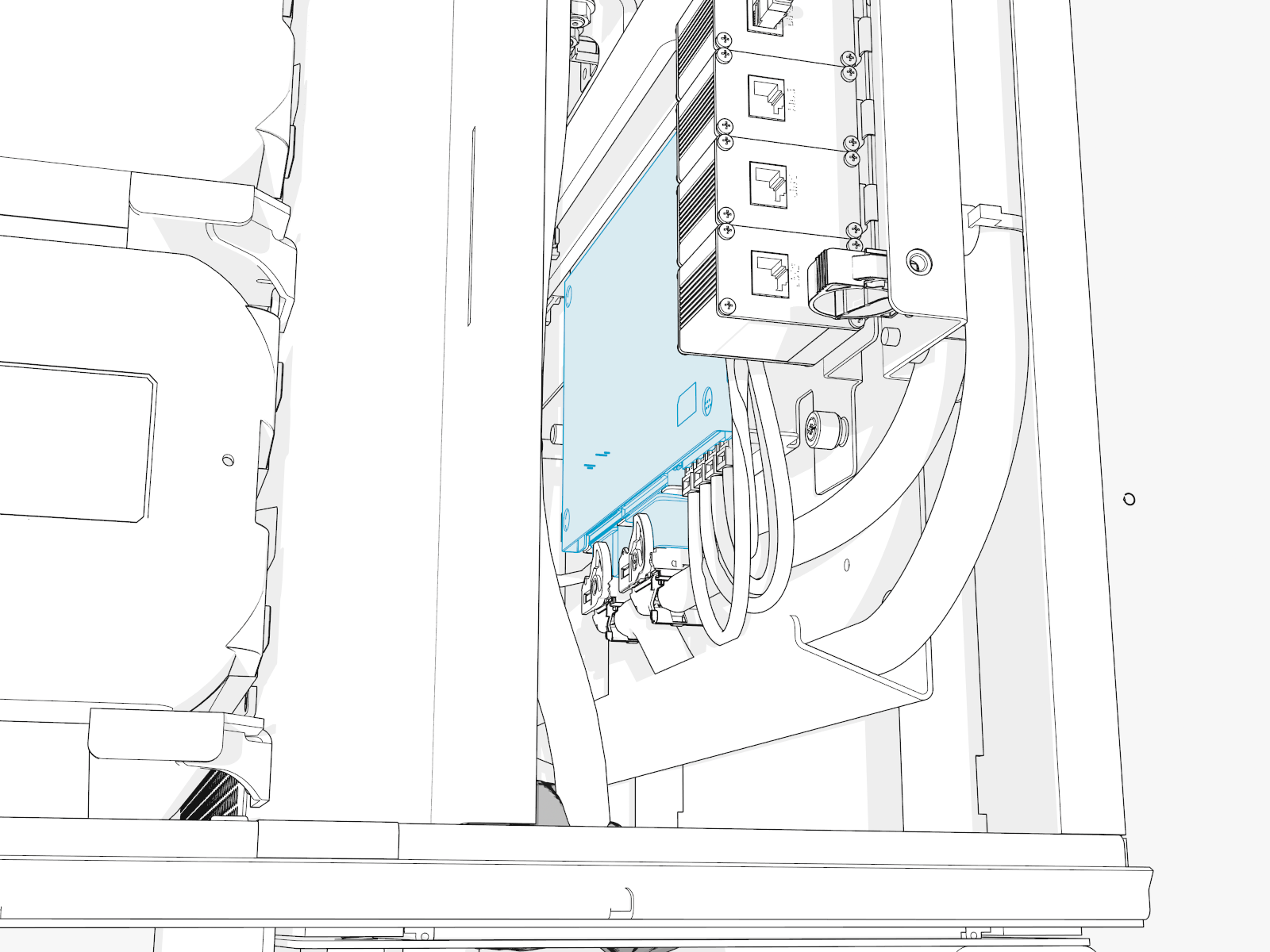
PBC Faults Cable Location
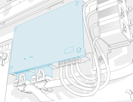
PBC-J108
PBC-J109
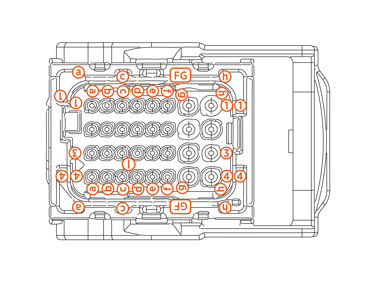
PBC-P148
PBC Faults
This section provides information on PBC![]() Power Block Controller faults, including fault characteristics, possible causes, and recommended troubleshooting steps.
Power Block Controller faults, including fault characteristics, possible causes, and recommended troubleshooting steps.
PBC_FAN1_OVERCURRENT
|
Category |
Fault Source |
Fault Type |
Criticality |
|
Cooling |
Dry zone fan bank 1 |
Hardware |
Major |
Fault Description
Fan 1 current consumption more than 4 A for 100 ms. Fan 1 is disabled and Power Block is set to derate to 50% of maximum available power.
Possible Causes
-
Short between wires due to a slice or a cut in insulation
-
Obstruction to fan fins
-
Internal fan failure
-
Connector broken leading to a short
Troubleshooting
-
Confirm if connectors going to PBC
 Power Block Controller and also to the fans are seated fully.
 -
Look for wiring continuity between PBC
Power Block Controller connector and Fan 1 connector. -
Measure continuity between M3 (Fan_PWR) and M4 (Fan_Ret) on P108 connector going to PBC
Power Block Controller.
-
-
If there is a short detected between PWR and RET line, then replace the harness.
-
If no short is measured, then replace the Dry zone fans to fix the issue.
-
Contact ChargePoint if the issue still persists.
PBC_FAN2_OVERCURRENT
|
Category |
Fault Source |
Fault Type |
Criticality |
|
Cooling |
Dry zone fan bank 2 |
Hardware |
Major |
Fault Description
Fan 1 current consumption more than 4 A for 100 ms. Fan 1 is disabled and Power Block is set to derate to 50% of maximum available power.
Possible Causes
-
Short between wires due to a slice or a cut in insulation
-
Obstruction to fan fins
-
Internal fan failure
-
Connector broken leading to a short
Troubleshooting
-
Confirm if connectors going to PBC
Power Block Controller and also to the fans are seated fully. -
Look for wiring continuity between PBC
Power Block Controller connector and Fan 1 connector. -
Measure continuity between M1 (Fan_PWR) and M2 (Fan_Ret) on P108 connector going to PBC
Power Block Controller.
-
-
If there is a short detected between PWR and RET line, then replace the harness.
-
If no short is measured, then replace the Dry zone fans to fix the issue.
-
Contact ChargePoint if the issue still persists.
PBC_FAN1_OPENCIRCUIT_DETECTED
|
Category |
Fault Source |
Fault Type |
Criticality |
|
Cooling |
Dry zone fan bank 1 |
Hardware |
Major |
Fault Description
Fan 1 current consumption less than 0.3 A per 100 s. Fan 1 is disabled and Power Block is operational and will derate if Power Modules report overheating.
Possible Causes
-
Break in PWR or GND
Ground wires feeding the PBC Power Block Controller -
Connector not seated fully
Troubleshooting
-
Confirm if connectors going to PBC
Power Block Controller and also to the fans are seated fully. -
Look for wiring continuity between PBC
Power Block Controller connector and Fan 1 connector. -
If no short is measured, then replace the Dry zone fans to fix the issue.
-
Measure between M3 (Fan_PWR) on P108 connector (going PBC
Power Block Controller) to Pin 1 on P148 (going to DRY-HEX Heat Exchanger. -
Measure between M4 (Fan_Ret) on P108 connector (going to PBC
Power Block Controller) and Pin 7 on P148 (going to DRY-HEX Heat Exchanger).
If continuity test in steps (a) and (b) passes, then replace DRY-HEX
Heat Exchanger for resolution. If steps (a) or (b) fail, then replace the harness. -
-
If the issue still persists after replacing DRY-HEX
Heat Exchanger, then contact ChargePoint if the issue still persists.
PBC_FAN1_SPEED_MISMATCH
|
Category |
Fault Source |
Fault Type |
Criticality |
|
Cooling |
Dry zone fan bank 1 |
Hardware/Software |
Major |
Fault Description
Fan 1 not running at desired speed. 20% difference between commanded speed and speed feedback.
Power Block is operational and will derate if Power Modules overheat.
Possible Causes
Fan is not receiving responding to speed commands
Troubleshooting
-
If Power Block operates without derating, then no change is necessary.
-
If Power Block is derating, then contact ChargePoint for further steps.
PBC_FAN2_OPENCIRCUIT_DETECTED
|
Category |
Fault Source |
Fault Type |
Criticality |
|
Cooling |
Dry zone fan bank 2 |
Hardware |
Major |
Fault Description
Fan 2 current consumption less than 0.3 A for 10 s.
Power Block is operational and will derate if Power Modules report overheating.
Possible Causes
-
Break in PWR or GND
Ground wires feeding the PBC Power Block Controller -
Connector not seated fully
Troubleshooting
-
Confirm if connectors going to PBC
Power Block Controller and also to fans are seated fully. -
Look for wiring continuity between the PBC
Power Block Controller connector and the Fan 2 connector.-
Measure between M1 (Fan_PWR) on P1 connector (going to PBC
Power Block Controller) to Pin 6 on P148 (going to DRY-HEX Heat Exchanger). -
Measure between M2 (Fan_Ret) on P1 connector (going to PBC
Power Block Controller) and Pin 2 on P148 (going to DRY-HEX Heat Exchanger). -
Measure continuity between Fan_PWR and Fan_Ret.
-
-
If continuity test in steps (a) and (b) passes, then replace DRY-HEX
Heat Exchanger for resolution. If steps ()a or (b) fail, then replace the harness. -
If issue persists after replacing DRY-HEX
Heat Exchanger, then contact ChargePoint for further steps.
PBC_FAN2_SPEED_MISMATCH
|
Category |
Fault Source |
Fault Type |
Criticality |
|
Cooling |
Dry zone fan bank 2 |
Hardware/Software |
Minor |
Fault Description
Fan 2 not running at desired speed. 20% difference between commanded speed and speed feedback.
Power Block is operational and will derate if Power Modules overheat.
Possible Causes
Fan not receiving or responding to speed commands
Troubleshooting
-
If Power Block operates without derating, then no change is necessary.
-
If Power Block is derating, then contact ChargePoint for further steps.
RTD_DRYZONE_AMB_DISCONNECTED
|
Category |
Fault Source |
Fault Type |
Criticality |
|
Sensor |
Dry zone RTD |
Hardware |
Major |
Fault Description
Dry zone RTD disconnected.
Fault shown when the Dry zone RTD temperature goes above 100 °C for 10 s.
Power Block is allowed to run without any derate, unless power modules report higher temperatures and trigger derate.
Possible Causes
-
Break in RTD feedback wire
-
Not properly seated PBC
Power Block Controller connector P108
Troubleshooting
-
Reseat connector P148 and confirm if it fixes the issue.
-
Measure continuity between Pin J3 (T1_OUT) on P108 (going to PBC
Power Block Controller) and Pin 1 on P149. Also between Pin J4 (T1_RET) on P108 (going to PBC Power Block Controller) and Pin 2 on P148. -
If no continuity, then issue might be a break in the feedback wire.
-
Measure resistance across between Pin J3 and Pin J4 on P108.
-
Contact ChargePoint if the issue persists.
RTD_DRYZONE_AMB_SHORTED
|
Category |
Fault Source |
Fault Type |
Criticality |
|
Sensor |
Dry zone RTD |
Hardware |
Major |
Fault Description
Dry zone RTD Shorted.
If the temperature is reading -40° C for more than 10 s.
Power Block is allowed to run without any derate, unless Power Modules report higher temperatures and trigger the derate.
Possible Causes
-
Short in RTD feedback wire
-
Slice or cut in wire shorting to GND
Ground
Troubleshooting
-
Reseat connector P148 and confirm if it fixes the issue.
-
Measure continuity between Pin J3 (T1_OUT) on P108 (going to PBC
Power Block Controller) and Pin 1 on P149. Also between Pin J4 (T1_RET) on P108 (going to PBC Power Block Controller) and Pin 2 on P148. -
If there is a short detected, then replace the harness to fix the issue.
-
Measure resistance across between Pin J3 and Pin J4 on P108 to measure zero (if shorted).
-
Contact ChargePoint if the issue persists.
PB_AC-IN_SURGE_OPEN
|
Category |
Fault Source |
Fault Type |
Criticality |
|
Sensor |
Surge Arrestor |
Hardware |
Critical |
Fault Description
AC-IN surge suppressor cartridge is open or failed. Fault reported every 1 s.
Possible surge event if this happens on a unit installed in the field and was operational for some time.
Might be faulty hardware or wiring if it is seen in a brand new install.
Possible Causes
-
Feedback wire compromised
-
Real surge event in the field
Troubleshooting
-
Do a visual inspection of the surge cartridge - if RED
Route Enforcement Data then it's bad - replace the surge arrestor to fix the issue. Investigate if there was an actual surge event and inspect rest of the surge arrestors. If GREEN then it's good, continue to Step 2. -
To confirm the feedback wiring is good, measure continuity from Pin H4 (SURGE_NC_TRIP2) on P108 (going to PBC
Power Block Controller) to ACSRG1 (SURGE_NC_TRIP2) underneath the AC surge arrestor cartridge. Also, continuity between J1 (SURGE_NC_TRIP1) on P108 (going to PBC Power Block Controller) and ACSRG2 (underneath the surge arrestor). -
If wiring is confirmed good, then replace the failed surge cartridges.
PB_DC-IN_SURGE_OPEN
|
Category |
Fault Source |
Fault Type |
Criticality |
|
Sensor |
Surge Arrestor |
Hardware |
Critical |
Fault Description
DC-IN surge suppressor cartridge is open/failed. Fault reported every 1 s.
Possible surge event if this happens on a unit installed in the field and was operational for some time.
Might be faulty hardware or wiring if it is seen in a brand new install.
Possible Causes
-
Feedback wire compromised
-
Real surge event in the field
Troubleshooting
-
Do a visual inspection of surge cartridge - if RED
Route Enforcement Data then bad, if GREEN then good. -
To confirm the feedback wiring is good, measure continuity from Pin K2 (SURGE_COM_TRIP1) on P108 (going to PBC
Power Block Controller) to DCINSRG2 (underneath the DC-in surge arrestor cartridge). Also, continuity between G3 (SURGE_NC_TRIP1) on P108 (going to PBC Power Block Controller) and DCINSRG2 (underneath the surge arrestor). -
If the wiring is confirmed good, then replace the failed surge cartridges.
PB_DC-OUT-A_SURGE_OPEN
|
Category |
Fault Source |
Fault Type |
Criticality |
|
Sensor |
Surge Arrestor |
Hardware |
Critical |
Fault Description
DC bus bar A surge suppressor cartridge is open or failed. Fault reported every 1 s.
Possible surge event if this happens on a unit installed in the field and was operational for some time.
Might be faulty hardware or wiring if it is seen in a brand new install.
Possible Causes
-
Feedback wire compromised
-
Real surge event in the field
Troubleshooting
-
Do visual inspection of surge cartridge if RED
Route Enforcement Data then it's bad - replace the surge arrestor to fix the issue. Investigate if there was an actual surge event and inspect rest of the surge arrestors. If GREEN then it's good, continue to Step 2. -
To confirm the feedback wiring is good, measure continuity from Pin K1 (SURGE_COM_TRIP4) on P108 (going to PBC
Power Block Controller) to DCASRG1 (underneath the DC-out-B surge arrestor cartridge). Also, continuity between L1 (SURGE_NC_TRIP4) on P108 (going to PBC Power Block Controller) and DCASRG2 (underneath the surge arrestor). -
If wiring is confirmed good, then replace the failed surge cartridges.
PB_DC-OUT-B_SURGE_OPEN
|
Category |
Fault Source |
Fault Type |
Criticality |
|
Sensor |
Surge Arrestor |
Hardware |
Critical |
Fault Description
DC bus bar B surge suppressor cartridge is open or failed. Fault reported every 1 s.
Possible surge event if this happens on a unit installed in the field and was operational for some time.
Might be faulty hardware or wiring if it is seen in a brand new install.
Possible Causes
-
Feedback wire compromised
-
Real surge event in the field
Troubleshooting
-
Do a visual inspection of surge cartridge - if RED
Route Enforcement Data then it's bad - replace the surge arrestor to fix the issue. Investigate if there was an actual surge event and inspect rest of the surge arrestors. If GREEN then it's good, continue to Step 2. -
To confirm the feedback wiring is good, measure continuity from Pin L4 (SURGE_COM_TRIP3) on P108 (going to PBC
Power Block Controller) to DCBSRG1 (underneath the DC-Out-B surge arrestor cartridge). Also, measure continuity between K4 (SURGE_NC_TRIP3) on P108 (going to PBC Power Block Controller) and DCBSRG2 (underneath the surge arrestor). -
If wiring is confirmed good, then replace the failed surge cartridges.
PB_48V-EXT_SURGE_OPEN
|
Category |
Fault Source |
Fault Type |
Criticality |
|
Sensor |
Surge Arrestor |
Hardware |
Critical |
Fault Description
48V_EXT surge suppressor cartridge is open or failed.
Possible surge event if this happens on a unit installed in the field and was operational for some time.
Might be faulty hardware or wiring if it is seen in a brand new install.
Possible Causes
-
Feedback wire compromised
-
Real surge event in the field
Troubleshooting
-
Do a visual inspection of the surge cartridge - if RED
Route Enforcement Data then it's bad, if GREEN then it's good. -
To confirm the feedback wiring is good, measure continuity from Pin H3 (SURGE_COM_TRIP5) on P108 (going to PBC
Power Block Controller) to LVSRG1 (underneath the LV Low Voltage Surge arrestor cartridge). Also, measure continuity between E4 (SURGE_NC_TRIP5) on P108 (going to PBC Power Block Controller) and LVSRG2 (underneath the LV Low Voltage surge arrestor cartridge) -
If wiring is confirmed good, then replace the failed surge cartridges.
PB_AC-IN_THERMAL_SW
|
Category |
Fault Source |
Fault Type |
Criticality |
|
Sensor |
Thermal Switch |
Hardware |
Critical |
Fault Description
Thermal switches on AC-IN terminals are open. Power Block is derated to 50% operation.
If the thermal switches open in derated condition or 3 times within 24 hours, then PBC![]() Power Block Controller shall lockout the Power Block.
Power Block Controller shall lockout the Power Block.
Possible Causes
-
Feedback wire compromised
-
The thermal swich might be not making good contact with the bus bar
Troubleshooting
-
To confirm the feedback wiring is good, measure continuity from Pin K3 (THER_SW1_RET) on P108 (going to PBC
Power Block Controller) to L1IN (ACIN TSWITCH - A15). Also, measure continuity between L3 (THER_SW1) on P108 (going to PBC Power Block Controller) and L3OUT(ACIN TSWITCH - A15) -
If the wiring is confirmed good, then locate the thermal switch and confirm the seating on the bus bar. Also make sure the connectors on the switch are not loose. If everything seems good, then reach out to ChargePoint.
-
If the continuity issue is located, then we might have to replace the harness after locating the exact point of break. Contact ChargePoint.
PB_DC-IN_THERMAL_SW
|
Category |
Fault Source |
Fault Type |
Criticality |
|
Sensor |
Thermal Switch |
Hardware |
Critical |
Fault Description
Thermal switches on DC-IN terminals are open. Power Block is derated to 50% operation.
If the thermal switches open in derated condition or 3 times within 24 hours, then PBC![]() Power Block Controller shall lockout the Power Block.
Power Block Controller shall lockout the Power Block.
Possible Causes
-
Feedback wire compromised
-
The thermal switch might not be making good contact with the bus bar
Troubleshooting
-
To confirm the feedback wiring is good, measure continuity from Pin L2 (THER_SW2) on P108 (going to PBC
Power Block Controller) to P47 (DCIN). Also, measure continuity between H2 (THER_SW2_RET) on P108 (going to PBC Power Block Controller) and P51 (DCIN TSWITCH). -
If the wiring is confirmed good, then locate the thermal switch and confirm the seating on the bus bar. Also make sure the connectors on the switch are not lose. If everything seems good, then reach out to reach out to ChargePoint.
-
If the continuity issue is located, then we might have to replace the harness after locating the exact point of break. Contact ChargePoint.
PB_DC-OUT-A_THERMAL_SW
|
Category |
Fault Source |
Fault Type |
Criticality |
|
Sensor |
Thermal Switch |
Hardware |
Critical |
Fault Description
Thermal switches on DC_OUT-A terminals are open. Power Block is derated to 50% operation.
If the thermal switches open in derated condition or 3 times within 24 hours, then PBC![]() Power Block Controller shall lockout the Power Block.
Power Block Controller shall lockout the Power Block.
Possible Causes
-
Feedback wire compromised
-
The thermal switch might be not making good contact with the bus bar
Troubleshooting
-
To confirm the feedback wiring is good, measure continuity from Pin C3 (THER_SW3_RET) on P108 (going to PBC
Power Block Controller) to J42 (DC_OUT-A). Also, measure continuity between C4 (THER_SW3) on P108 (going to PBC Power Block Controller) and P43 (DC_OUT-A). -
If wiring is confirmed good, then locate the thermal switch and confirm the seating on the bus bar. Also make sure the connectors on the switch are not lose. If everything seems good, then reach out to ChargePoint for further steps.
-
If the continuity issue is located, then we might have to replace the harness after locating the exact point of break. Contact ChargePoint for further steps.
PB_DC-OUT-B_THERMAL_SW
|
Category |
Fault Source |
Fault Type |
Criticality |
|
Sensor |
Thermal Switch |
Hardware |
Critical |
Fault Description
Thermal switches on DC_OUT-B terminals are open. Power Block is derated to 50% operation.
If the thermal switches open in derated condition or 3 times within 24 hours, then PBC![]() Power Block Controller shall lockout the Power Block.
Power Block Controller shall lockout the Power Block.
Possible Causes
-
Feedback wire compromised
-
The thermal swich might be not making good contact with the bus bar
Troubleshooting
-
To confirm the feedback wiring is good, measure continuity from Pin D4 (THER_SW4_RET) on P108 (going to PBC
Power Block Controller) to J45 (DC_OUT-B). Also, measure continuity between E1 (THER_SW4) on P108 (going to PBC Power Block Controller) and P44 (DC_OUT-B). -
If wiring is confirmed good, then locate the thermal switch and confirm the seating on the bus bar. Also make sure the connectors on the switch are not loose. If everything seem good, then reach out to ChargePoint for further steps.
-
If the continuity issue is located, then we might have to replace the harness after locating the exact point of break. Contact ChargePoint for further steps.
PB_DRYZONE_DOOR_OPEN
|
Category |
Fault Source |
Fault Type |
Criticality |
|
Sensor |
Reed Switch |
Hardware |
Emergency |
Fault Description
Dry zone door is open. PBC![]() Power Block Controller shuts down the Power Block in controlled manner (if happened during a session). PBC
Power Block Controller shuts down the Power Block in controlled manner (if happened during a session). PBC![]() Power Block Controller also commands to open the shunt trip breaker through Aux PS.
Power Block Controller also commands to open the shunt trip breaker through Aux PS.
Possible Causes
-
Door is open
-
Reed sensor feedback is compromised
-
Sensor is misaligned with magnet or missing from its position
Troubleshooting
-
Confirm if the Wetzone Front door is open.
-
Look for the magnet and the sensor on the Wetzone door (Front Top door). Confirm the presence of both and that they are aligned with each other on closing the door. It need not touch each other but, as long as they are in the vicinity - 15 mm.
-
Measuring continuity of the feedback wire from Reed1 Pin SP19 (Sensor wire on Main Door - covering Power Modules) going to Reed1 - Pin C4 on P198-109 on PBC
Power Block Controller. Also, continuity between SEP20 (on the sensor) and REED1_RET - Pin D4 on P198-109. -
If there is no continuity, then the feedback wire/harness is broken. Contact ChargePoint if the issue persists.
-
If continuity is good, then use an external magnet and place it around the sensor. Check if the sensor feedback on chassis-shell changes when the magnet is around the sensor. If the feedback changes, then the sensor is bad and needs replacement.
PB_WETZONE_FRONT_DOOR_OPEN
|
Category |
Fault Source |
Fault Type |
Criticality |
|
Sensor |
Reed Switch |
Hardware |
Emergency |
Fault Description
Wet zone door is open. PBC![]() Power Block Controller shuts down the Power Block in controlled manner (if happened during a session). PBC
Power Block Controller shuts down the Power Block in controlled manner (if happened during a session). PBC![]() Power Block Controller also commands to open the shunt trip breaker through Aux PS.
Power Block Controller also commands to open the shunt trip breaker through Aux PS.
Possible Causes
-
Door is open
-
Reed sensor feedback is compromised
-
Sensor is misaligned with magnet or missing from its position
Troubleshooting
-
Confirm if the Dry zone is open.
-
Look for the magnet and the sensor on the Dry zone door. Confirm the presence of both and that they are aligned with each other on closing the door. It need not touch each other but, as long as they are in the vicinity.
-
Measuring continuity of the feedback wire from Reed2 Pin SP21 (Sensor wire covering Wetzone) going to Reed2 - Pin B2 on P198-109 on PBC
Power Block Controller. Also, continuity between SEP22 (on the sensor) and REED1_RET - Pin B3 on P198-109.If there is no continuity, then the feedback wire/harness is broken.
-
If continuity is good, then use an external magnet and place it around the sensor. Check if the sensor feedback on chassis-shell changes when magnet is around the sensor. If the feedback changes, then sensor is bad and needs replacement.
PB_WETZONE_BACK_DOOR_OPEN_Shutdown
|
Category |
Fault Source |
Fault Type |
Criticality |
|
Sensor |
Reed Switch |
Hardware |
Emergency |
Fault Description
Wet zone door is open. PBC![]() Power Block Controller shuts down the Power Block in controlled manner (if happened during a session). PBC
Power Block Controller shuts down the Power Block in controlled manner (if happened during a session). PBC![]() Power Block Controller also commands to open the shunt trip breaker through Aux PS.
Power Block Controller also commands to open the shunt trip breaker through Aux PS.
Possible Causes
-
Door is open
-
Reed sensor feedback is compromised
-
Sensor is misaligned with the magnet or missing from its position
Troubleshooting
-
Confirm if the Wetzone Back door is open.
-
Look for the magnet and the sensor on the Wetzone door (Back Top door). Confirm the presence of both and that they are aligned with each other on closing the door. It need not touch each other but as long as they are in the vicinity.
-
Measuring continuity of the feedback wire from Reed3 (Sensor wire covering AUXPS) going to Reed3- Pin F3 on P108 on PBC
Power Block Controller. Also, continuity between Reed3_Ret and REED3_RET - Pin G1 on P108.If there is no continuity, then the feedback wire/harness is broken.
-
If continuity is good, then use an external magnet and place it around the sensor. Check if the sensor feedback on chassis-shell changes when magnet is around the sensor. If the feedback changes, then sensor is bad and needs replacement.
PB_TILT_EXCEEDED_Shutdown
|
Category |
Fault Source |
Fault Type |
Criticality |
|
Sensor |
Tilt Sensor |
Hardware/Software |
Emergency |
Fault Description
Power Block tilted due to seismic effect or vehicle hitting the Power Block. The tilt angle should exceed 30 degrees for system shutdown.
PBC![]() Power Block Controller shuts down the Power Block in controlled manner. PBC
Power Block Controller shuts down the Power Block in controlled manner. PBC![]() Power Block Controller also commands to open the shunt trip breaker through AUX PS
Power Block Controller also commands to open the shunt trip breaker through AUX PS![]() Auxilary Power Supply.
Auxilary Power Supply.
Possible Causes
-
Actual emergency event
-
Miscalibrated sensor
-
PBC
Power Block Controller tilted (due to improper installation)
Troubleshooting
-
Visual inspection should confirm if this is an actual emergency event.
-
If the visual inspection confirms if this is a wrongly reported tilt fault, it might be a non-calibrated/miscalibrated tilt sensor.
-
Inspect if PBC
Power Block Controller is seated correctly. If tilted and not touching the chassis, then reseat and confirm if the issue goes away. -
Contact ChargePoint for further debugging the issue.
PBC_OVERTEMP_Warning
|
Category |
Fault Source |
Fault Type |
Criticality |
|
Sensor |
Temperature Sensor |
Hardware/Software |
Major |
Fault Description
PBC![]() Power Block Controller will report OverTEMP if PBC
Power Block Controller will report OverTEMP if PBC![]() Power Block Controller_PROCESSOR or PBC
Power Block Controller_PROCESSOR or PBC![]() Power Block Controller_BOARD_TEMP exceeds 100 °C for 10 s. The fault will clear on its own if both the temps are below 100 °C for 10 s.
Power Block Controller_BOARD_TEMP exceeds 100 °C for 10 s. The fault will clear on its own if both the temps are below 100 °C for 10 s.
Possible Causes
-
High dry-zone ambient temperature due to improper cooling
-
Miscalibrated sensor
Troubleshooting
-
Possible that dry-zone cooling is not circulating the air, thus resulting in over temp around the PBC
Power Block Controller board. Confirm from logs if the fans and pumps are running fine and also if other FRUs are reporting temperature related faults. -
Compare with the ambient temperature and max. delta T of +15 °C. Replace the PBC
Power Block Controller if the difference between calculated versus observed is higher. -
Contact ChargePoint if this seems to be a spuriously reported over temperature warning.
PBC_48V_LOGIC_SUPPLY_LOSS_Shutdown
|
Category |
Fault Source |
Fault Type |
Criticality |
|
|
Voltage |
Hardware |
Critical |
Fault Description
PBC![]() Power Block Controller reports this fault if the voltage drops below 40 V for more than 100 ms. PBC
Power Block Controller reports this fault if the voltage drops below 40 V for more than 100 ms. PBC![]() Power Block Controller shuts down the Power Block in controlled manner (if happened during a session). PBC
Power Block Controller shuts down the Power Block in controlled manner (if happened during a session). PBC![]() Power Block Controller stores the snapshot of the failure.
Power Block Controller stores the snapshot of the failure.
Power Block is disabled if this event occurs 3 times within 24 hours.
Possible Causes
-
Issues with incoming 480 V
-
AUXPS failure
-
Harness failure
Troubleshooting
-
Check if the AUXPS reports any faults. Confirm if the 48 V is seen on the AUXPS (in logs). If AUXPS is still outputting 48 V on its PBC
Power Block Controller channel, then jump to step 2. If AUXPS reports 48 V failure on PBC Power Block Controller channel, then jump to step 3. Power down the system before proceeding to next steps. -
If 48 V is still seen on the PBC
Power Block Controller channel (on AUXPS), then there might be a break in the harness/wire carrying 48 V. Measure the continuity between Pin B6 on P195-01 (on AUXPS) and Pin A4 on P198-109 (on PBC Power Block Controller). Also measure the continuity from Pin A6 on P195-01 (on AUXPS) and Pin A2 on P198-109 (on PBC Power Block Controller). If there is a break in continuity, then we need to replace the harness. -
If the continuity in harness seems good and AUXPS does report 48 V dropping in the logs, then this might be related to incoming 480 V. Measure the incoming power quality to confirm if the incoming voltage is in +/- 10% of 480 V. Install Power Quality Monitor to confirm issues with 480 V. If any issues were found, then rectify them on the incoming side and then confirm if 48 V is back on the PBC
Power Block Controller channel. -
If 480 V looks good, continuity tests confirm good harness but, 48 V is not coming through to PBC
Power Block Controller, then replace AUXPS. -
If 480 V looks good, continuity tests confirm good harness and we can measure 48 V across pins G1 and H1 on P198-109 (on PBC
Power Block Controller), then replace PBC Power Block Controller.
Loss_of_Comms_AuxPS
|
Category |
Fault Source |
Fault Type |
Criticality |
|
Communication |
CAN Comms |
Hardware/Software |
Critical |
Fault Description
This fault is reported if CAN communication is lost between AUX PS![]() Auxilary Power Supply and PBC
Auxilary Power Supply and PBC![]() Power Block Controller. CAN heartbeat signal is monitored every 1 s and this fault is reported when 5 heartbeat signals are lost. PBC
Power Block Controller. CAN heartbeat signal is monitored every 1 s and this fault is reported when 5 heartbeat signals are lost. PBC![]() Power Block Controller will terminate any ongoing session and then disable the Power Block.
Power Block Controller will terminate any ongoing session and then disable the Power Block.
Possible Causes
-
AUXPS failure
-
CAN Harness failure
-
PBC
Power Block Controller failure
Troubleshooting
-
If AUXPS fails, then we might lose CAN communication. Confirm from the logs if there are any AUXPS failures/faults reported. If yes, then replace AUXPS and confirm if CAN comms are back.
-
If AUXPS is confirmed good, then we might have an issue with the harness carrying CAN data. Measure continuity between:
-
If no short is measured, then replace the Dry zone fans to fix the issue.
-
Pin C3 on P198-109 (on PBC
Power Block Controller) and Pin 5 on P195-10 ---- looks at CANH. -
Pin D3 on P198-109 (on PBC
Power Block Controller) and Pin 2 on P195-10 ---- looks at CANL. -
Pin E3 on P198-109 (on PBC
Power Block Controller) and Pin 6 on P195-10 ---- looks at CAN_GND Ground. -
Measure resistance across Pin 1 and Pin 4 on P195-10 - ideally should measure 120 Ω.
If any of the above tests fail, then replace the harness.
-
-
If continuity is good and AUXPS is confirmed good as well, then replacing PBC
Power Block Controller might resolve the issue. Contact ChargePoint for further steps.
Loss_of_Comms_CCB
|
Category |
Fault Source |
Fault Type |
Criticality |
|
Communication |
CAN Comms |
Hardware/Software |
Critical |
Fault Description
This fault is reported if CAN communication is lost between AUXPS and PBC![]() Power Block Controller. CAN heartbeat signal is monitored every 1 s and this fault is reported when 5 heartbeat signals are lost. PBC
Power Block Controller. CAN heartbeat signal is monitored every 1 s and this fault is reported when 5 heartbeat signals are lost. PBC![]() Power Block Controller will terminate any ongoing session and then disable the Power Block.
Power Block Controller will terminate any ongoing session and then disable the Power Block.
Possible Causes
-
CCB failure
-
CAN Harness failure
-
PBC
Power Block Controller failure
Troubleshooting
-
If CCB fails, then we might lose CAN communication. Confirm from the logs if there are any CCB failures/faults reported. If yes, then replace CCB and confirm if CAN comms are back.
-
If CCB is confirmed good, then we might have an issue with the harness carrying CAN data. Measure continuity between:
-
Pin C3 on P198-109 (on PBC
Power Block Controller) and Pin 6 on P7 (of CCB) ---- looks at CANH. -
Pin D3 on P198-109 (on PBC
Power Block Controller) and Pin 7 on P7 (of CCB) ---- looks at CANL. -
Pin E3 on P198-109 (on PBC
Power Block Controller) and Pin 8 on P7 (of CCB) ---- looks at CAN_GND Ground. -
Measure resistance across Pin 10 and Pin 5 on P7 (on CCB) - ideally should measure 120Ω.
If any of the above tests fail, then replace the harness.
-
-
If continuity is good and CCB is confirmed good as well, then contact ChargePoint for further debugging.
Loss_of_Comms_PM
|
Category |
Fault Source |
Fault Type |
Criticality |
|
Communication |
CAN Comms |
Hardware |
Critical |
Fault Description
This fault is reports if CAN communication is lost between one or more Power Modules and PBC![]() Power Block Controller. CAN heartbeat signal is monitored every 1 s and this fault is reported when 1 heartbeat signal is lost. PBC
Power Block Controller. CAN heartbeat signal is monitored every 1 s and this fault is reported when 1 heartbeat signal is lost. PBC![]() Power Block Controller will terminate any ongoing session and then disable the Power Block.
Power Block Controller will terminate any ongoing session and then disable the Power Block.
Possible Causes
-
Power Module failure
-
CAN harness failure
-
PBC
Power Block Controller failure
Troubleshooting
-
Power down the system and check if the module is fully seated and making proper connection to the mod-mate on the Power Block side.
-
Confirm from logs or NOS
Network Operating System if there are any active critical faults on the Power Modules. If yes, then it is possible that the Power Modules have failed and need to be replaced. Replace the appropriate module and confirm if CAN communication comes back on that slot. -
If there are no active faults on the Power Module, visually inspect if any of the pins on the data connector are damaged. If any damage is found, then replace the module to resolve the issue.
-
If all the above inspections do not show any obvious issues, then it could be the data connector on the mod-mate side that might have failed. Contact ChargePoint for further resolution steps.
