Install the Backplate
ChargePoint Flex Plus charging stations can be mounted on a wall or on a pedestal (ordered separately).
Complete the following steps to install the backplate:
-
Inspect the installation location.
-
The surface must be flat and a minimum of 160 mm (6 1/3 in) wide.
-
The surface must be able to support the full weight of the charging station with the cord hanging from it.
-
Ensure the wiring from the main power source can reach the station easily.
-
Ensure the location allows the charging cable to reach the car's charging port while still providing slack.
-
Ensure a Wi-Fi
 Wireless Fidelity signal is available.
 -
Ensure the Lock Out Tag Out (LOTO) procedure is in place before starting the installation.
Outdoor installation requires hard wiring or an outdoor-rated, weather-resistant electrical outlet. -
-
Remove the backplate from the box.
-
Mark the location on the wall.
-
For wood stud mounting, mark the center of the stud with a line from 1000-1100 mm (39-43 in) above the finished floor.
-
For masonry or concrete, mark approximate mounting location with a vertical line from 1000- 1100 mm (39-43 in) above the finished floor.
-
-
Using a drill bit suitable for the type of wall, drill the upper mounting hole at the top of the line.
-
For wood stud mounting, drive one of the supplied 51 mm (2 in) lag screws into the top mounting hole, leaving a gap of 3 mm (1/8 in) between the screw head and the wall.
-
For masonry or concrete mounting, drill the mounting hole by following the instructions for the wall anchor (not provided).
Set the top anchor. Insert a screw into the top mounting anchor, leaving a gap of 3 mm (1/8 in) between the screw head and the wall or pedestal.
-
-
Align the notch on the back of the backplate with the top anchor. Hang the backplate on the top anchor.
Use a bubble level to ensure it is level.

-
Using the backplate as a guide, mark the bottom two mounting holes. Remove the backplate.
-
Using the same tool used for drilling the top hole, drill the bottom two mounting holes (fit wall anchors if required).
-
Hang the backplate on the top anchor.
-
Loosen the five captive T20 screws attaching the cover to the backplate.
Remove the backplate cover.

Pull AC Terminal Wiring into Backplate
Wiring can enter through either the rear or the bottom of the station.

-
Wiring from rear
-
Wiring from bottom
Perform the following steps to pull the AC terminal wiring into the backplate:
-
Remove the appropriate plug for power or low-voltage signal cables, depending on where the wiring will enter the station.
Consider how many option wires (Ethernet and CT, for example) you need to pull into the station.
-
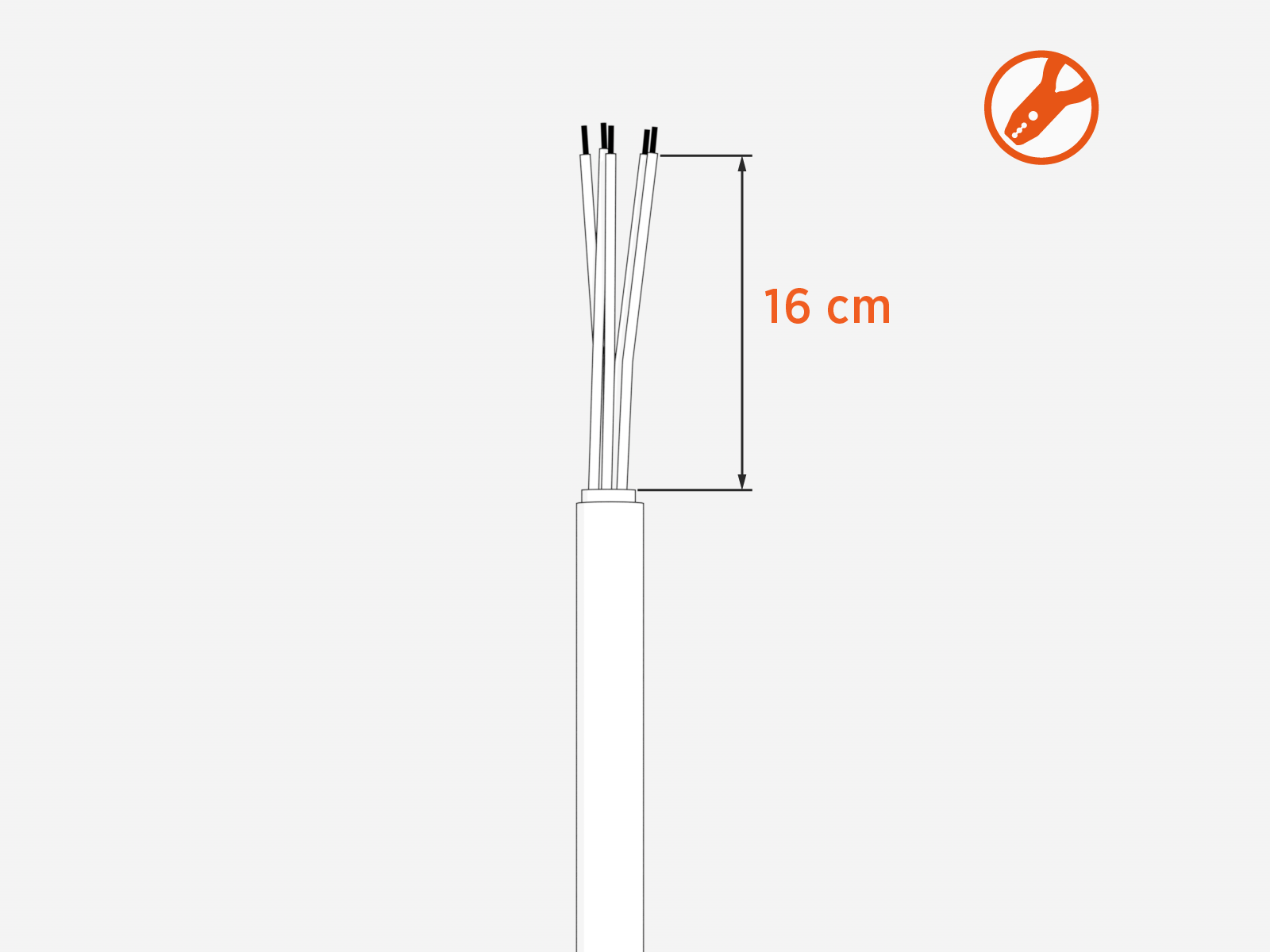
Strip 16 cm of the black outer wire cover.
-
Strip the wires 15 mm (0.6 in).
Use the label on the back plate as a guide for strip length.
.") Cut wires straight across at 90° and not at an angle.
Cut wires straight across at 90° and not at an angle.
-
Install the cable gland on the left-most opening on the bottom or back of the backplate.
Pull the wiring through the opening.
Tighten the cable gland nut to secure the wiring.
If wiring from the back, install the cable gland in the left-most opening on the back of the backplate instead of the bottom.
-
Insert the remaining fasteners into the mounting holes located in the backplate terminal block area to secure the backplate:
-
For wood mounting, use the two remaining 6 mm (1/4 in) 51 mm (2 in) lag screws that were provided.
-
For masonry or concrete mounting, use two masonry screws in the anchors (not provided).
-
If installing the station on a pedestal, use a T25 screwdriver to secure the station to the pedestal.
-
