Optional Energy Management Settings
ChargePoint Flex Plus charging station supports the following energy management solutions:
-
Shunt Trip
-
Current Dial
-
Smart Meter
-
Ethernet
-
Current Transformers
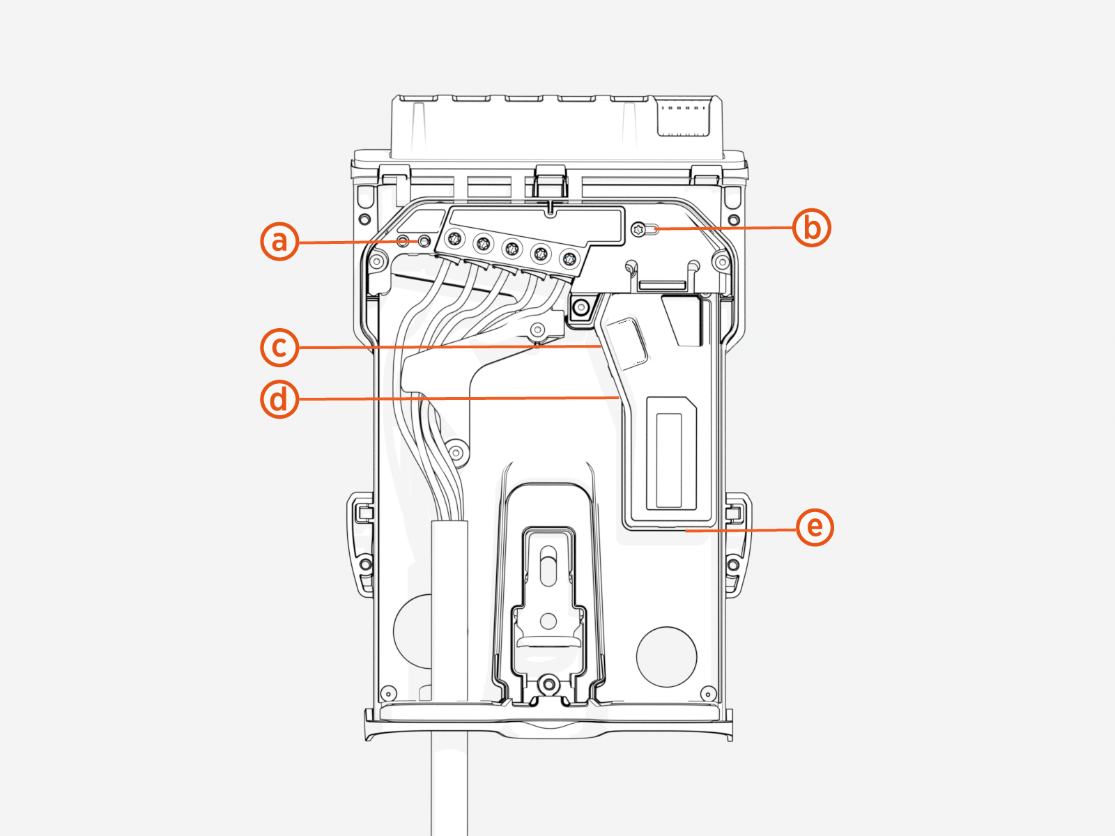
Shunt Trip Wire
If local regulations require that the charging station be connected to an RCBO![]() Residual Current Breaker with Overload Protection with shunt trip capability, use a 4.5 mm flat blade screwdriver to connect the shunt trip wire.
Residual Current Breaker with Overload Protection with shunt trip capability, use a 4.5 mm flat blade screwdriver to connect the shunt trip wire.
|
Label |
Meaning |
Notes |
|---|---|---|
|
L1 |
L1 connection to shunt trip |
Connect to external shunt trip line connection if shunt trip action is required on detection of DC leakage fault. |
|
N |
Neutral connection to shunt trip |
Connect to external shunt trip Neutral if shunt trip action is required on detection of DC leakage fault. |
-
Shunt trip must be rated to 230 VAC (L-N) - do not use DC input shunt trip.
-
Use wire strippers to remove 6-7 mm of wire insulation for installation into back plate shunt trip connector.
-
Acceptable wire sizes are 0.5-2.5 mm2
Smart Meter Functionality
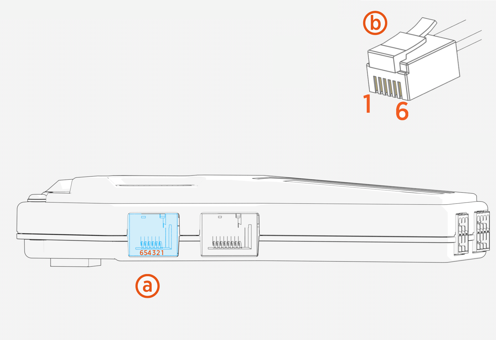
Local regulations may require smart meter functionality. The RJ12 connector is dedicated for smart metering functions. Determine your smart meter type and adjust J1 and J2 jumpers accordingly.
After connecting your smart meter to the RJ12 socket, configure load management settings in the ChargePoint Installer app.
|
Pin/Function |
Linky |
P1/DSMR |
EnWG |
MODBUS RS-485 |
MODBUS RS-232 |
|
1 |
NC |
+5V |
NC |
NC |
NC |
|
2 |
NC |
Data Request |
NC |
NC |
NC |
|
3 |
Linky 1 |
Data GND |
Contact 1 |
RS-485 B |
|
|
4 |
NC |
NC |
NC |
NC |
NC |
|
5 |
Linky 2 |
Data Line |
Contact 2 |
RS-485 A |
Data In |
|
6 |
NC |
Power GND |
NC |
NC |
-
Smart meter socket with pin orientation
-
Connector at the end of the cable with pin orientation
Applicable utility or regulatory requirements may mandate smart meter functionality.
| PIN | Connector | PIN | Connector |
|---|---|---|---|
| A1 | Linky1 | B1 | German_EnWG |
| A2 | Linky2 | B2 | EnWg_RTN |
| A3 | RS_232_TX | B3 | RS_232_RX |
| A4 | MODBUS_RS485_B | B4 | MODBUS_RS485_A |
| A5 | DSMR_Data_Request | B5 | DSMR_5VP0 |
| A6 | DSMR_Data | B6 | DSMR_GND |
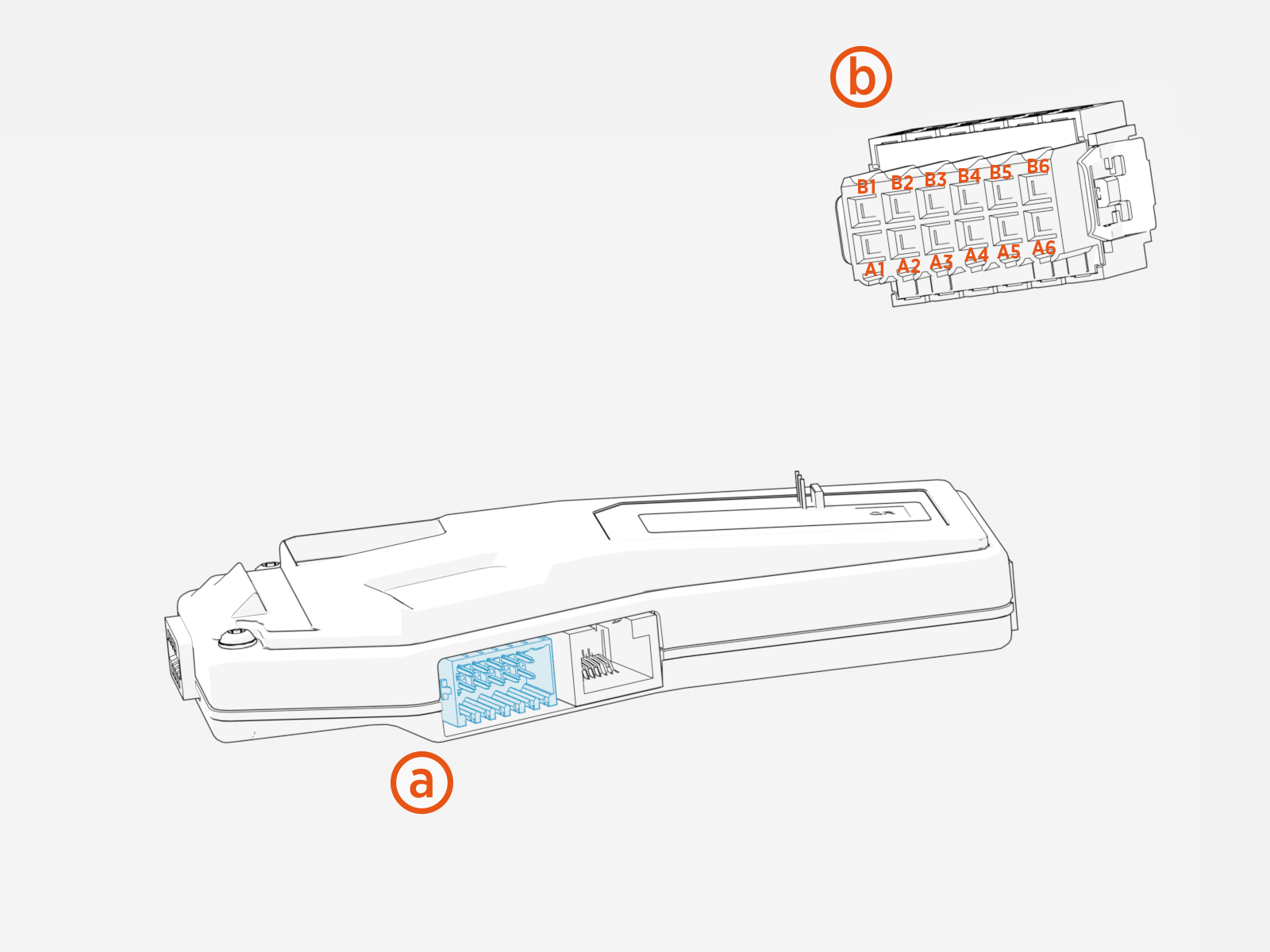
Below is the view of the connector from the side where the wires plug in.
After connecting your smart meter to the socket, configure load management settings in the ChargePoint Installer app.
Ethernet
Ethernet can be used to connect the charging station to a supported smart meter via MODBUS TCP/IP using an Ethernet RJ45 port. Ensure the meter is plugged into the same Local Area Network (LAN![]() Local Area Network) as the charging station and note the meter’s IP address for configuration. For correct operation of Dynamic Load Management (DLM
Local Area Network) as the charging station and note the meter’s IP address for configuration. For correct operation of Dynamic Load Management (DLM![]() Dynamic Load Management), configure the connection and settings in the ChargePointInstaller app.
Dynamic Load Management), configure the connection and settings in the ChargePointInstaller app.
|
Meter |
Connection Method |
|---|---|
|
Siemens PAC2200 |
MODBUS TCP via Ethernet RJ45 Port |
Current Transformers (CT)
Local regulations may require that you connect one or more CTs. The CT has a directional arrow in the middle of the core. This should be installed on the conductor pointing in the same directional flow of the current. Use the ChargePoint Installer app to configure load management settings.
Use the included connector to connect external CTs.
Insert the plug into the CT connector shown below.
-
CT socket with pin orientation
-
CT connector at the end of the cable with pin orientation
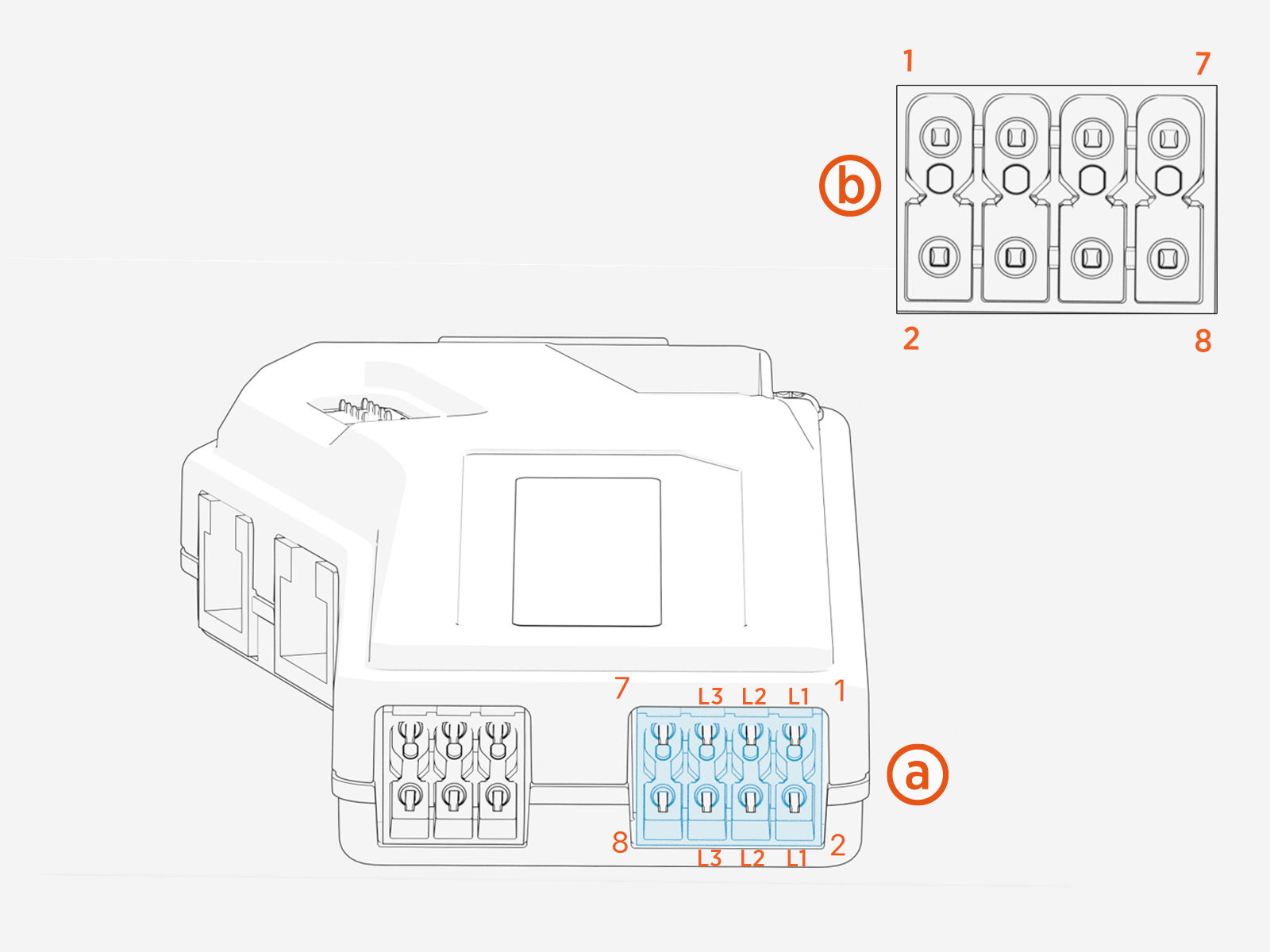
|
Pin |
Connection |
|---|---|
|
1 |
CT1 |
| 2 | CT1 |
| 3 | CT2 |
| 4 | CT2 |
| 5 | CT3 |
| 6 | CT3 |
The expected configuration is CTs with a current of 100 A and output voltage of 333 mV (burden resistor included).
For correct operation of DLM![]() Dynamic Load Management (Dynamic Load Management), use the ChargePoint Installer app to configure the station.
Dynamic Load Management (Dynamic Load Management), use the ChargePoint Installer app to configure the station.

