Wire the Charging Station
Read the following details carefully before wiring the AC terminals.
| Label | Meaning |
|---|---|
|
N |
Neutral (single phase or three phase grid connection) |
|
L1 |
Line 1 (single phase or three phase grid connection) |
|
L2 |
Line 2 (only for three phase connection, leave unconnected if single phase) |
|
L3 |
Line 3 (only for three phase connection, leave unconnected if single phase) |
|
PE/GND |
Protective Earth/Ground (single phase or three phase grid connection) |
Torque Guidelines
Follow these guidelines when torquing wires.
| Wire size | Torque value |
|---|---|
|
2.5 mm2 |
2.26 Nm (20 in-lb) |
|
4 mm2 |
2.26 Nm (20 in-lb) |
|
6 mm2 |
2.82 Nm (25 in-lb) |
|
10 mm2 |
4.0 Nm (35 in-lb) |
|
16 mm2 |
4.0 Nm (35 in-lb) |
Connect AC Terminal Input Wires
Complete the following steps to connect AC terminal input wires:
-
Wrap the PE/GND
 Ground wire around the wire guide and insert it into the PE/GND Ground terminal.
Set the T20 torque value to one that is suitable for the wire being used, then tighten the screw on the PE/GND
Ground terminal to the torque limit. (See Torque Guidelines for more information.)
-
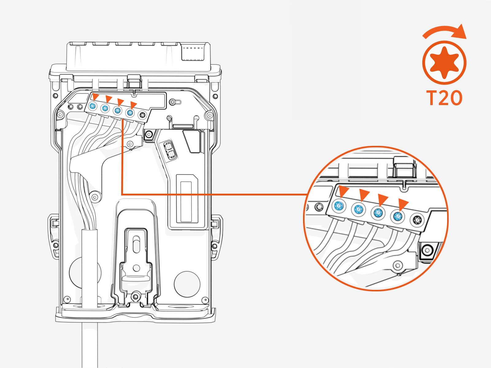
Wrap the N, L3, L2, and L1 wires around the wire guide and insert each wire into the terminal block.
Set the T20 torque value to one that is suitable for the wire being used, then tighten the screw on each of the four incoming wire terminals to the torque limit. (See Torque Guidelines for more information.)

-
Ensure all of the wires are tucked underneath the wire guide.

-
Adjust the current rating.
ChargePoint Flex Plus charging stations must be connected to a dedicated circuit breaker.
Use a T20 screwdriver to adjust the current dial (a).
When configuring the station using the Installer app, the breaker value selected by the dial will be displayed in the app for reference. However, this value is read‑only and cannot be adjusted through the app.
The charging station will be limited to this maximum current per phase, regardless of the charging station configuration.
Current Dial Values
Position
Amperage
Recommended Upstream Breaker 32 A
32 A (set in factory)
40 A 25 A
25 A
32 A 20 A
20 A
25 A 16 A
16 A
20 A 12 A
12 A
16 A 8 A
8 A
10 A X
Reserved, defaults to 8 A
10 A Y
Reserved, defaults to 8 A
10 A Z
Reserved, defaults to 8 A
10 A
If you choose to use a wired Ethernet connection to connect the charging station to your home, connect the RJ45 connector to the station. Configure the details in the ChargePoint Installer app.
If Ethernet is being used to connect to a smart meter, refer to the Ethernet section for more details.
Close the Backplate
Complete the following steps to close the backplate:
-
Ensure that the connections are secure.
-
Make sure the current dial has been set correctly.
-
Using a T20 screwdriver tighten all five screws to attach the backplate cover.

-
Torque each of the five screws to 0.5 Nm (4.5 in-lb).
