Head Assembly Replacement
Listed below are the instructions for replacing the head assembly.
Ordering Information and Shipping Specifications
| Output Type | Model | Weight | Dimensions |
|---|---|---|---|
| Single Output (non-gateway) | CT4010-HD | 25 lbs | 27” x 20” x 11.75” |
| Single Output (gateway) | CT4010-HD-GW | 25 lbs | 27” x 20” x 11.75” |
| Dual Output (non-gateway) | CT4020-HD | 31 lbs | 27” x 20” x 11.75” |
| Dual Output (gateway) | CT4020-HD-GW | 31 lbs | 27” x 20” x 11.75” |
| Dual Output (non-gateway) | CT4025-HD | 35 lbs | 27” x 20” x 11.75” |
| Dual Output (gateway) | CT4025-HD-GW | 35 lbs | 27” x 20” x 11.75” |
Inspect the Box for Contents
|
|
|
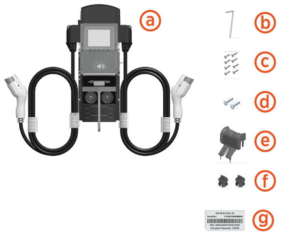
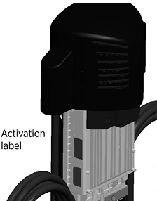
Keep the spare activation label. It contains important information that you must provide to allow the new head assembly to be activated on ChargePoint. A duplicate label is attached to the head assembly.
Gateway Stations Only
The shipping box also includes an envelope containing a SIM card and installation instructions. When replacing an existing gateway head assembly, leave the SIM card in the existing head assembly when returning it to ChargePoint.
|
|
|

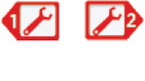
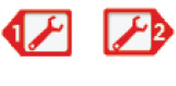
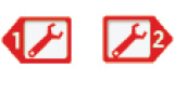
Depending on your ordering option, the head assembly may have only one charging cable.
Required Tools and Materials
|
|
Wire stripper |
|
#2 Philips screwdriver |
|
|
Needle nose pliers |
|
ChargePoint installer login credentials |
|
|
Smartphone with: Camera and Internet connectivity |
Remove the Existing Head Assembly
To remove the existing head assembly, follow the steps below:
-
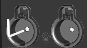
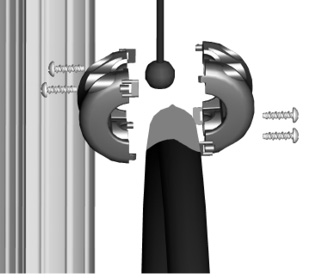
Disconnect the existing charge cables. If the charge cables are attached to the ropes using bracket type clamps (shown below), remove these clamps by loosening the four screws using a Phillips screwdriver. If the charge cables are attached using spherical clamps, disconnect these clamps by inserting the supplied service tool into the top of the clamp and rotating 1/4 turn counter-clockwise.
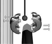 Bracket clamps
 Spherical clamps
-
With the station powered on, scan your ChargePoint card, then remove the charging plug(s) from the holster(s).
You must scan an activated ChargePoint card to unlock the holster(s) and remove the charging plug(s). -
Disconnect the station’s power at the electrical panel.
-
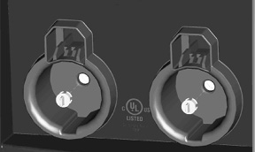
Use pliers to remove the rubber plug(s), located inside the holster(s).
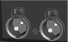

-
Open the shipping box for the new head
assembly and remove the L-wrench from the side of the new head assembly (illustrated on the previous page). Use this L-wrench to loosen the security set screw(s) located inside the holster(s).
TIP: After removing the L-wrench from the new head assembly, close the shipping box—you can use the top of the box to support the removed head assembly (as described in Step 10). -
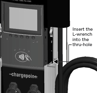
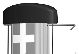
Raise the head assembly high enough to access the terminal block. To hold the head assembly in the raised position, insert the L-wrench into the thru-hole on the side of the head assembly. This hole is located on the right side of the head assembly and is marked with the screwdriver symbol.
-
Push the black tab on the terminal block to release the terminal block cover, then slide the cover up until it locks into the raised position.
-
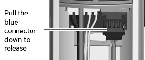
Disconnect the blue connector by pressing the side tabs while rocking the connector side to side and pulling downward.
-
Remove the L-wrench you inserted in Step 6 and lift the existing head assembly upwards to remove.
-
Place the removed head assembly on the shipping box to prevent damage when completing the next step.
-
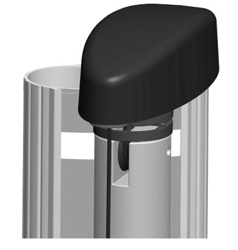
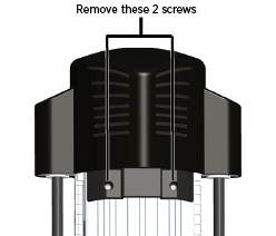
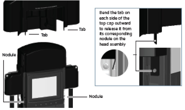
If the top cap is attached to the head assembly using screws, use a Phillips screwdriver, to remove the two screws from the back of the top cap.
OR

If the top cap is equipped with levered snaps, pull the tabs located at the back of the top cap. -
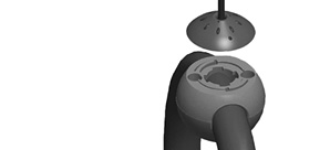
While using your fingers to release the top cap’s two retention tabs from their corresponding nodules (as shown below), pull the top cap upwards to remove.
-
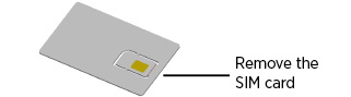
GATEWAY STATIONS ONLY :Ensure the SIM card remains inside the head assembly when returning the head assembly to ChargePoint.
Do not discard the SIM card - it must be included when returning the old head assembly to ChargePoint.

Install the New Head Assembly
To install the new head assembly, follow the steps below:
- Prepare the head assembly for mounting.
- GATEWAY STATIONS ONLY: Install the SIM card.
- Remove the SIM card (included in the shipping box) from its carrier by pushing it firmly.
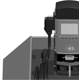
- Lift the rubber flap located on the left side of the head assembly, as shown.
- Insert the notched edge of the SIM card into the slot, with the notch facing upward. Slide it into the slot and push it FULLY into the slot until it clicks into place. Refer to the orientation instructions printed on the side of the head assembly.
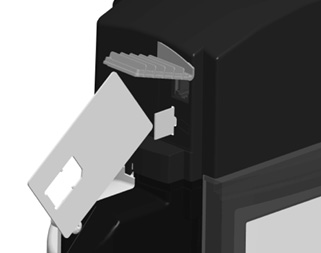 To push the SIM card into the slot, use the corner of the SIM card’s carrier, as shown.
- Reinstall the top cap.
- Place the top cap over the head assembly, ensuring correct alignment.
- If the station is equipped with a screw-type top cap, use a Phillips screwdriver to secure the top cap to the head assembly by inserting its two screws (extra screws are provided in the shipping box) into the back of the top cap and tightening to 20 in-lbs.
OR
If the station is equipped with a snap-type top cap, push the snaps located at the back of the top cap. - Slide head assembly into the body.
Slide the head assembly into the main body until it is stopped by the head assembly’s security tag.
Do not insert the charging connectors into the holsters until after you have powered up the station. Doing so causes the holsters to permanently lock.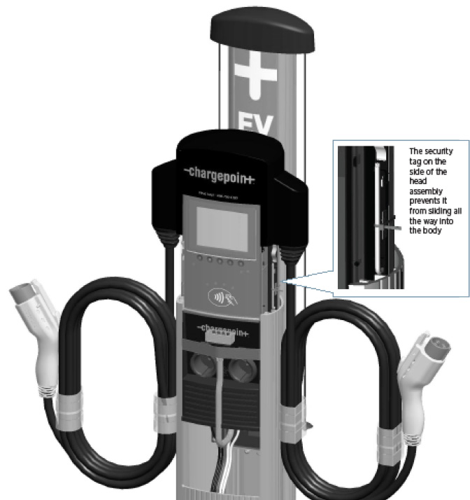
- Connect the head assembly.If replacing a head assembly on a dual port station that has been set up to operate from only one circuit, or on a station that operates at a current capacity lower than 30A per circuit, refer to the instructions provided in the Power Management Kit (ordered separately).
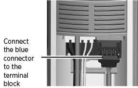
Pull to remove the yellow strap from the blue connector.
Connect the blue connector to the blue receptacle by the terminal block, ensuring it clicks into place and is fully seated.
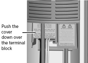
Push the cover down over the terminal block.
- Perform Station Setup Tasks.
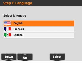
Power up the station. What you do next depends on what you see after the station powers up.
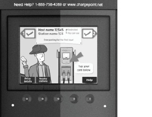
If you see a progress bar followed by the screen shown here, follow the on-screen instructions to complete the installation before proceeding to the next step. See below for details.
If you see this animation screen, check for errors. Re-install the cable clamps. To enable the optional Power Management features, refer to the instructions provided in the Power Management Kit (ordered separately).
 If the station does not power up, check that the head assembly’s blue rectangular connector is properly seated onto the terminal block.
About the Installation Wizard
The onscreen Installation Wizard walks you through the setup tasks and verifies the station is operating correctly.
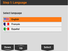
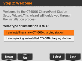
Choose this option and follow the on-screen instructions
- Secure the head assembly
Remove the L-wrench from the hole in the right side of the head assembly, then lower the head assembly. Ensure the head assembly is fully seated and that no gap exists between the bottom of the head assembly and the main body. The head assembly fits tightly and may require extra downward force to ensure it is fully seated.
Using the L-wrench, tighten the two security set screws, located inside the
holsters, to approximately 25 to 30 in-lbs (2.8 to 3.4 Nm).Cover each screw using a rubber plug.
Insert the charging cables into their corresponding holsters.
- Install cable clamps.Do not unwrap the ropes until they are securely attached to the charging cable.
There are two types of cable clamps available for the CT4000. The type of clamp that is used depends on whether the end of the nylon rope in the cable management kit is equipped with a circular disc or a round bead:
If equipped with a circular disc, the cable clamps are spherical type.
If equipped with a round bead, cable clamps are bracket type.
In some cases, you may need to remove an existing pre-installed portion of a cable clamp from the charging cables before you can install the type of clamp that is supplied in the cable management kit. When doing so, you must install the new clamp at the exact same location as the removed clamp.After installing the cable clamps, unwrap the rope and check that the charging cable extends and retracts fully and smoothly.
To install spherical clamps:
-
Uncoil charging cable by gently extending it all the way out and away from the station. Rotate the plug as needed to remove any twist or kinks.
- Position the charging cable near the base of the station and locate the tape on the cable that marks the location where you must install the clamp.
- Insert a rubber shim into the bottom portion of each clamp. Ensure the top portion of the cable clamp is oriented correctly on the top side of the charge cable. Tighten screws to 20 in-lbs (2.3 Nm).
- Align the knot bearing on each rope to its corresponding mating feature on the cable clamp. Turn the knot bearing clockwise approximately 1/4 turn. You may need to push down while turning the knot bearing.
.jpg)
To install bracket clamps:
- Uncoil charging cable by gently extending it all the way out and away from the station. Rotate the plug as needed to remove any twist or kinks.
- Position the charging cable near the base of the station and locate the tape on the cable that marks the location where you must install the clamp.
- Locate the bead at the end of the retractor rope.
- Hold the charging cable with the marked tape positioned under the retractor top. Ensure the charging cable does not touch the ground when fully retracted.
- Insert the bead inside the clamp, then snap the opposite side of the clamp into place.
- Secure the two sides of the clamp together by inserting the rubber shim and the four screws, then tightening the screws securely using a Phillips screwdriver.
You have now finished the physical installation of the new CT4000 head assembly and are ready to prepare the new head assembly for activation on ChargePoint.
Preparing the new head assembly for activation on ChargePoint involves filling in the double-sided form provided on the next two pages, detaching the sheet from this document, and providing it to the person responsible for activating the station on ChargePoint. After doing so, the installation of the CT4000 charging station’s new head assembly is complete.
Prepare for Activation
This section outlines the necessary tasks and checks to be performed prior to activation.
Record information from the old head assembly
Write down the following information from the old head assembly’s activation label. This label is located on the right side of the head assembly, as shown.
Activation Labels
OLD | Enter Mac Address here: __________________________ |
Enter Activation Password here: __________________________ |
Record information from the new head assembly.
Place the spare activation label for the new head assembly (included in the shipping box) here:
NEW |
|

Head Swap Procedure
After completing the checklist on the following page, tear out this page and provide it to the person responsible for activating ChargePoint stations.
Post-Installation Checklist
Before leaving the installation site, complete this checklist. Then tear out this page and give it to the person responsible for activating the station.
þ | Check each box below to confirm that the task has been completed. |
o | The two security screws inside the holster plugs on the head assembly are tightened and the rubber plugs are in place. |
o | Cable clamp halves are re-installed and charging cables operate smoothly through full extension and retraction. |
o | The station has adequate communications signal(s). |
o | Voltages at all power plates have been verified with a solenoid type voltmeter (such as a Wiggy):
|
o | If Power Share Jumpers are installed:
|
o | If Power Select is applied:
|
o | If you have installed a station that runs the Installation Wizard upon power up, ensure that you have completed all steps of the Installation Wizard and that the station currently displays the animation screen. |
o | If you have installed a station that does not run the Installation Wizard upon power up, ensure that you have installed the cable clamps and verified that no faults are detected. |
o | When starting a charging session using your ChargePoint card, the station displays no error codes or warning lights, and both holsters unlock and lock. |
o | Station information for both the old head assembly and new head assembly has been recorded on the opposite page. |
Troubleshooting
Check the Station’s Display
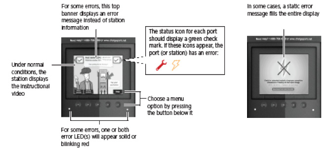
When the station is powered on and the Installation Wizard has been completed, you should see:
- The instructional video, and no error messages.
- The status icon for each port displaying a green check mark.
- Both error LEDS are extinguished (for some errors, one or both error LEDs are solid or blinking red).
Display Station Codes
To check the station for errors anytime after initial power up, follow these steps to display station codes.
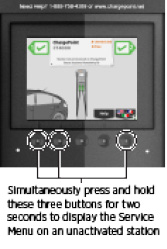
Display the station’s Service Menu:
- if the station is not activated on ChargePoint, simultaneously press and hold the two leftmost buttons and the rightmost button for two seconds.
- if the station is activated on ChargePoint, scan your ChargePoint Service card
Press the station button immediately below the HELP menu option.
Press the station button immediately below the DOWN menu option to highlight Station Codes.
Press SELECT.
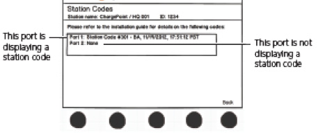
If you see a station code, you must resolve or report the error before leaving the installation site. Station codes are described on the following pages.
Description of Station Codes
If you see a station code (see the previous page for details on how to display station codes), you must resolve or report the error before leaving the installation site.
Code | Symptom | Possible cause(s) | Recommended Action(s) |
In most cases, a driver can resolve the following station codes that begin with the digit “1”: | |||
101- Over Current Detection |
| During charging, the vehicle attempted to draw more power than allowed. The station stops delivering power to the vehicle. | Can indicate faulty wiring in the vehicle. End the session by inserting the station’s plug back into its holster, then restart the session. If the error persists, call ChargePoint Customer Support. |
102- Ventilation Requested |
| Vehicle requires ventilated charging which is not supported by the station. The station stops delivering power to the vehicle. | Driver will be unable to use the station to charge their type of vehicle. Call the vehicle manufacturer. |
103- Soft Ground Fault |
| During charging, the station detected a ground fault. The station stops delivering power to the vehicle, but continues to retry every 30 seconds. | End the session by inserting the station’s plug back into its holster, then restart the session. If the error persists, call ChargePoint Customer Support. |
104- Immediate Ground Fault |
| On initial plug-in, the station detected a ground fault. The station stops delivering power to the vehicle. | End the charging session by inserting the station’s plug back into its holster, then restart the session. If the error persists, call ChargePoint Customer Support. |
In most cases, an electrician can resolve the following station codes that begin with the digit “2”: | |||
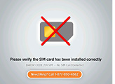
201-SIM
|
| SIM Not Detected The SIM is either not installed or is incorrectly installed and the station can not communicate with the ChargePoint network. | Disconnect power and install (or re-install) the SIM card. If the error persists, call ChargePoint Customer Support. |
202-EF |
| Earth Fault The station has detected a poor ground connection and the station is not operational. | Disconnect power and check that the station is properly grounded. After ensuring the station is properly grounded, reconnect power. If the error persists, try unplugging the head assembly and plugging it back in. If the error continues to persist, call ChargePoint Customer Support. |
The banner between the port icons displays “STATION NOT ACTIVATED ON CHARGEPOINT - GRACE SESSIONS REMAINING (N).” When all grace sessions have been used:
| Station not activated The station can be used to charge for the specified number of remaining grace sessions. When all grace sessions have been used, the station is not operational. | Arrange for the station to be activated on ChargePoint. | |
Before activation: The banner between the port icons displays NO GATEWAY WITHIN RANGE. After activation: All you will see is the code listed on Help > Station Codes. | Non-Gateway Not Paired The station is set up to communicate with a gateway station that is either not within range, or is not powered on. | Verify that the gateway station is powered on and located within 150 feet line of sight (no obstructions). If the error persists after these requirements are met, call ChargePoint Customer Support. | |
Before activation: The banner between the port icons displays NETWORK SIGNAL NOT DETECTED. After activation: All you will see is the code listed on Help > Station Codes. | Unknown Network Signal The gateway station is unable to establish a network connection on AT&T/Verizon (US) or Rogers (Canada). | Ensure the station is receiving an adequate signal strength from the cellular network. To do so, display the Service menu*, then:
If the signal strength is either weak (D) or not available for both CDMA and GSM, arrange for cellular repeaters to be installed near the installation site. If the error persists when the station shows a strong network signal, call ChargePoint Customer Support at 1-877-850-4562. *To display the station’s Service Menu, scan your ChargePoint Service card (if the station is activated) or, if the station is not activated, press the three station buttons. | |
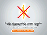
Before activation:
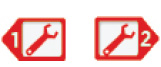
After activation: You will see the code listed on Help > Station Codes and the port status icons will show:
or
| Floating Line Connection The voltage of an AC input line has fallen below 80 volts AC relative to ground. Even if the line to line voltage measures nominally 208 or 240 volts, the voltage of each line must be greater than 80 volts when measured to ground. The two most common causes of a Power Line Fault are:
| Correct any faulty connections. Verify that the station is connected to a system with its neutral properly grounded according to NEC
| |
ChargePoint Support may need to resolve the following station codes that begin with the digit 3: | |||
| Breakaway Fault | Call ChargePoint Customer Support at 1-877-850-4562 to arrange to have the station replaced. | |
302-GST |
or
| GFCI | End the session by inserting the station’s plug back into its holster, then restart the session. If the error persists, call ChargePoint Customer Support at 1-877-850-4562. |
303-RSC |
or
| Relay Stuck Closed When attempting to end a charging session, the relay stays closed. Although the driver can return the station’s plug to its holster, the station doesn’t end the session. Therefore, a new session can not be started. | Call ChargePoint Customer Support at 1-877-850-4562 to arrange to have the station replaced or repaired. |
305-LCO |
| Pilot Unreachable The station is out of service. | Disconnect and reconnect power. If the error persists, call ChargePoint Customer Support at 1-877-850-4562 to arrange to have the station replaced or repaired. |
306-BF |
| Boot Fault | Disconnect and reconnect power. If the error persists, call ChargePoint Customer Support at 1-877-850-4562 to arrange to have the station replaced or repaired. |
307-HE |
| Hardware Error The station is out of service. | Disconnect and reconnect power. If the error persists, call ChargePoint Customer Support at 1-877-850-4562 to arrange to have the station replaced or repaired. |


Charging Cable Doesn’t Move Freely
If the charging cable does not extend or retract fully and smoothly, it is likely that it’s rope has come off the pulley and you must re-position it.
You will need:
L-wrench
Follow these steps:
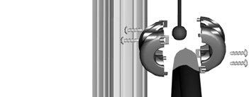
Using the L-wrench, loosen the set screws on each side of the retractor below the top cap.
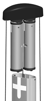
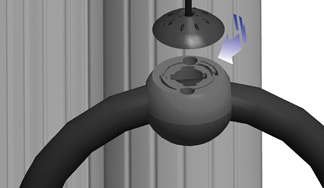
Each rope is attached to a weight that sits on a shelf. Pull the weight shelf up by pulling the rope located in the middle of the top cap.

Rotate the top cap so the weight controlling the rope that doesn’t move freely is facing towards you.
Inspect the rope to ensure it is properly aligned onto the pulley.
Carefully lower the weight back into the retractor.
- Rotate the topi cap back into position and re-tighten the set screws to about 10 in-lbs. Ensure the rope is properly aligned onto the pulley.