Replace Power Plate
Listed below are the instructions for replacing the power plate.
Do not discard the part you are replacing. Use the new Field Replaceable Unit (FRU![]() Field Replaceable Unit) packaging to return all removed parts to ChargePoint.
Field Replaceable Unit) packaging to return all removed parts to ChargePoint.
For assistance, go to chargepoint.com/support and contact technical support using the appropriate region-specific number.
Required Tools and Materials
The following are the tools and equipment required for replacing power plates.
-
ChargePoint card or smartphone with ChargePoint app installed
-
ChargePoint installer login credentials
-
T25 tamper-resistant Torx driver
-
3/8 in hex nut driver or 10 mm 6-point socket driver
-
Socket extension
-
Needle nose pliers
-
Felt tip pen or tape
-
Headlamp
-
Safety glasses
-
Blanket, cardboard, or other padding
Install the CT4000 Power Plate
To install a power plate, perform the steps below:
-
Use your ChargePoint card or the mobile app to start a charging session, unlock the charging cables, and set them gently down.
-
Disconnect the power to the CT4000 at the service panel.
RISK OF SHOCK
Before performing any procedure, the technician must disconnect the power to the charging station at the service panel. Follow local code to de-energize the applicable circuit and lockout/tagout the upstream breaker before proceeding. Use a multimeter and check that the power is off. Keep power off for the circuit until all cover panels are correctly reinstalled and the work is complete.
FAILURE TO FOLLOW THESE INSTRUCTIONS CAN RESULT IN SERIOUS INJURY, LOSS OF LIFE, OR PROPERTY DAMAGE. -
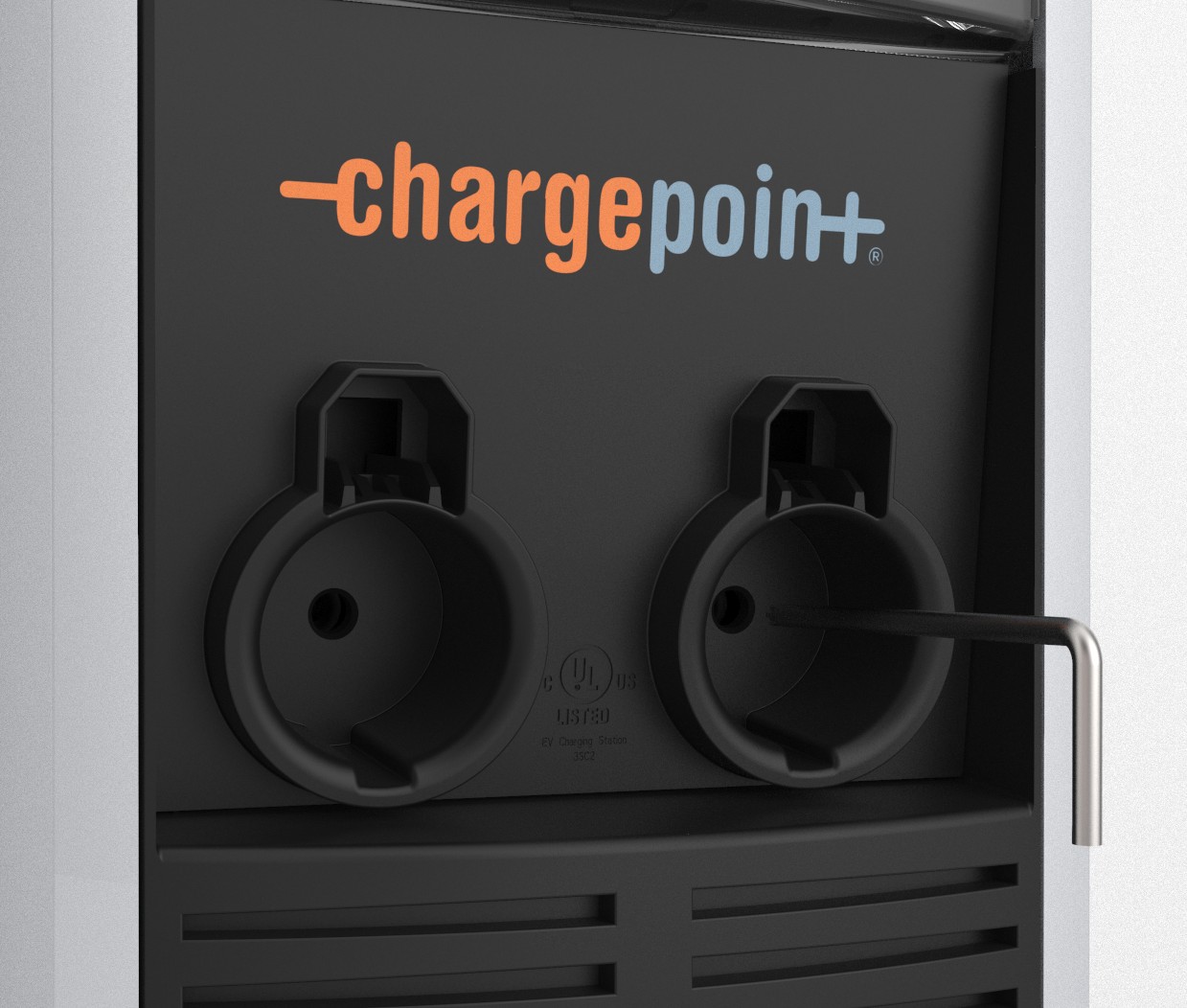
Use needle nose pliers to remove the rubber plugs from inside the holsters (a). Save these for reuse.

-
Use a T25 tamper-proof Torx driver to loosen, but not remove, the security screws inside the holsters (b).
-
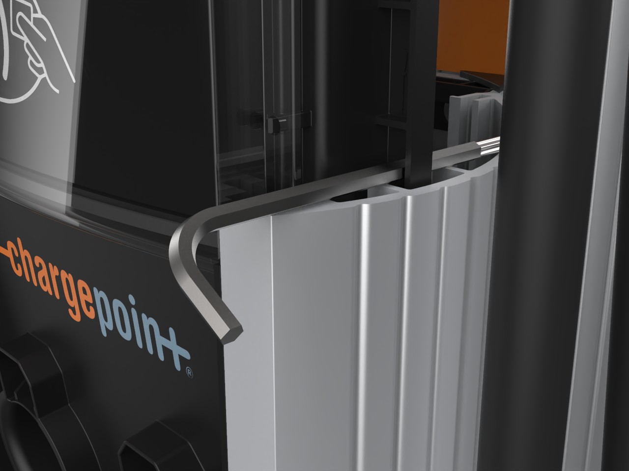
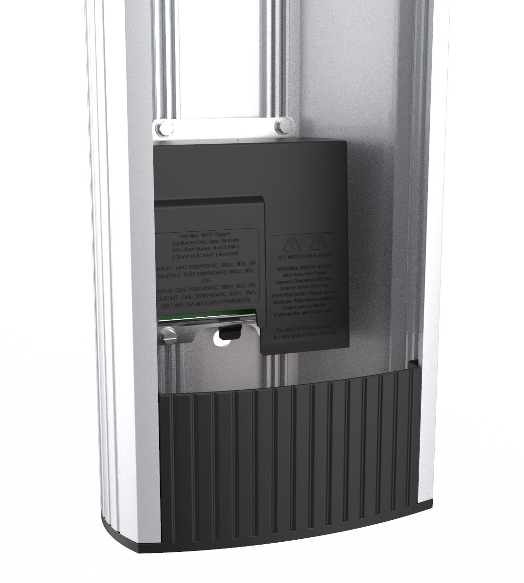
Raise the head assembly high enough to access the terminal block. Insert a T25 Torx driver into the hole (c) on the side of the side of the head assembly to hold the head assembly in the raised position.
-
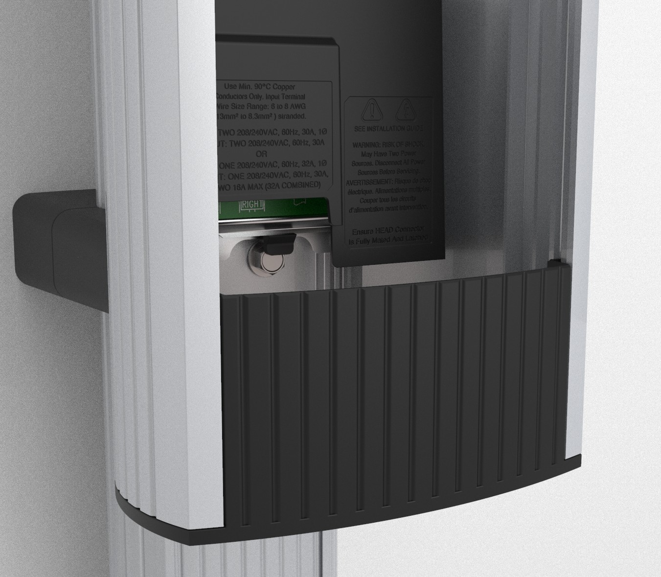
Push the black tab on the power plate (d) to release the power plate shroud, then slide the shroud up until it locks into the raised position.
-
Disconnect the blue connector by pressing the side tabs while rocking the connector side to side and pulling downward.
Inspect the blue connector for signs of overheating. If signs of overheating are evident, contact ChargePoint Support. Visit chargepoint.com/support to find your region’s technical support number. The head assembly might be damaged.

-
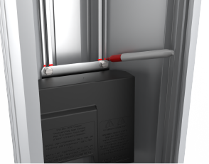
Remove the T25 Torx driver and lift the existing head assembly upward to remove. Place the head assembly on a blanket or other soft surface to prevent damage while completing this procedure.
-
Remove the wires from the terminal block and move them out of the way.
-
Use a 3/8 in hex nut driver or a 10 mm 6-point socket driver to remove the lower screws (f) holding the power plate in the housing.
 When securing the new power plate, torque these screws to 4.5 Nm (40 in-lb).
 -
Lower the black plastic power plate shroud.
-
Use a felt tipped pen (g) or a piece of tape to mark the position of the power plate inside the housing.
-
Use a 3/8 in hex nut driver or a 10 mm 6-point socket driver to remove the upper screws (h) holding the power plate in the housing. When securing the new power plate, torque these screws to 4.5 Nm (40 in-lb).
-
Remove the power plate.
-
Reverse the above steps to install the new power plate and reinstall the head assembly.
Use the marks to align the new power plate in the same location as the previous power plate.Insert the AC wires in the same positions as they were in the original power plate, lowering the white levers on each terminal after inserting the wire. Perform a push-pull test to ensure the wires are secure.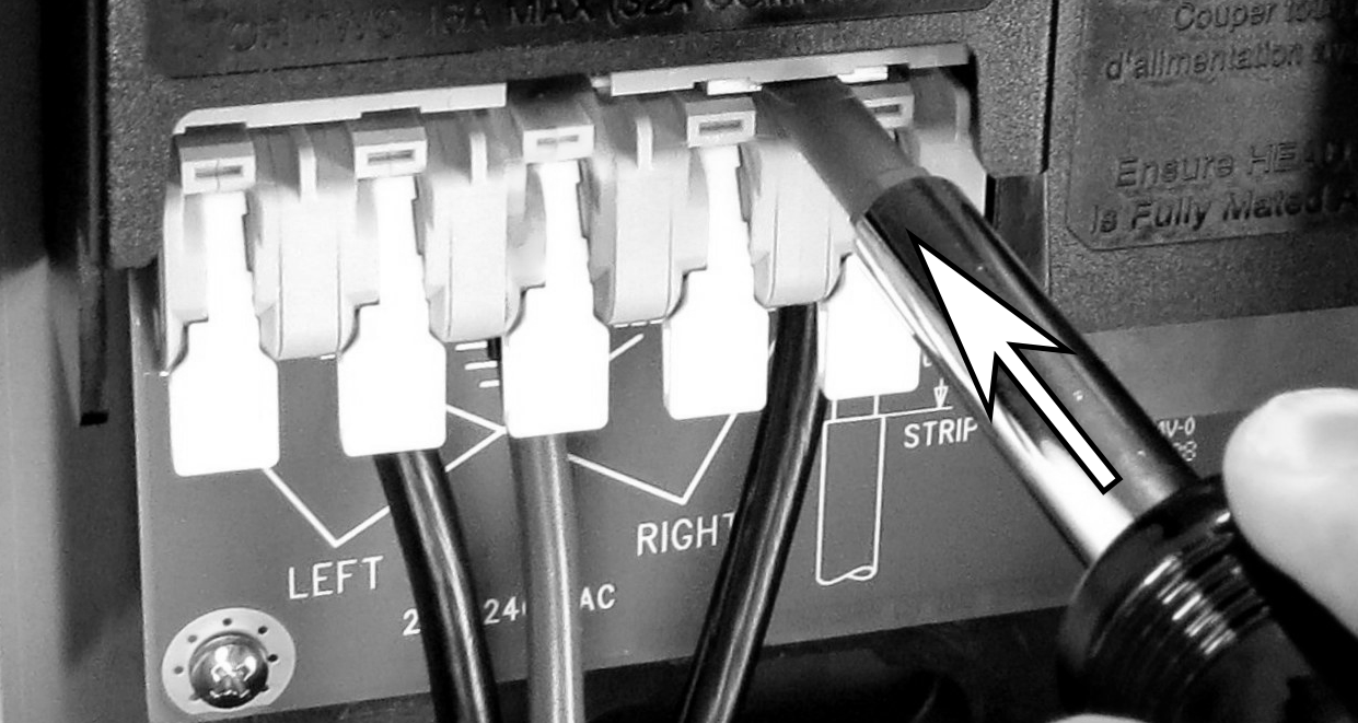
If a single circuit is feeding the CT4000, install the jumpers from the old power plate (i) in the terminal block in the new power plate. Make sure the jumpers are fully seated.
For wiring information, refer to the following Review Wiring Diagrams.

Review Wiring Diagrams
These wiring diagrams show wiring for installing a dual port CT4000 on a dual circuit. Two dedicated circuits are required, each with its own two-pole 40 A breaker, unless it is configured for operating at reduced power.
208 VAC, Three Phase Panel
-
L1
-
L2
-
L3
-
Neutral
-
Main breaker
-
Neutral bus
-
Ground bus
-
Left
-
Right
-
12 mm (0.5 in) wire strip length

240 VAC, Single Phase Panel
-
L1
-
L2
-
Neutral
-
Main breaker
-
Neutral bus
-
Ground bus
-
Left
-
Right
-
12 mm (0.5 in) wire strip length

