Install the SCE Box Base and Box Cover
-
Use a T25 Torx to remove the rodent guard L-brackets on each side of the station below the AC and DC wiring terminals.

-
Install the rear EMI
 Electromagnetic Interference shield:
-
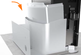
Position the rear EMI
Electromagnetic Interference shield (a) over the closed Power Module holder, the drain hose, and the cooling controller cover (b). Ensure the cutout on the long edge is on thes right side, leaving the sensor wire clear.If the top edge of the EMI
Electromagnetic Interference shield risks contact with the wiring below the cooling controller or the drain hose, pad the edge of the shield with electrical or duct tape to prevent abrasion. -
Use a T20 Torx to remove the two screws (c) that align with the top EMI
Electromagnetic Interference shield tabs. Discard the star washers beneath them, if present. -
Use isopropyl wipes to clean the frame grounding locations and both sides of the rear EMI
Electromagnetic Interference shield tabs. -
Use a T20 Torx to reinstall the top screws with an M5 flat washer from the installation kit to secure the top tabs of the shield on each side.
-
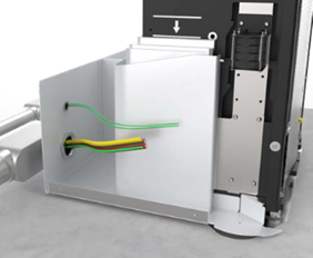
Use a T25 Torx, an M5 screw, and an M5 washer to attach the rear EMI
Electromagnetic Interference shield to each middle and bottom grounding location on the rear of the frame (d). Torque to 4 Nm (35 in-lbs).
-
-
Loosen the captive screws along the bottom edges of the SCE
Surface Conduit Entry to release the cover from the base. Set the cover aside. -
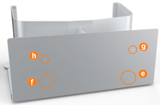
Based on the provided pilot holes, use a sheet metal drill bit to create the circle in the rear face of the box base for AC (e). Drill out the circle for DC only if the station will be paired (f).
-
If the station will have shunt trip wiring (g) or Ethernet (h), use a 45 mm (12/16 in) core bit to drill the hole(s) based on the provided pilot holes.
Ensure the locations of the shunt trip and Ethernet holes do not interfere with routing wireway elbows and conduit. Calculate height clearance for all wireways. -
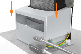
Position the SCE
Surface Conduit Entry box base around the back of the station. Be careful not to slide the bottom edge of the box base underneath the surface mount plate. The box base cannot be installed on the station if the lower rear cover panel is already installed.
 -
Install the lower rear cover panel inside the gap between the box base and the station:
-
Using two hands, one on each side of the lower rear panel, align the guide tabs on the lower rear panel to the matching slots on the Express 250.
-
Squeeze the sides of the panel inward to fit the tabs into place in the C-channel, inside the watertight gasket. Carefully push the panel down.
 The charging station has guide marks on the frame, to show initial and final cover locations.
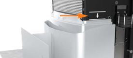
-
-
Use a T25 Torx to fasten the box base to the station with 4 screws on each side (8 total, included in the SCE
Surface Conduit Entry Kit). Torque to 4 Nm (35 in-lbs).
-
Install surface wireways between the service panel and the Express 250 box base.
-
Fasten elbows to the Express 250 box base and to the wireway using a code-approved sealing method.
-
Pull all wiring through the wireways into the box base.

-
Go to the sections in the Express 250 Installation Guide for wiring the AC conductors (and DC if pairing the station). Land all applicable wires (AC, shunt trip, DC, and Ethernet) per the installation instructions.
-
Slide the box cover over the box base.
-
Ensure the top corners of the box cover slide over the box base guide pegs.

-
By hand, tighten the two captive screws on each bottom side edge that fasten the cover to the base. Torque to 4 Nm (35.4 in-lbs).

-
Open the Power Module holders.
-
Install the right and left extrusions, aligning the cutouts over the edges of the SCE
Surface Conduit Entry box cover. SCE Surface Conduit Entry extrusions have five captive screws each (one bottom, two middle, two top). The bottom rear screw is not present. Fasten these captive screws as mentioned in the Installation Guide. For installation or servicing, SCE Surface Conduit Entry extrusions can be removed without removing the SCE Surface Conduit Entry or rear bottom panel. However, if the rear bottom panel must be removed, first remove the SCE Surface Conduit Entry cover and loosen the box base side screws.
Continue Normal Installation
-
Continue following the Express 250 Installation Guide to complete the rest of the station installation: install Power Modules, the front EMI
Electromagnetic Interference shield, and all other cover panels. -
When on-screen configuration prompts for either replacement or new installation, choose New.
-
Complete normal Express 250 pinpointing procedures through the end of the manual.
