Replace the Power Plate
Required Tools and Materials
|
|
Torx screwdriver (T25) |
|
|
Hex wrench (4 mm and 8 mm) L wrench included, combined with T25 Torx |


Remove the Head Assembly
Perform the following steps to remove the head assembly:
-
Use your ChargePoint card or the mobile app to start a charging session.
If the station does not have power, contact the station owner to learn when power will be available and discuss appropriate next steps.If you do not have a ChargePoint account, go to chargepoint.com/support, find your region's technical support number, and contact ChargePoint Support.
-
Unlock the charging cables, and set them gently down.

-
Disconnect the power to the CP6000 at the service panel.
Risk of shock
-
Before any procedure, the technician must disconnect the power.
-
Follow local code to de-energize the applicable circuit and lock out/tag out the disconnect before proceeding. Use a multimeter to test that power is off.
-
Keep power off until the top cap is correctly reinstalled and the work is complete.
Failure to follow these instructions can result in serious injury, loss of life, or property damage.
-
-
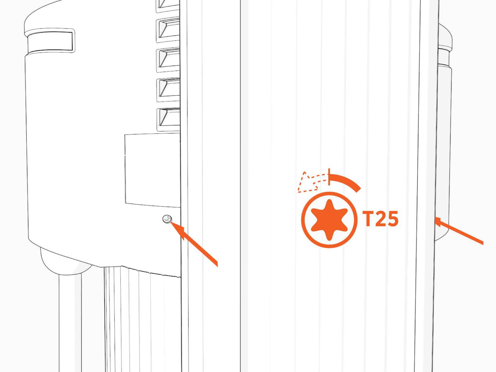
Use the L-wrench to loosen the two T25 screws securing the top cap.
-
Remove the top cap.

-
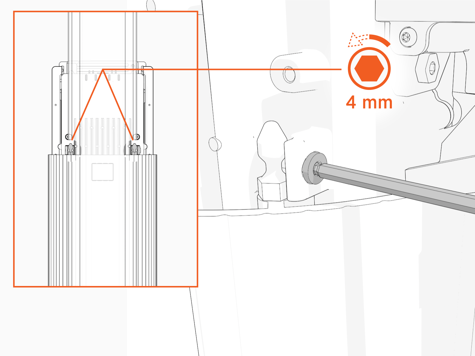
Use the L-wrench to loosen, but do not remove, the screws securing the head assembly.
-
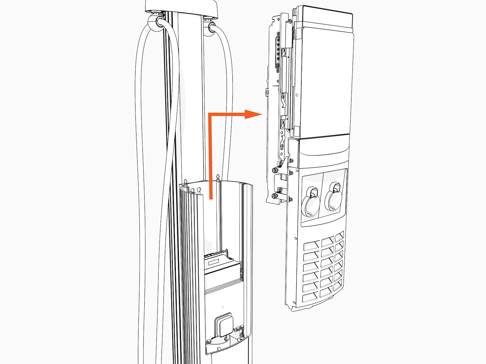
Lift the head assembly to remove it from the pedestal or wall mount enclosure. Place it gently face down on a padded surface.
Remove the Power Plate
To remove the power plate, perform the following steps:
Risk of shock
-
Before any procedure, the technician must disconnect the power.
-
Follow local code to de-energize the applicable circuit and lock out/tag out the disconnect before proceeding. Use a multimeter to test that power is off.
-
Keep power off until the top cap is correctly reinstalled and the work is complete.
Failure to follow these instructions can result in serious injury, loss of life, or property damage.
-
Before removing the power plate, disconnect the wiring as follows:
-
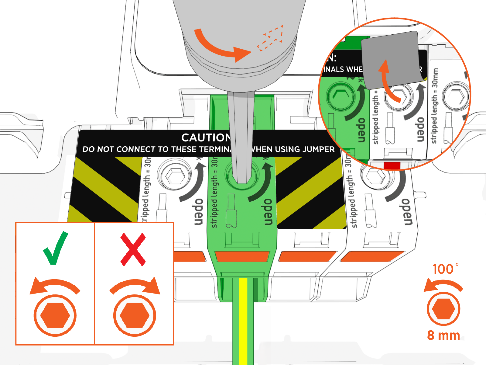
Insert an 8 mm (5/16 in) hex wrench and rotate it counterclockwise. You might need to lift the label flap to access the terminal block.
-
Hold the driver in place to keep the terminal open while removing the wire.
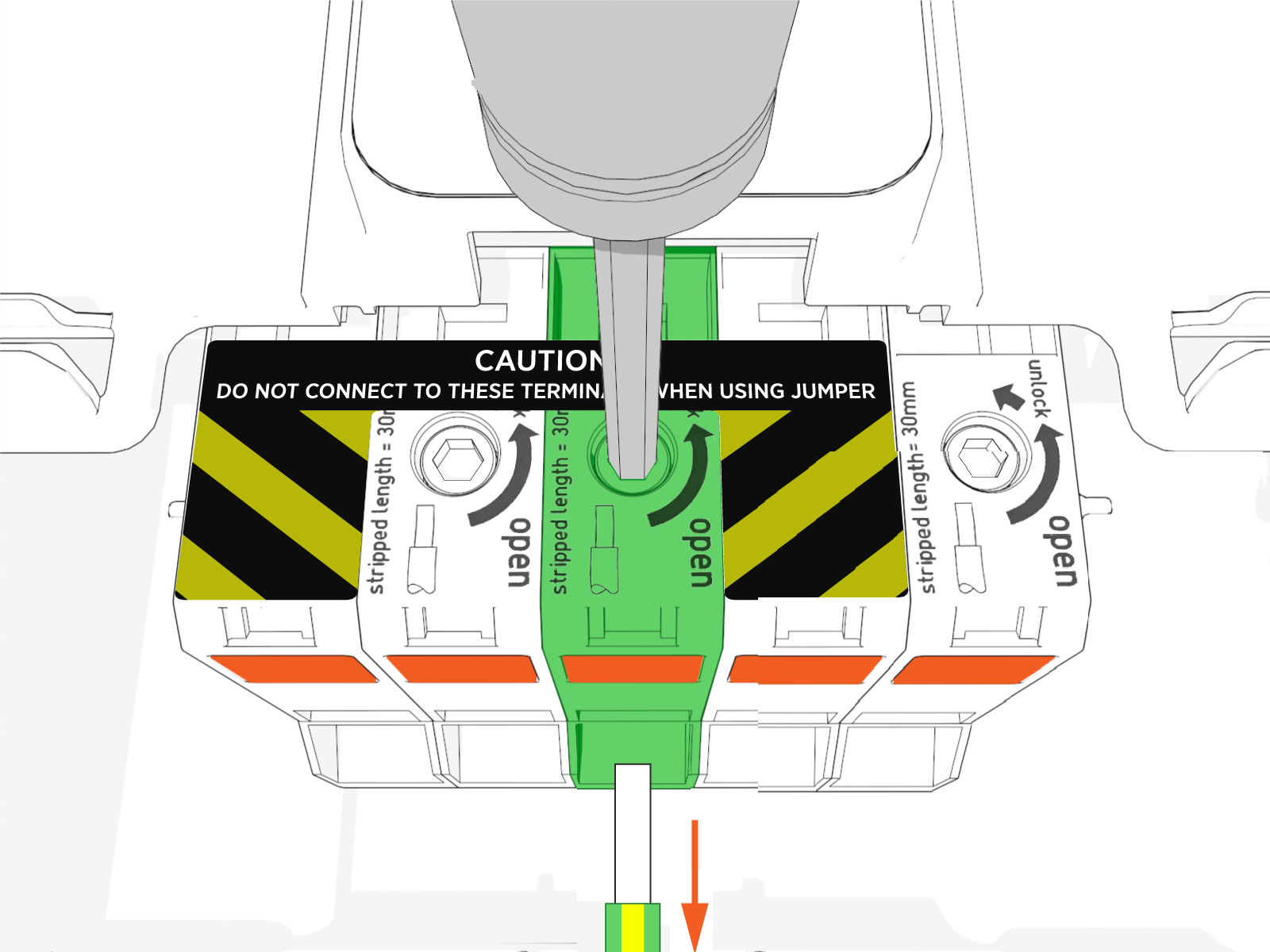
-
-
Using a T25 torque driver, loosen but do not remove screws securing the power plate.
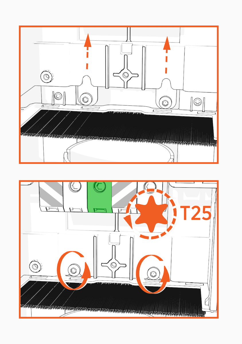
-
With the screws still in place, carefully lift the power plate upward to remove it from the metal bracket.
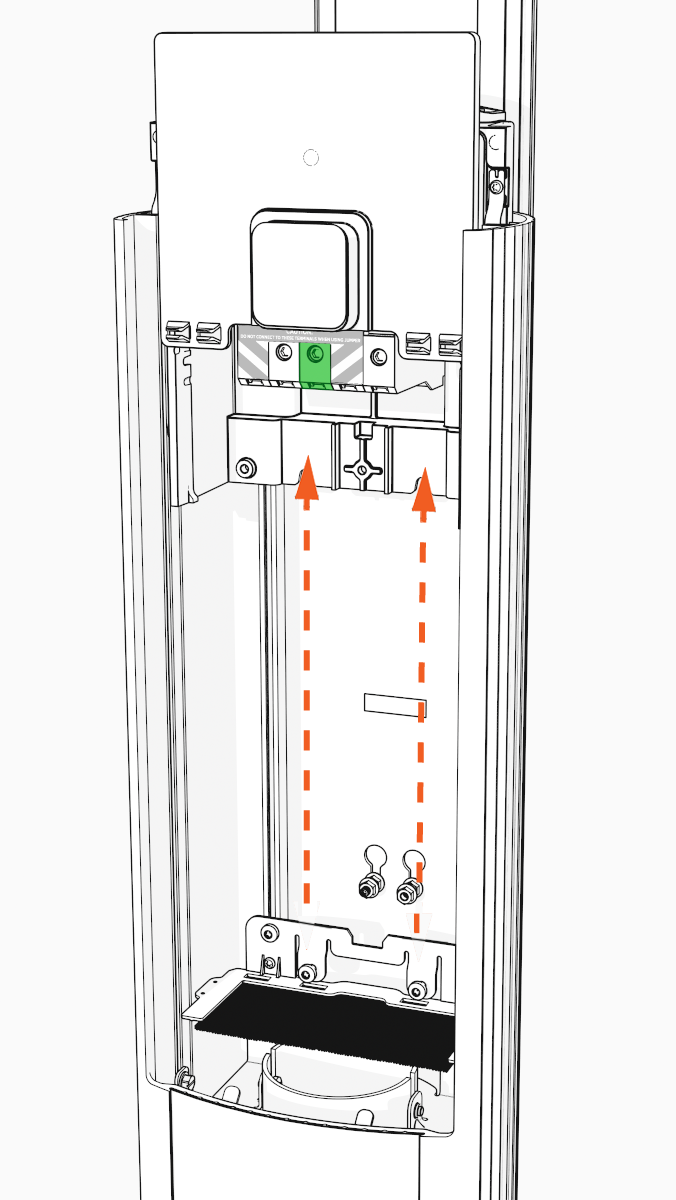 Avoid damaging the shunt trip cables when handling or removing the plate.
 -
Ensure the power plate is completely removed.
-
Verify that no components or cables are obstructed after removal.
Install the New Power Plate
Perform the following steps to install the new power plate:
-
Install circuit sharing jumpers. If the station is not being configured for circuit sharing, go to step 2.
-
Circuit sharing jumpers are included with all charging stations and are required in each of the following scenarios:
-
Single circuit installations to supply power to dual port stations
-
Single port stations.
Circuit sharing jumpers cannot be installed with the power plate in the housing.Install jumpers only when one circuit feeds one or both ports. Installing jumpers while feeding a circuit to each port will result in shorting occurring across the lines. -
-
Install the jumpers. You must install both of the jumpers.
Do not terminate wires on either of the two specific terminals that are being fed by a jumper.
Circuit sharing jumpers cannot be installed with the power plate in the housing.
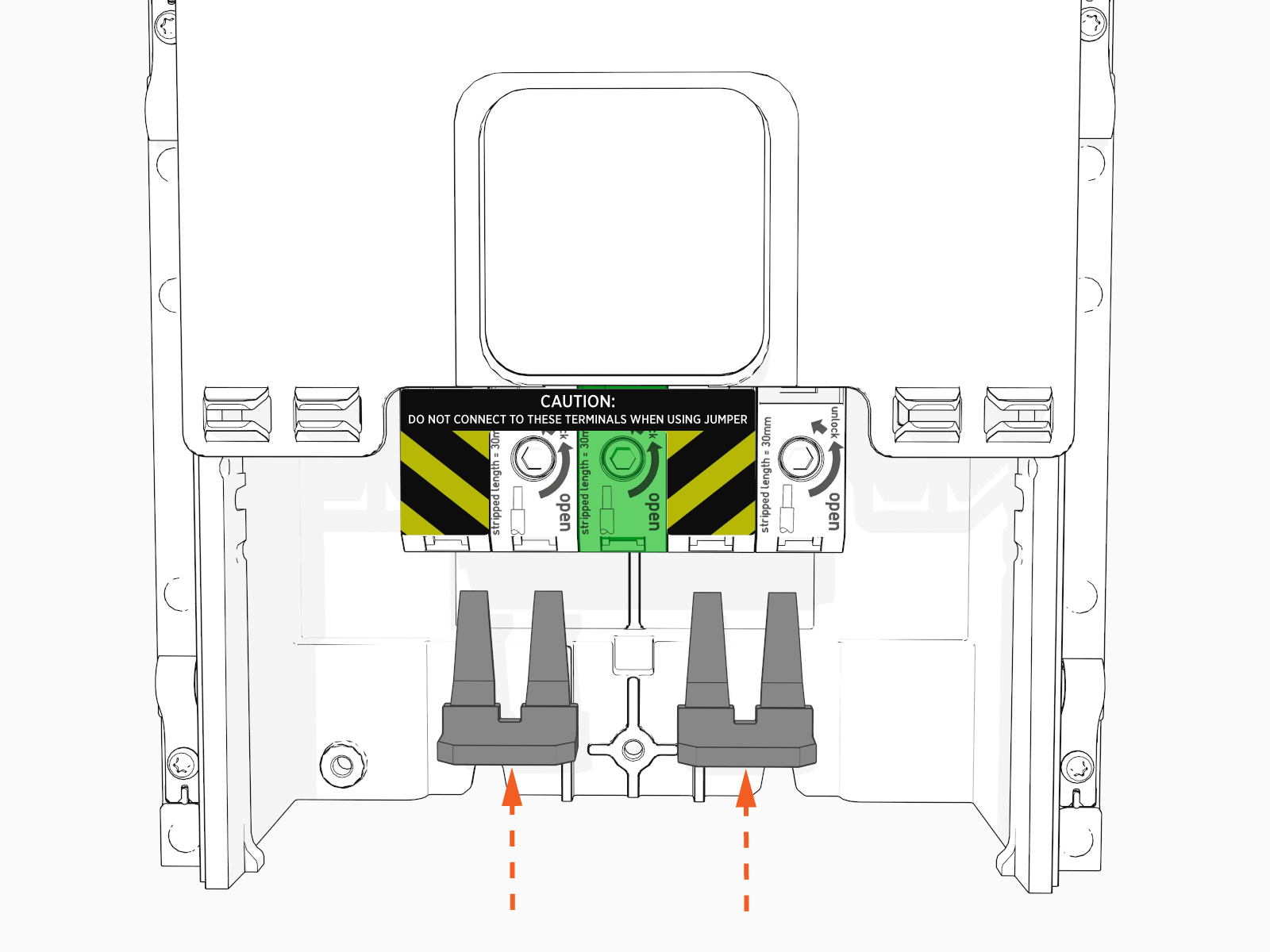 Ensure circuit sharing jumpers are fully seated.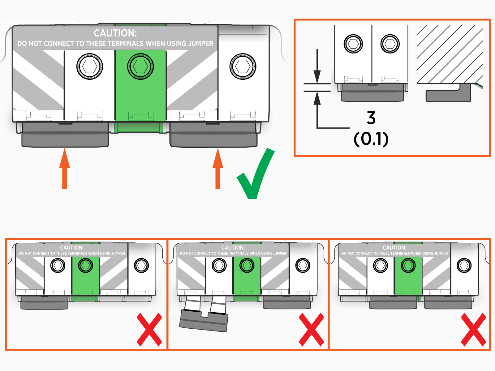
-
-
Align the power plate with the housing and slide it down until it fully seats on the metal bracket.
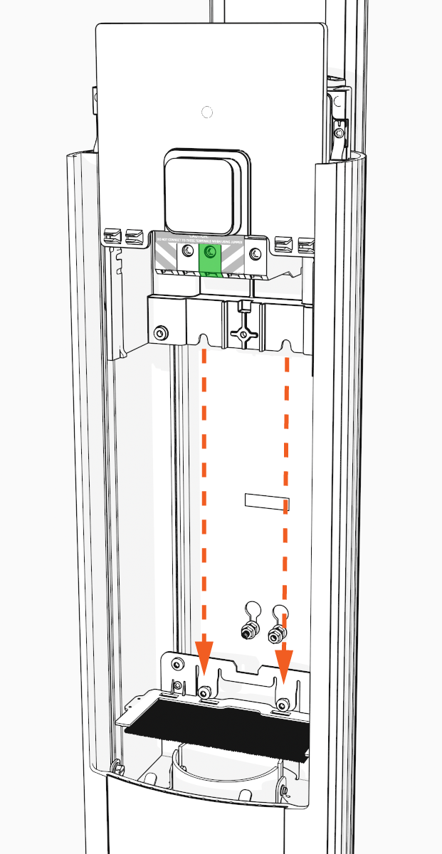 Avoid damaging the shunt trip cables when routing.
 -
Ensure the power plate is seated correctly.
-
Using a T25 torque driver, torque the screws to 5.7 Nm (50 in-lb) to secure the power plate.
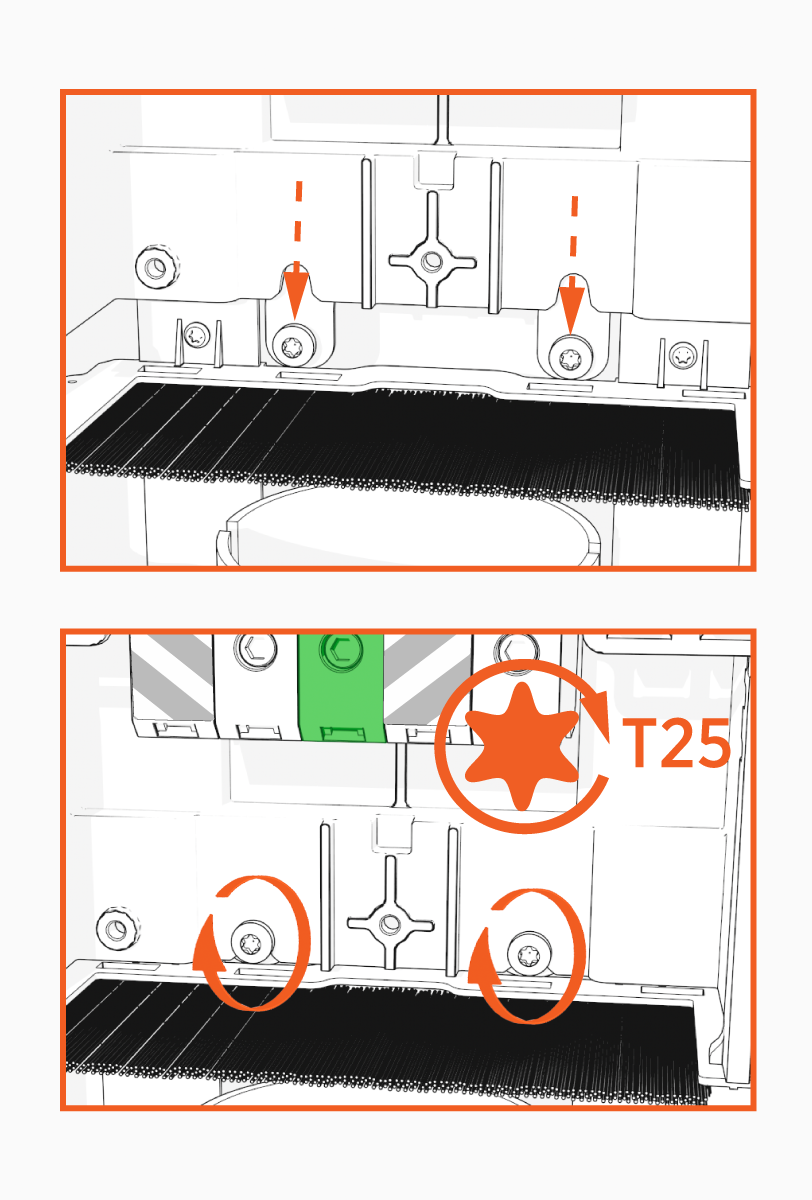
-
Ensure the power plate is fully seated. Ensure the power plate is fully seated. If the distance from the top of the power plate to the top of the pedestal does not equal 286 +/- 1 mm (11.26 in) (a), contact ChargePoint Support.

-
Reconnect the wiring before installing the power plate cover as follows:
-
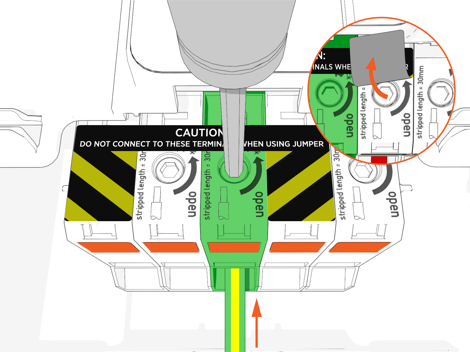
To open the center terminal block, insert an 8 mm (5/16 in) hex driver and rotate it counterclockwise. You might need to lift the label flap to access the terminal block.
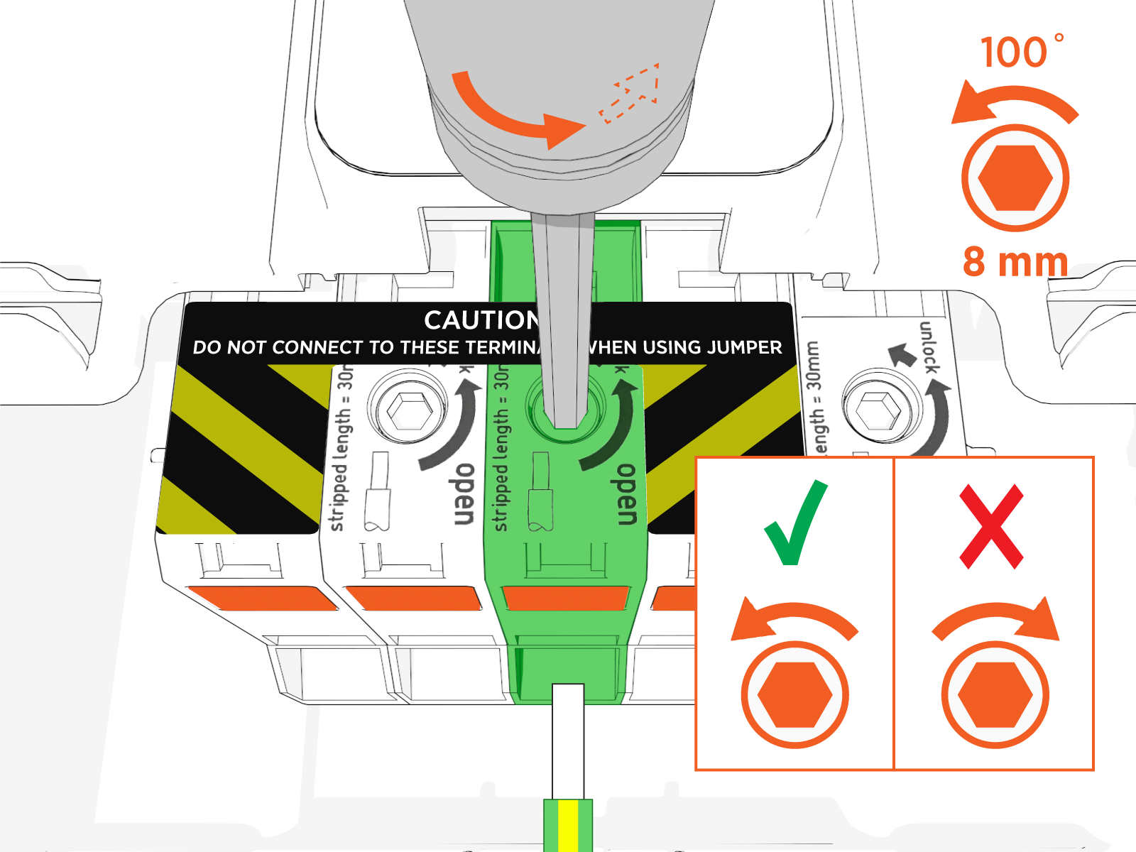
-
Hold the driver in place to keep the terminal open while inserting the wire.
 If you use the orange button to lock the terminal block in the open position, use only counterclockwise rotation to release it. Rotating the tool clockwise will damage the terminal block.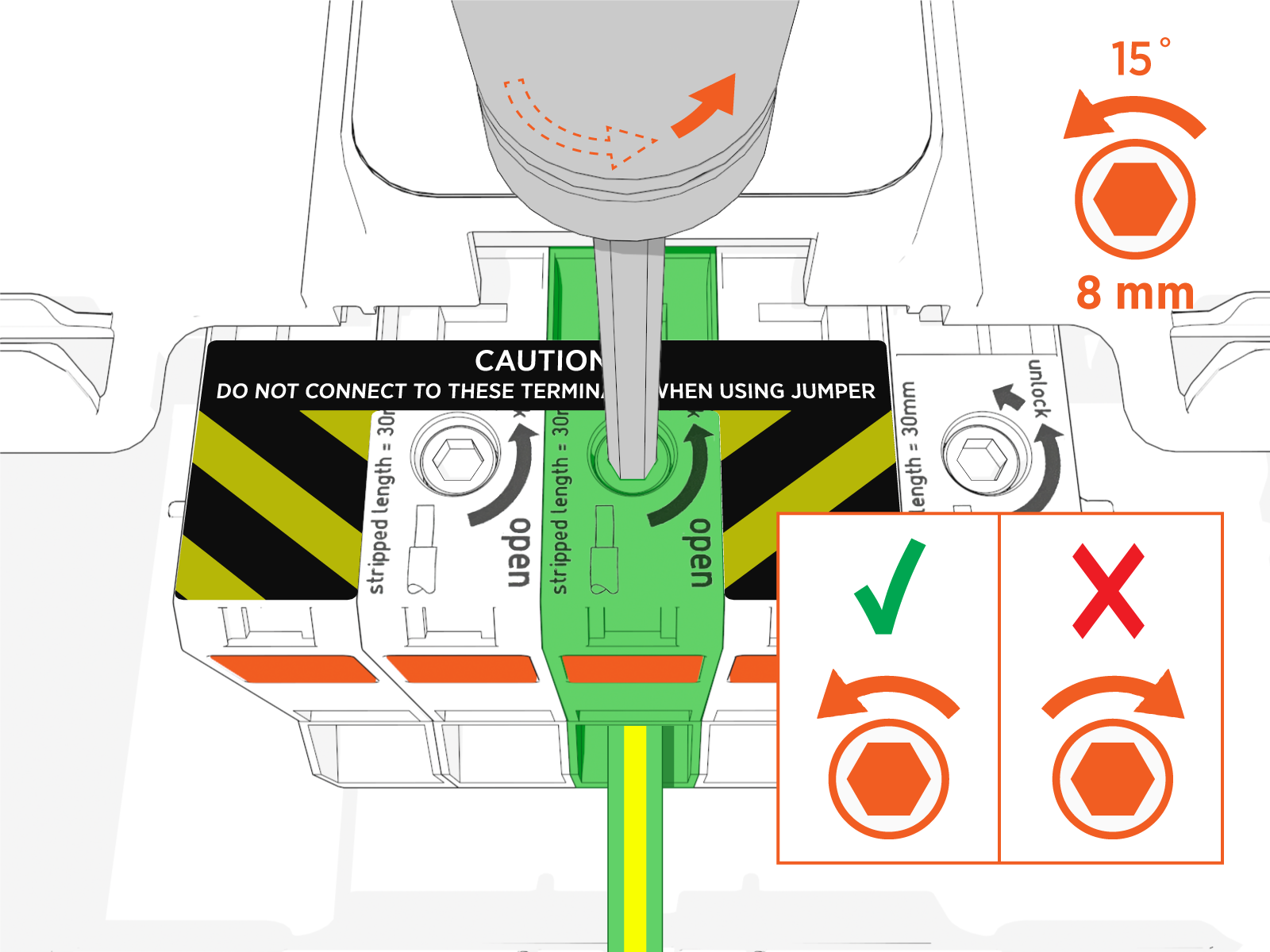
-
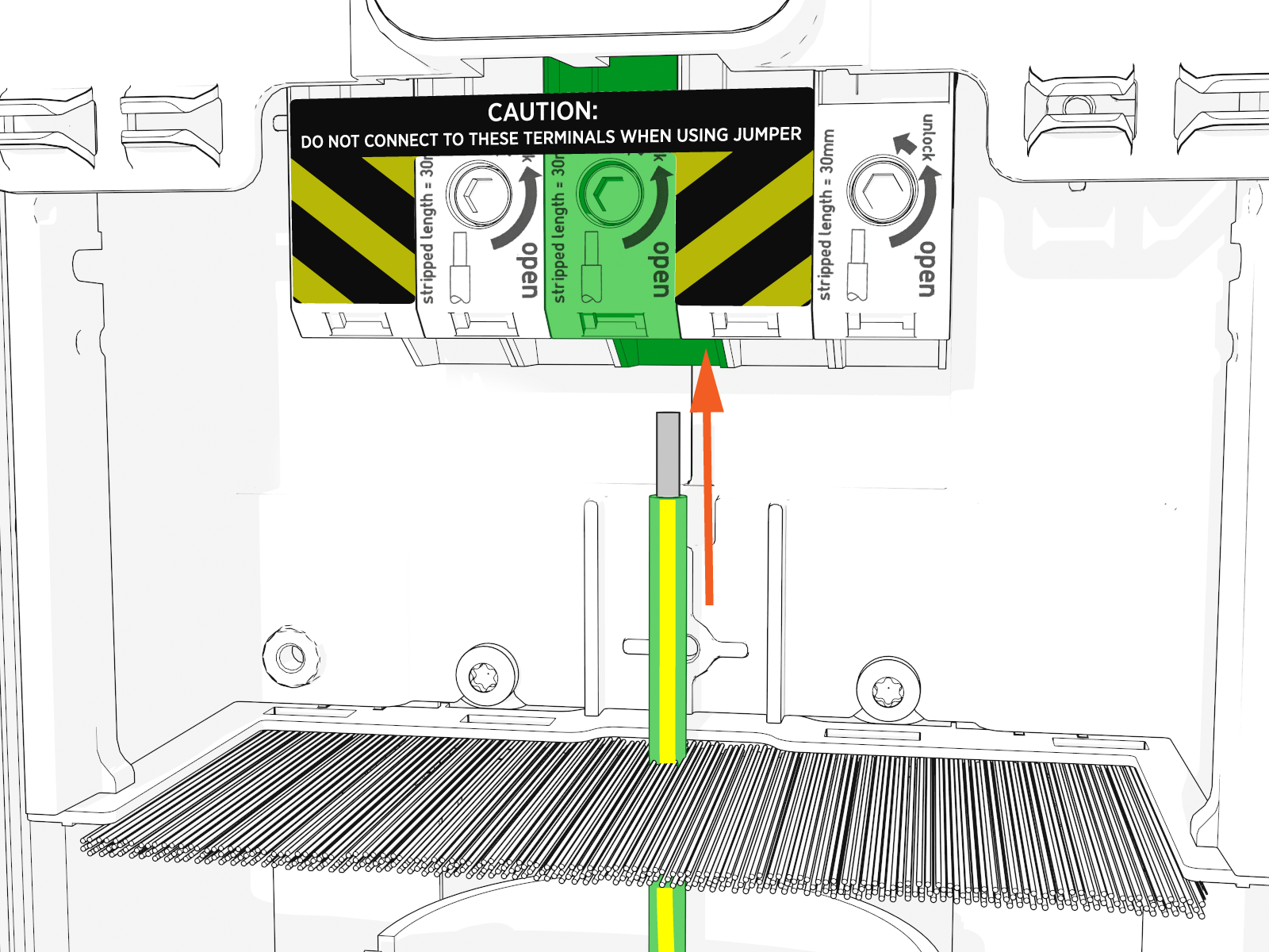
Insert the ground wire into the center terminal.
-
While holding the wire in place, release the hex driver to secure the wire in the terminal block.
-
Repeat previous steps for each wire.
You should not see any copper wire outside the terminal block. Ensure to turn ON the breaker. If you previously unplugged the Ethernet cables, make sure to plug them back in.
-
-
Align the rails on the head assembly with the pedestal and slide all the way into the pedestal housing.

-
Ensure the head assembly is fully seated.

-
Using the L-wrench, hand tighten the two screws.

-
Slide the top cap onto the head assembly, adjusting as necessary to clear the charge cables, until it fits into place.

-
Torque two captive screws to 1.1 Nm (10 in-lb).

-
Insert the charging cables into their corresponding holsters.

-
At the electrical panel, power up the station.
One or both port LEDs appear Red until the lockout faults are cleared.
Next Steps
Clear Lockout Faults
When you replace a part, the station triggers lockout faults.
To clear lockout faults, go to chargepoint.com/support and contact technical support using the appropriate region-specific number.
