Replace the Head Assembly
To replace the head assembly, perform the following steps:
Required Tools and Materials
|
|
Torx screwdriver (T25) |
|
|
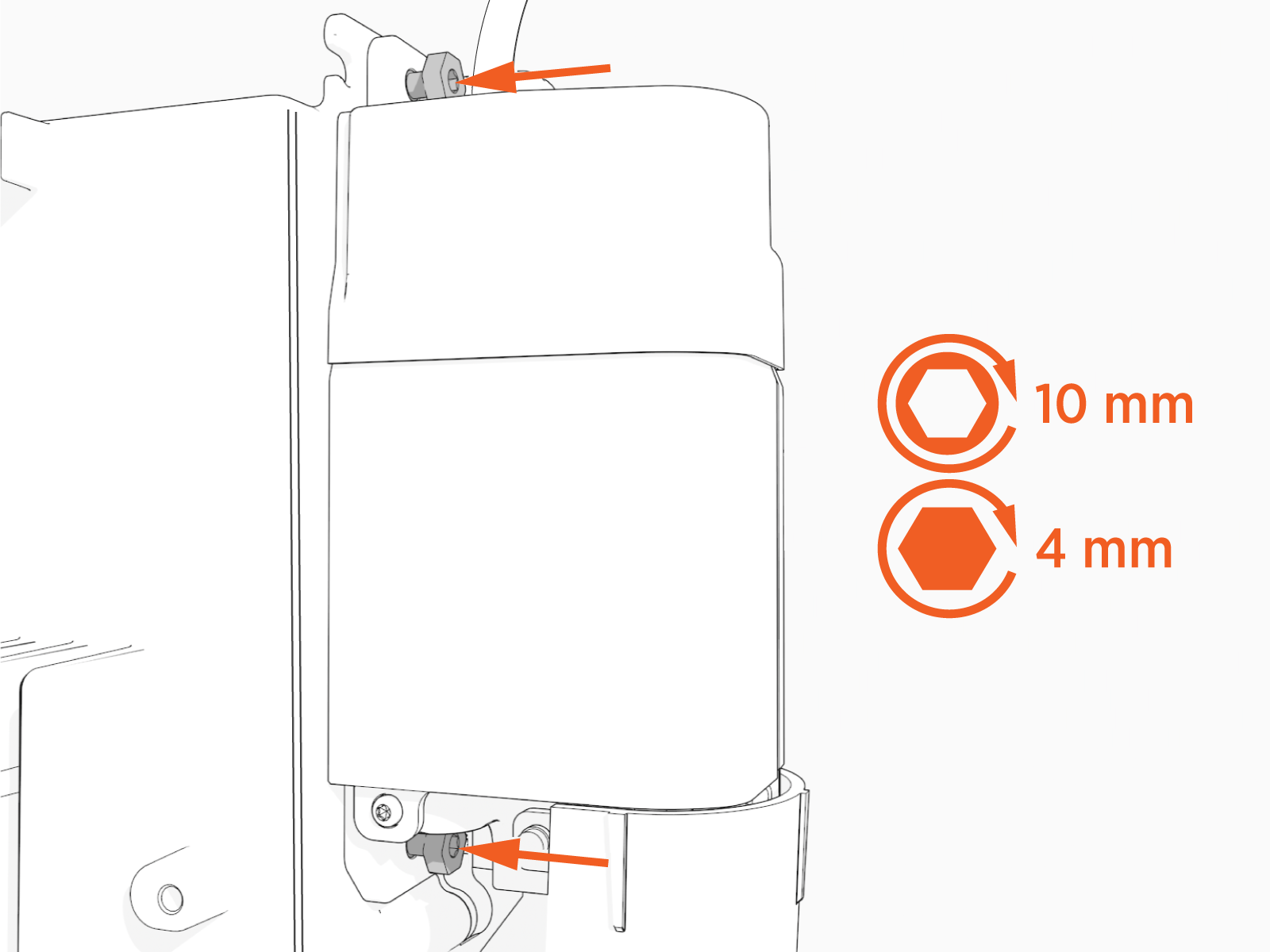
4 mm hex wrench
|
|
|
10 mm socket
|
|
|
Protective cut-proof gloves |

Remove the Smart Cable Assemblies
To remove the Smart Cable Assemblies, perform the following steps:
-
Use your ChargePoint card or the mobile app to wake the station up.
If the station does not have power, contact the station owner to learn when power will be available and discuss appropriate next steps.If you do not have a ChargePoint account, go to chargepoint.com/support, find your region's technical support number, and contact ChargePoint Support.
-
Unlock the charging cables and set them down gently.
-
Disconnect the power to the CP6000 at the service panel.
-
Before any procedure, the technician must disconnect the power.
-
Follow local code to de-energize the applicable circuit and lock out/tag out the disconnect before proceeding. Use a multimeter to test that power is off.
-
Keep power off until the top cap is correctly reinstalled and the work is complete.
-
Use the L-wrench to loosen two captive screws securing the top cap.

-
Remove the top cap.

-
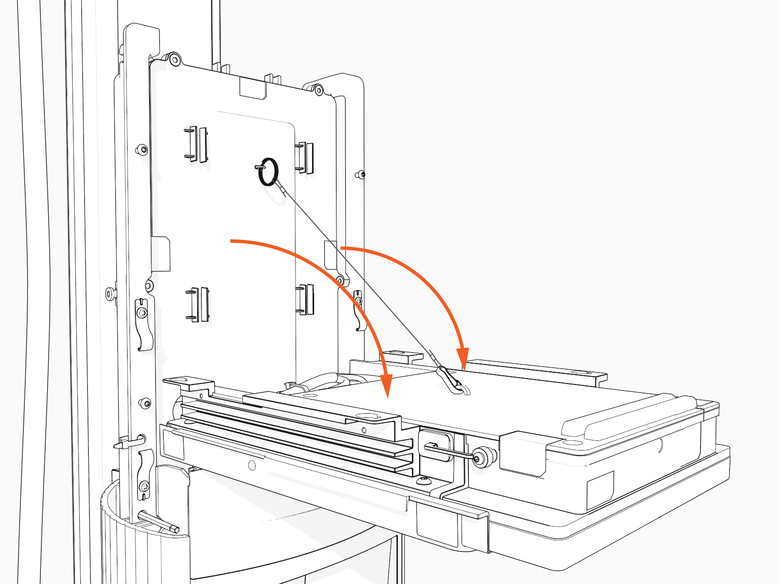
Use the L-wrench to loosen, but do not remove, the screws securing the head assembly.

-
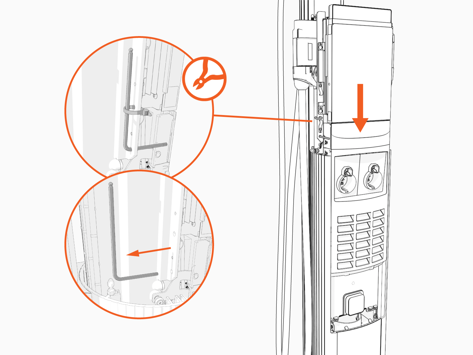
Lift head assembly. Insert an L-wrench or a screwdriver through the hole on the side of the head assembly to hold the head assembly in the raised position.

-
Using a T25 driver, loosen, but not remove, four M4 screws that secure the Control and Communications Unit (CCOM
 Control and Communications Module) to the head assembly.
-
Lift the CCOM
Control and Communications Module up and tilt it away from the head assembly. The bottom edge of the CCOM
Control and Communications Module rests on the upper edge of the holster assembly.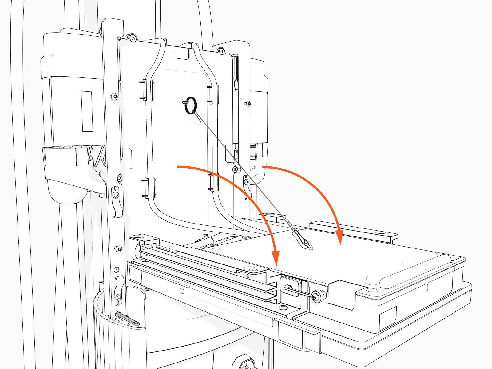
-
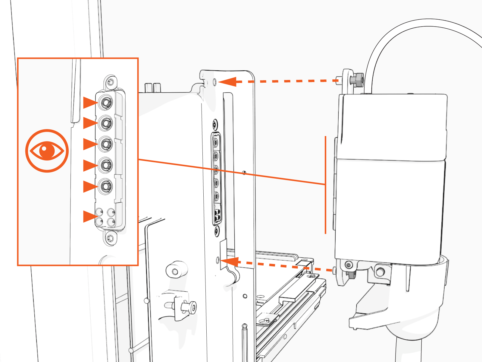
Unsnap the RJ45 Ethernet cables.

-
Disconnect the RJ45 Ethernet cables from the CCOM
Control and Communications Module.
-
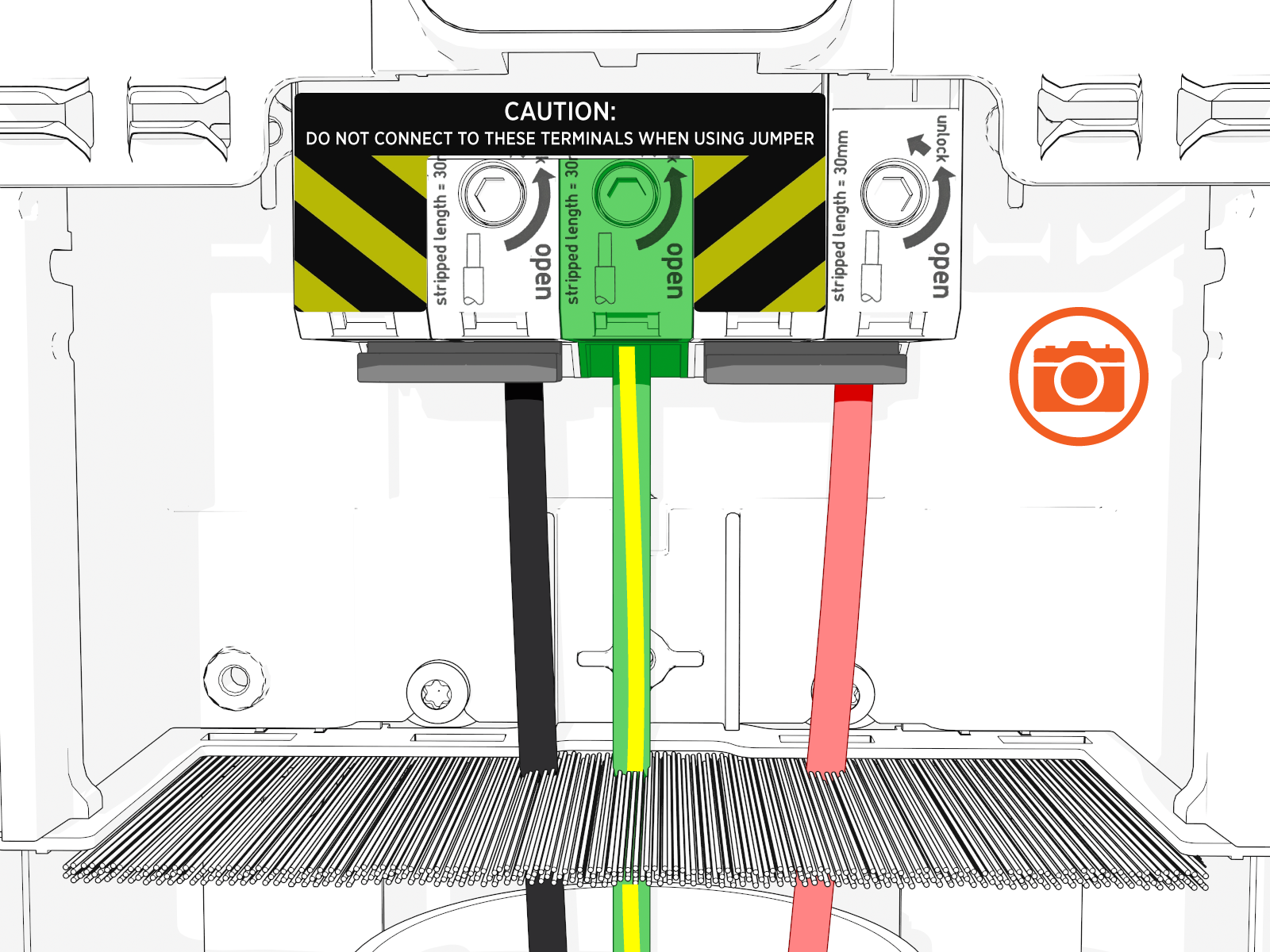
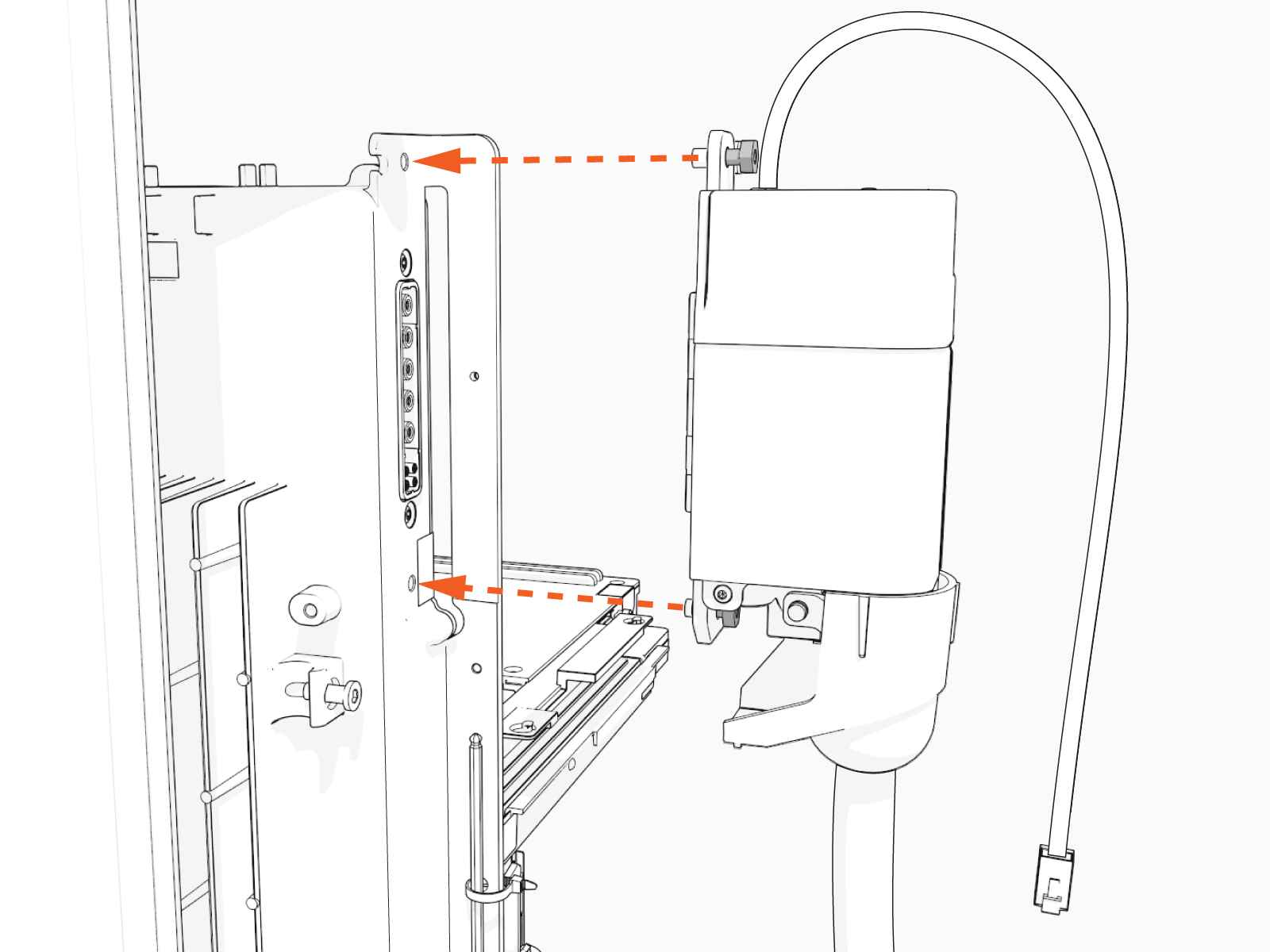
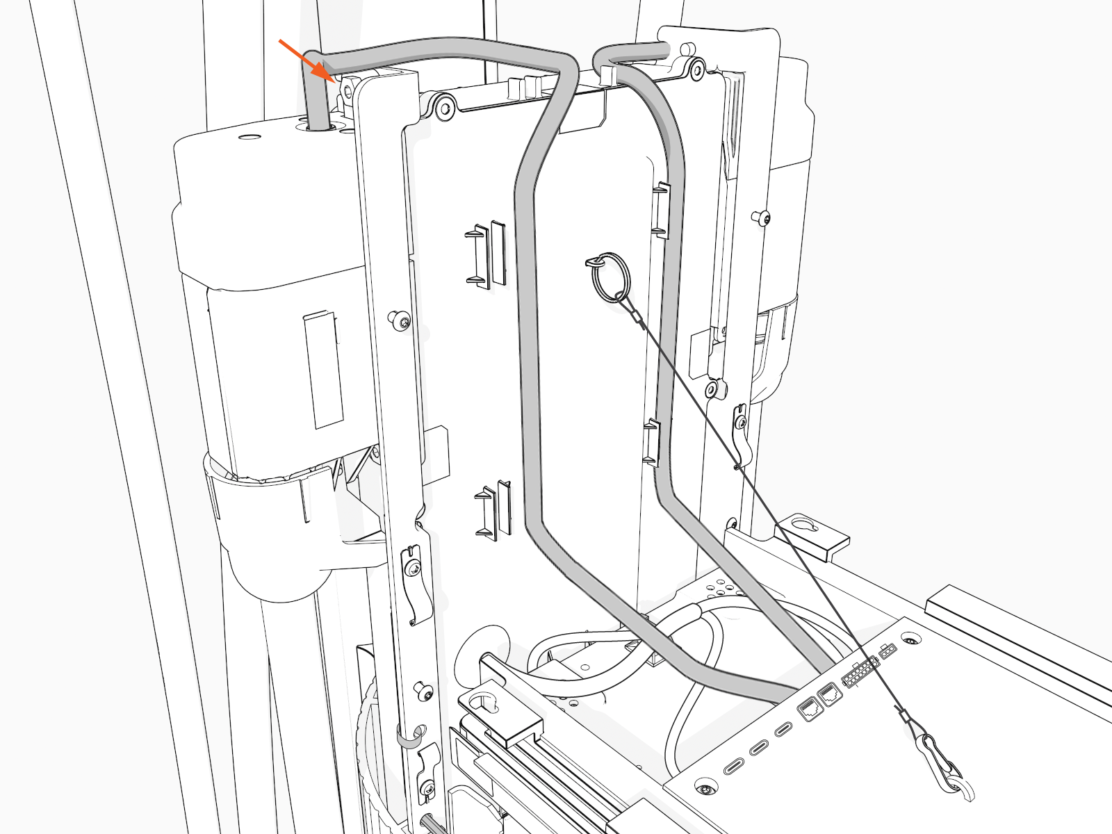
Loosen the top and bottom screws securing the smart cable.
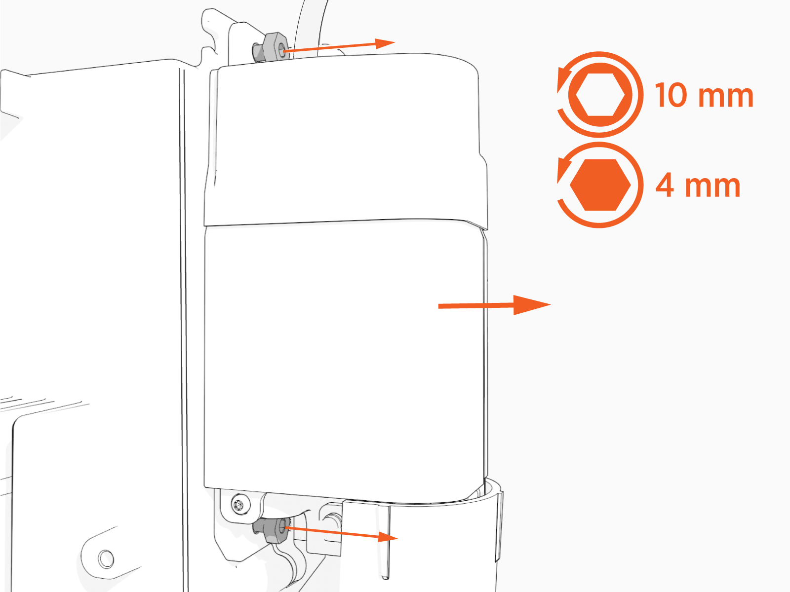
-
Remove the smart cable.
Avoid damaging connector pins when removing the smart cable.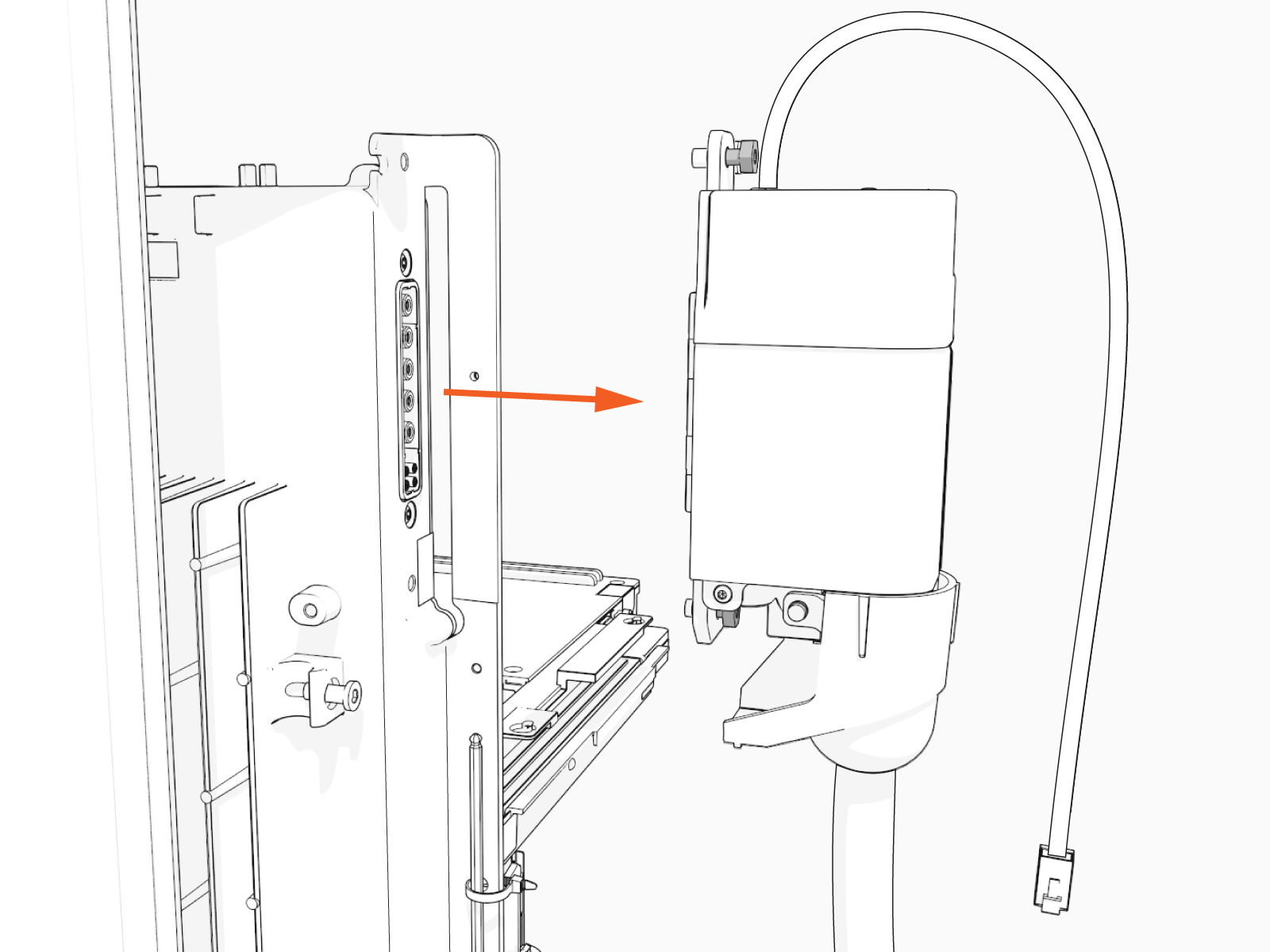
-
Set the cable gently aside.
-
Repeat the previous steps for the second cable.

Risk of shock
Failure to follow these instructions can result in serious injury, loss of life, or property damage.
Remove the Head Assembly
To remove the Head Assembly, perform the following steps:
-
Raise the CCOM
Control and Communications Module and slide it into place on the head assembly.
-
Tighten the screws to secure the CCOM
Control and Communications Module.
-
Lift the head assembly to remove it from the pedestal or wall mount enclosure. Set it gently on a padded surface.
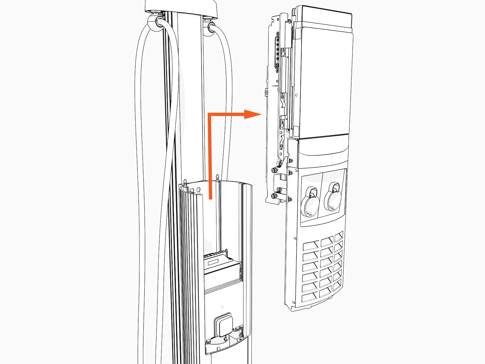
-
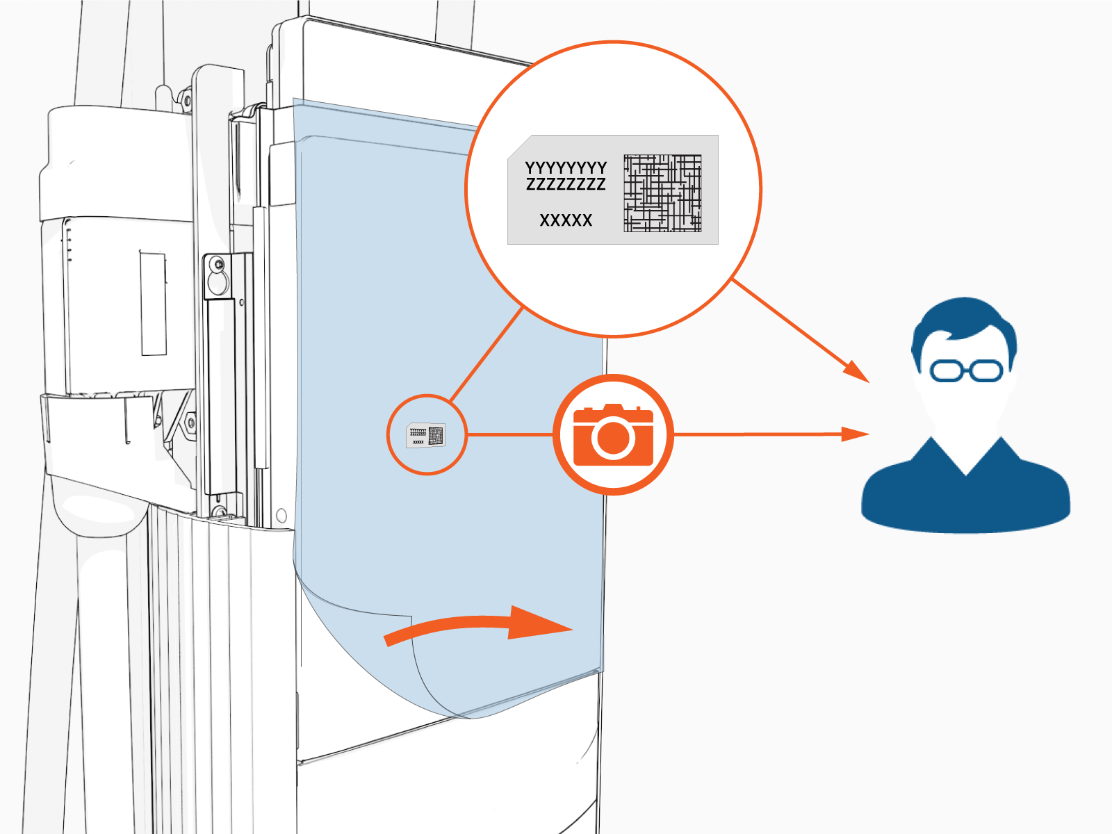
Take a picture of the completed terminal block wiring with labels. This picture is required to complete the setup process.
Install the Head Assembly
To install the Head Assembly, perform the following steps:
-
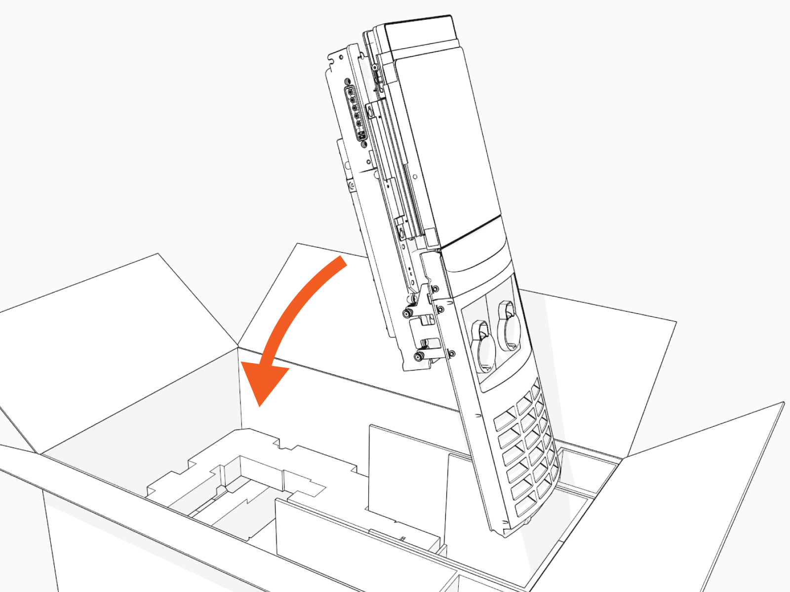
Remove the head assembly from the packaging by holding the metal castings. Save the packaging and use it to return the removed part to ChargePoint.
Wear protective gloves. Hold the metal edges of the head assembly, not the plastic front cover, to avoid damaging the front cover.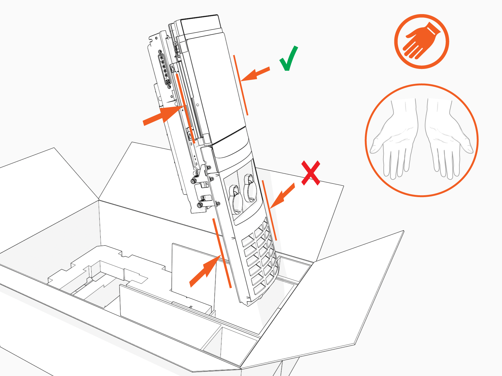
-
Align the rails on the head assembly with the pedestal and slide it into the pedestal housing.
Avoid damaging cables when installing the head assembly.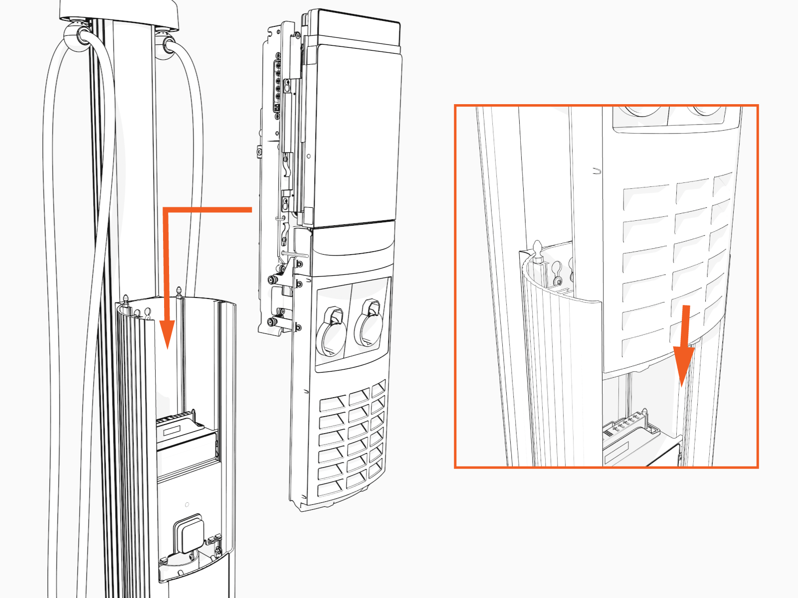
The head assembly rests on the L-wrench connected to the side of the assembly.
-
Loosen the screws that secure the Control and Communications Unit (CCOM
Control and Communications Module). -
Lift the CCOM
Control and Communications Module up and tilt it away from the head assembly. The bottom edge of the CCOM
Control and Communications Module rests on the upper edge of the holster assembly.
-
Ensure there is no visible damage to the connector pins.
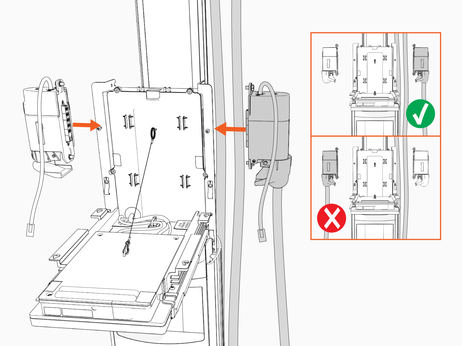
Attach the smart cable by partially engaging one screw and then partially engaging the second screw.
-
On single port stations, attach the smart cable to the right side as you are facing the charging station. Connect the blank connector to the left side.
-
Torque both the top and bottom screws to 1.1 Nm (10 in-lb) to secure the smart cable.
-
Connect the RJ45 Ethernet cables from the smart cable assembly to the bottom of the CCOM
Control and Communications Module.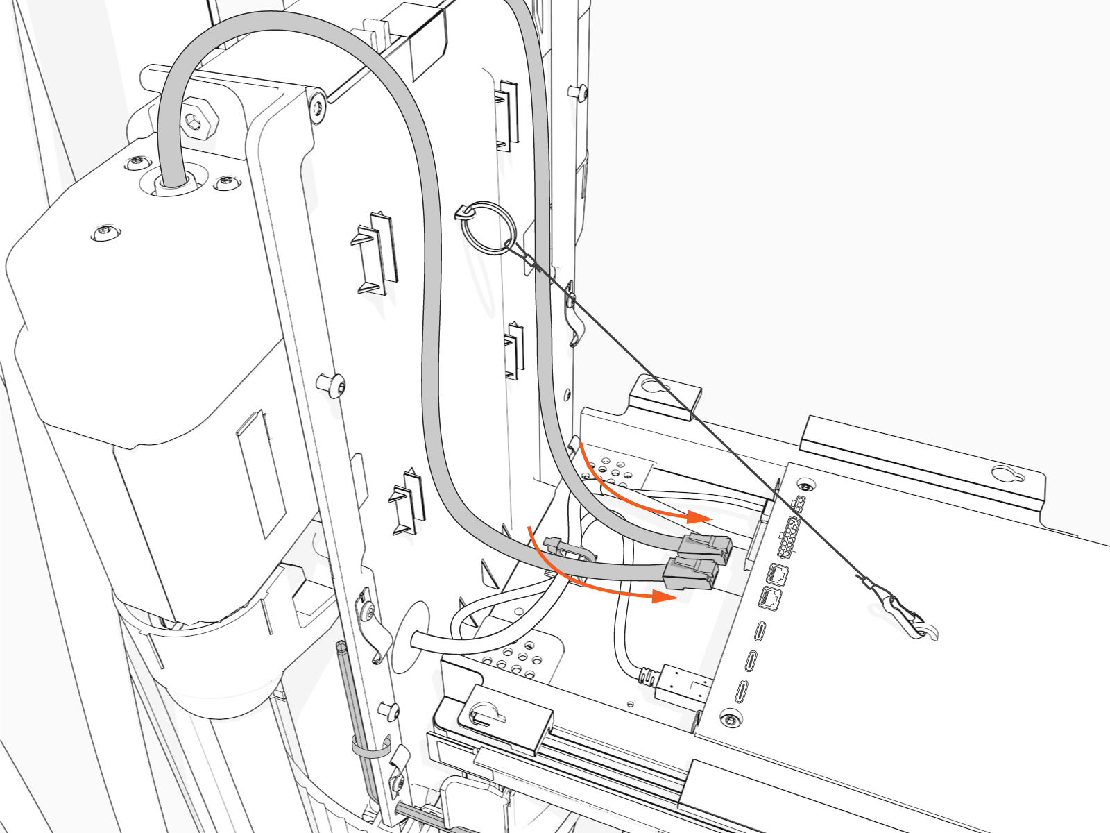
-
Slide the RJ45 Ethernet cables into the slots.
-
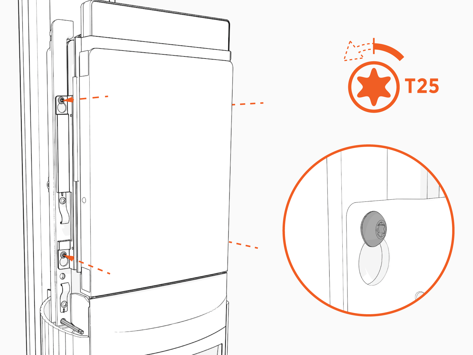
Raise the CCOM
Control and Communications Module and slide it into place on the head assembly. 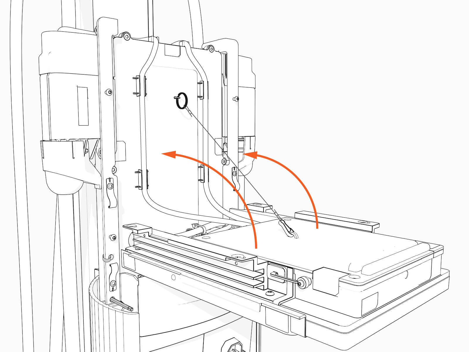
-
Torque the screws to 1.7 Nm (15 in-lb) to secure the CCOM
Control and Communications Module.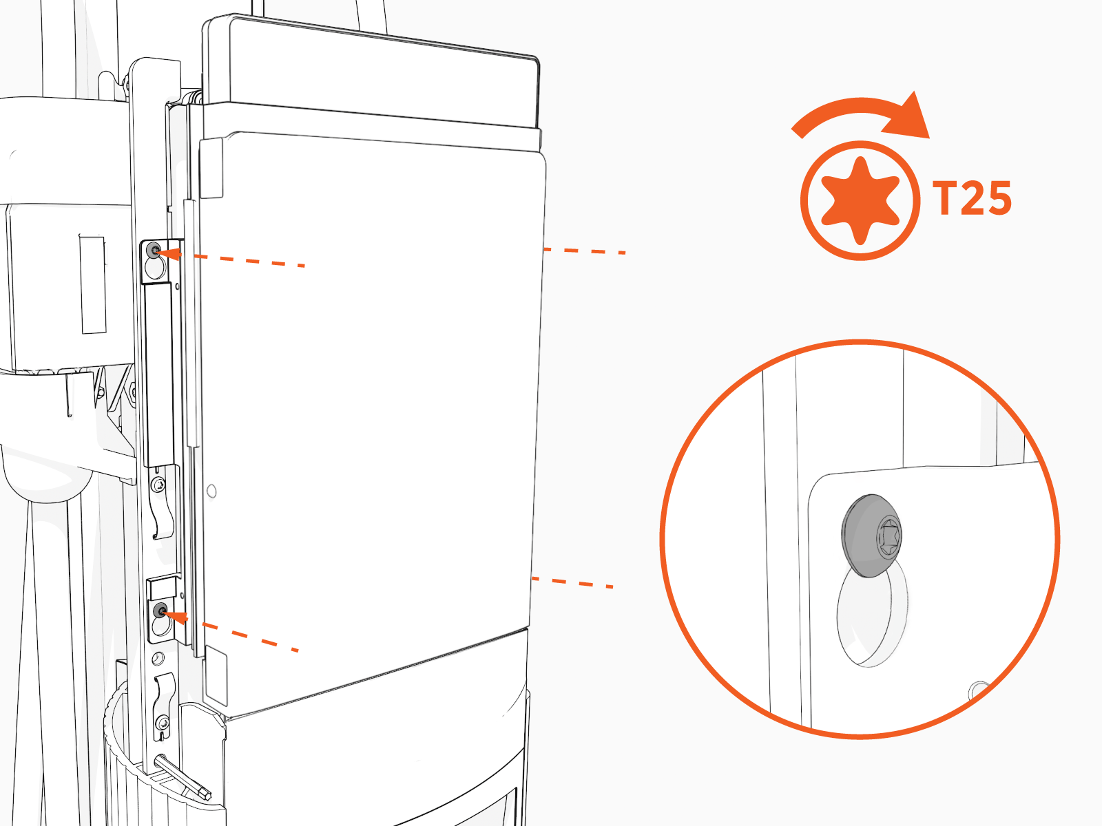
-
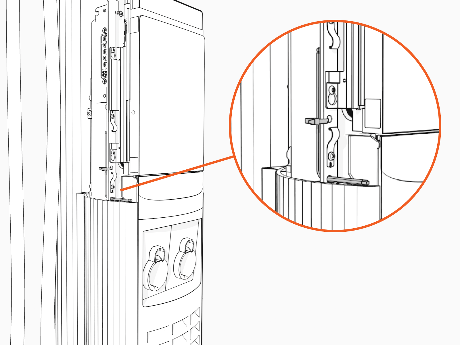
Remove the L-wrench. Slide the head assembly all the way into the pedestal housing.
-
Ensure the head assembly is fully seated.

-
Using the L-wrench or 4 mm hex tool, tighten two screws.

-
Take a picture of the activation label, remove the protective film, and give the protective film with the label to the station owner.
-
Slide the top cap onto the head assembly, adjusting as necessary to clear the charging cables, until it fits into place.

-
Torque two captive screws to 1.1 Nm (10 in-lb).

-
At the electrical panel, power up the station.
One or both port LEDs appear Red until the lockout faults are cleared.
Next Steps
Use either one of the following two methods to configure and pinpoint the charging station:
-
ChargePoint Installation Wizard and Pinpoint Portal
OR
-
ChargePoint Installer app
Installation Wizard and the Pinpoint Portal
When you power up the charging station, the on-screen Installation Wizard runs. The wizard verifies operation of the station and performs basic setup tasks.
Before running the Installation Wizard, ensure you have:
-
The new charging station’s activation label (located on the plastic film protecting the front of the charging station; a spare label is included in the shipping box)
-
Smartphone or laptop with a QR
Quick Response-code scanner, camera, and Internet connection -
Your ChargePoint Certified Installer user name and password
The Installation Wizard includes these tasks:
-
Set a language for the Installation Wizard.
This does not permanently affect the station’s display language. Choose the language most convenient to you. -
Configure power
-
Check for faults
-
Test network connectivity
-
Complete the post-installation checklist
If your smartphone has a scanning app:
Perform the following steps if your smartphone has a scanning app:
-
Open a QR
Quick Response code scanning app.Point the camera at the QR
Quick Response code on the activation sticker.
Your device is automatically redirected to the installer pinpointing page. Confirm that the URL of the page is o.chargepoint.com.

-
Log into the installer site using your installer login. Tap Log In.
-
Confirm the MAC
Message Authentication Code address and activation password are automatically entered and correct. -
Tap Next.
-
Follow the prompts to complete the pinpointing process.
If your smartphone does not have a scanning app:
Perform the following steps if your smartphone does not have a scanning app:
-
Using your smartphone, navigate to o.chargepoint.com.
-
Enter the MAC
Message Authentication Code address and activation password printed on the activation label. -
Tap Next.
-
Follow the prompts to complete the pinpointing process.
ChargePoint Installer App
Use the ChargePoint Installer App to complete the station setup procedure.
-
If you do not already have the Installer app, scan the QR
Quick Response code to download the app, and sign up.
-
Open the ChargePoint Installer app and log in.
-
Select Configure.
-
Confirm you have all required materials to continue activation, and select Yes.
-
Follow the prompts in the Installer app.
Clear Lockout Faults
When you replace a part, the station triggers lockout faults.
To clear lockout faults, go to chargepoint.com/support and contact technical support using the appropriate region-specific number.
Return Head Assembly
Do not discard the part you are replacing. Reuse the packaging from the new part to return all removed parts to ChargePoint.
For assistance, go to chargepoint.com/support, find your region’s technical support number, and contact ChargePoint Support.
