Replace a Wall Mount
Required Tools and Materials
|
|
Torx screwdriver (T25) |
|
8mm hex driver |
|
|
10 mm hex socket |
|
Electric drill |




Before you Begin
Risk of shock
-
Before any procedure, the technician must disconnect the power.
-
Follow local code to de-energize the applicable circuit and lock out/tag out the disconnect before proceeding. Use a multimeter to test that power is off.
-
Keep power off until the top cap is correctly reinstalled and the work is complete.
Failure to follow these instructions can result in serious injury, loss of life, or property damage.
Remove the Power Plate
To remove the power plate, perform the following steps:
-
Before removing the power plate, disconnect the wiring.
-
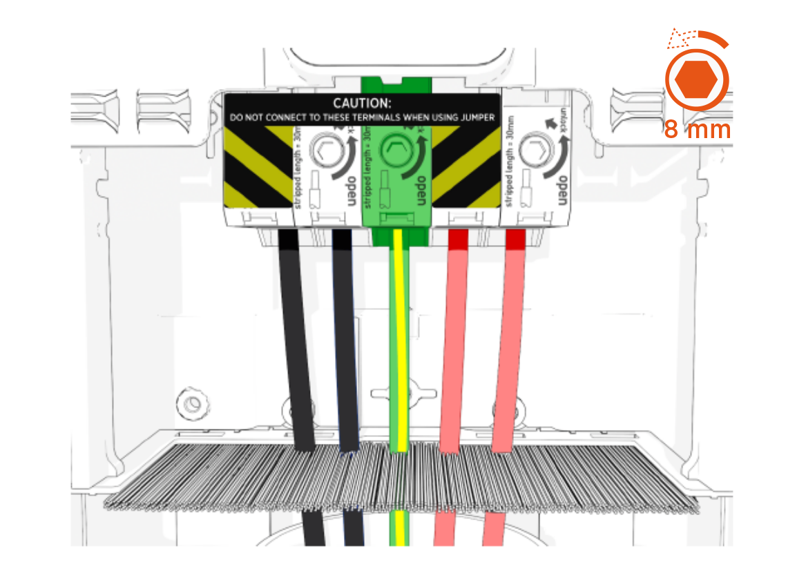
To disconnect wiring in the terminal block, insert an 8 mm (5/16 in) hex driver and rotate it counterclockwise.
-
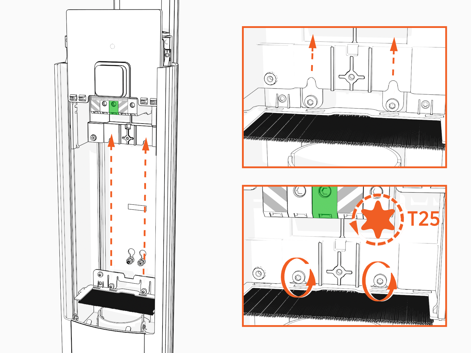
Using a T25 torque driver, loosen but do not remove screws.
-
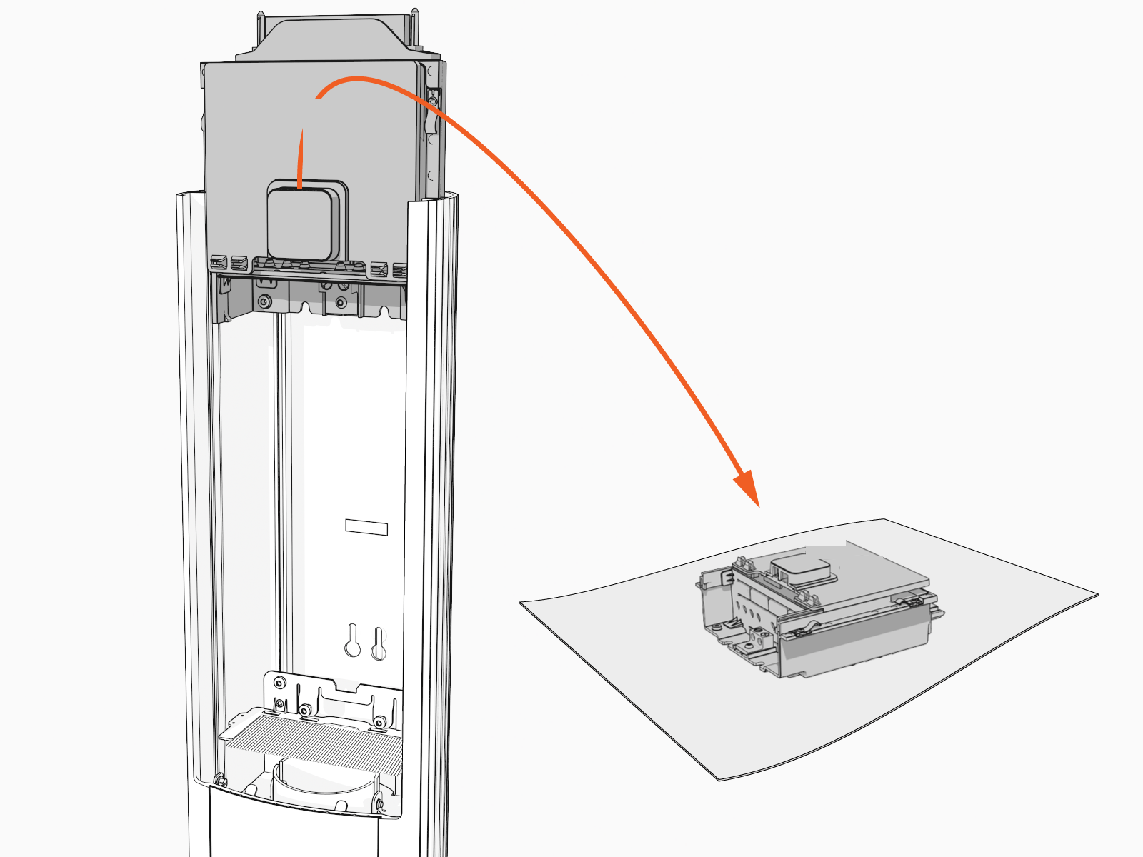
With the screws still in place, carefully lift the power plate upward to remove it from the metal bracket.
-
Ensure the power plate is completely removed.
-
Verify that no components or cables are obstructed after removal.
Remove the Wall Mount
To remove the wall mount, perform the following steps:
-
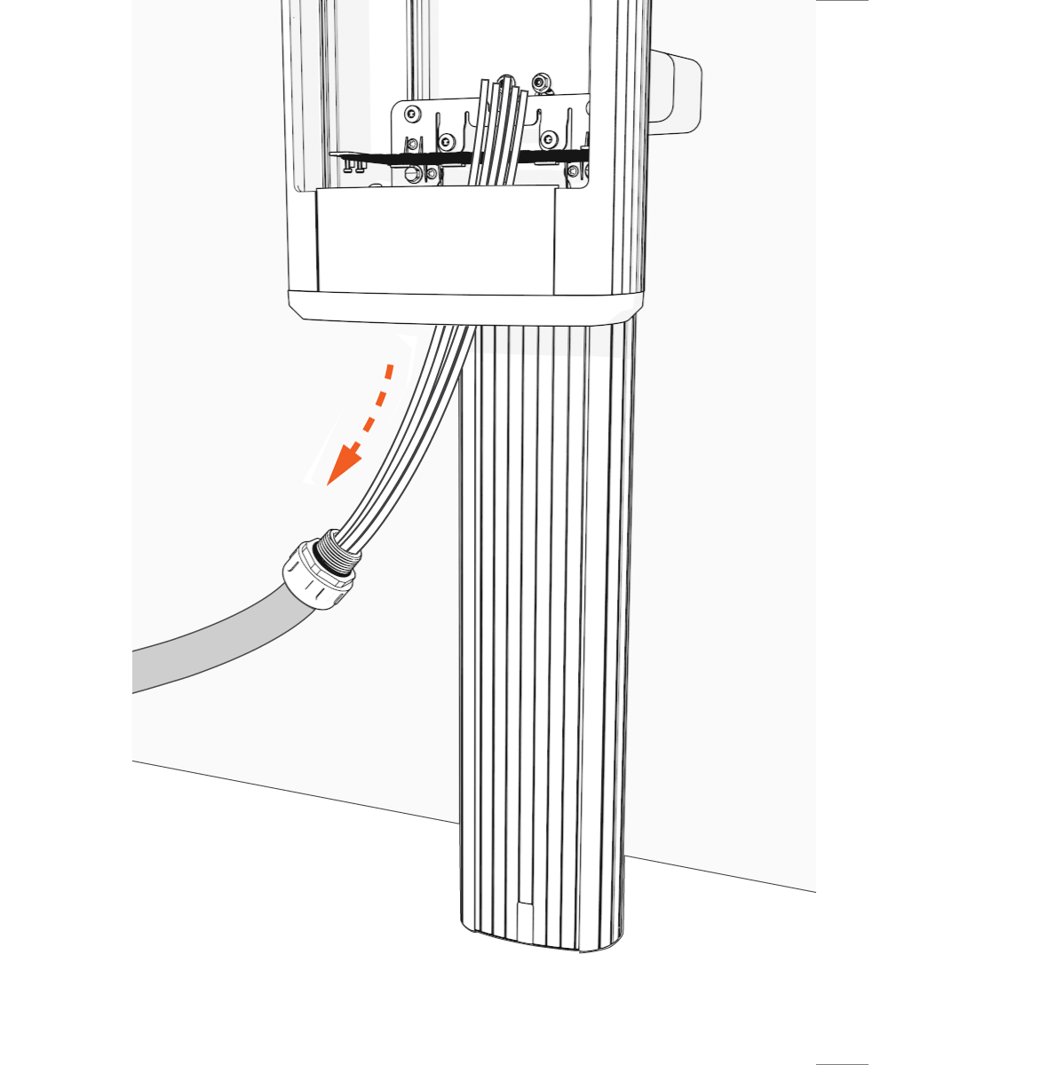
Remove conduit wire from the station through the lower station bracket.
-
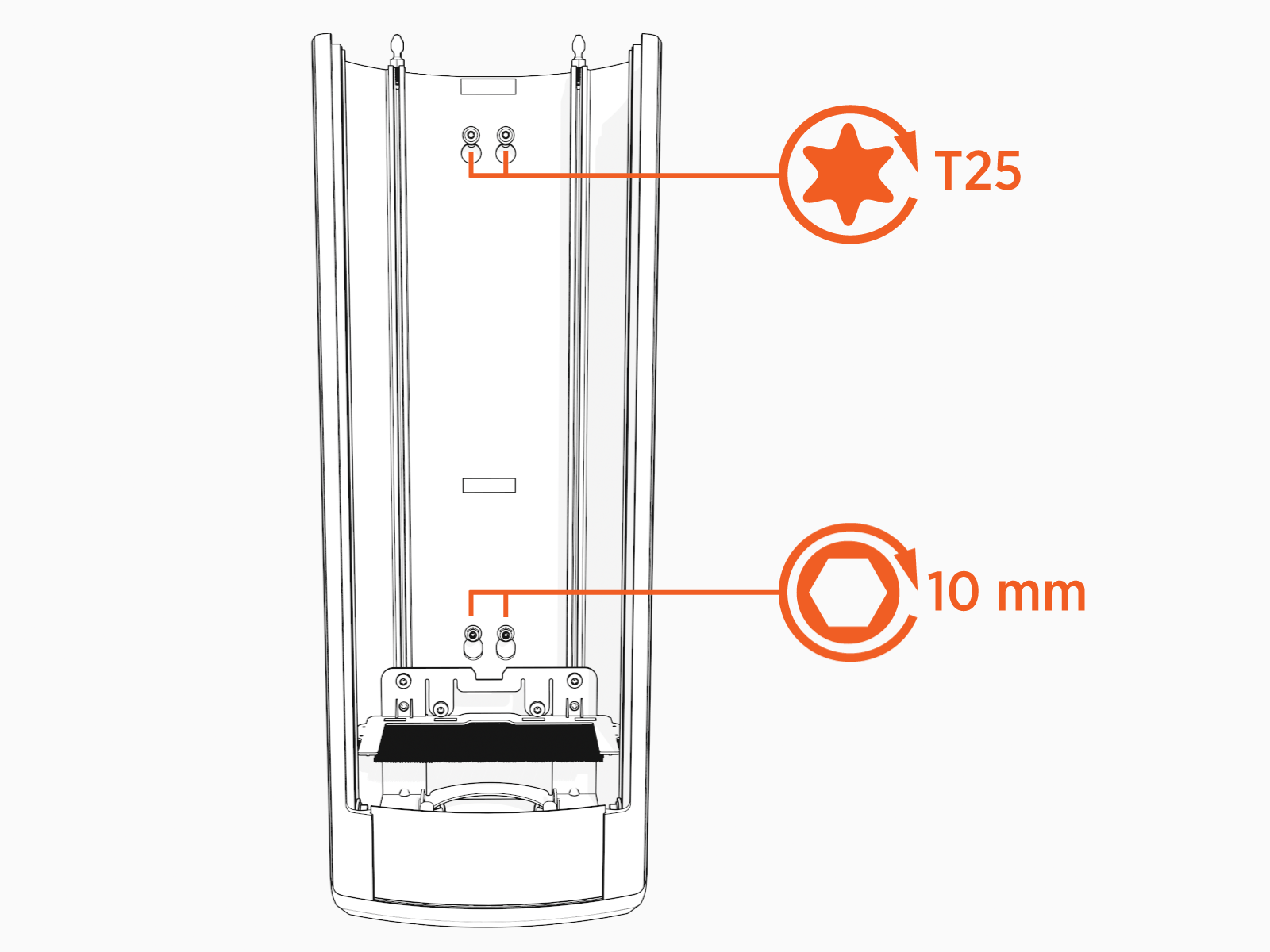
Loosen the top screws using the T25 torx screwdriver and bottom nuts using the 10mm hex socket.
Torque the screws to 5.7 Nm value.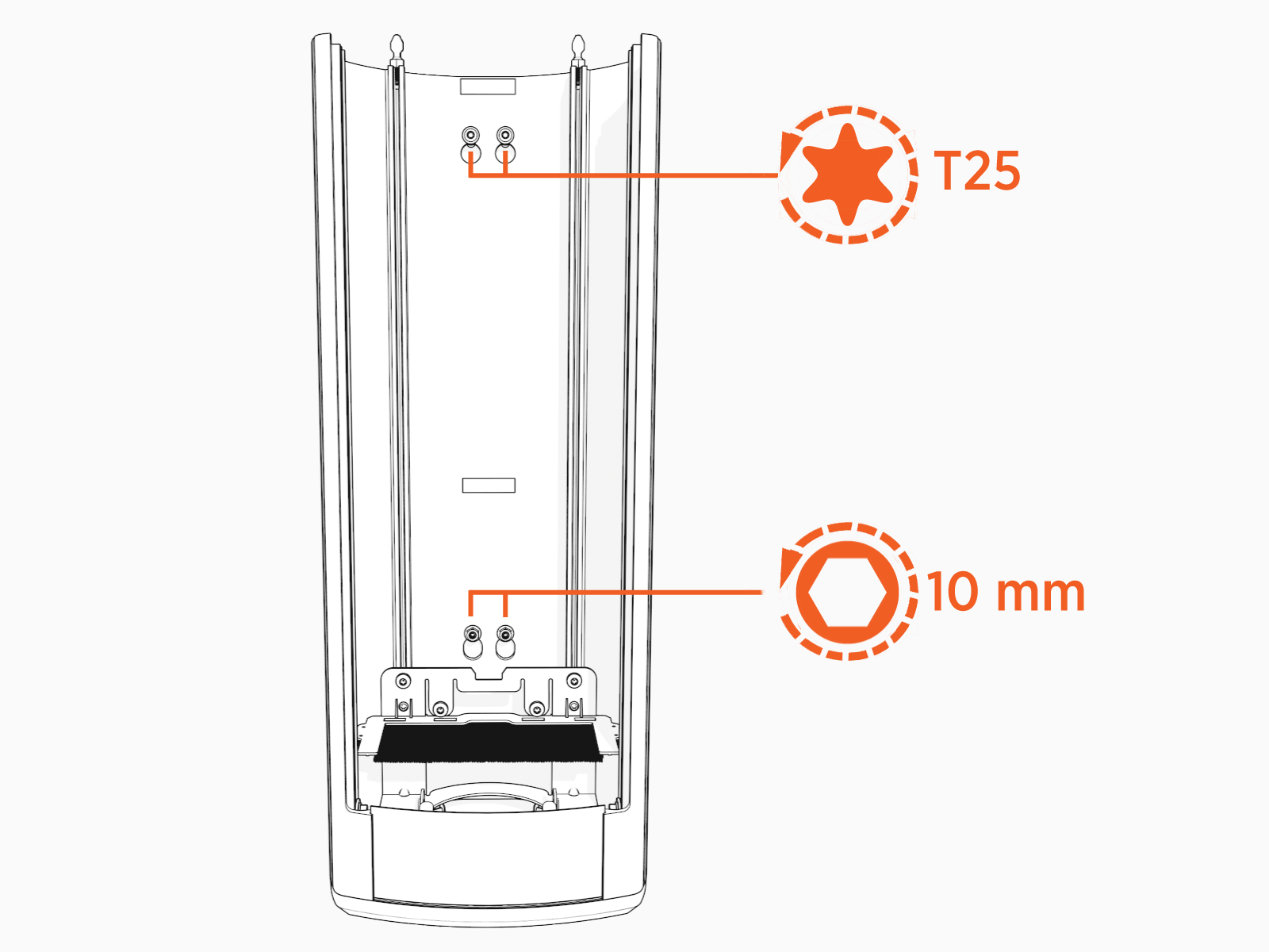
-
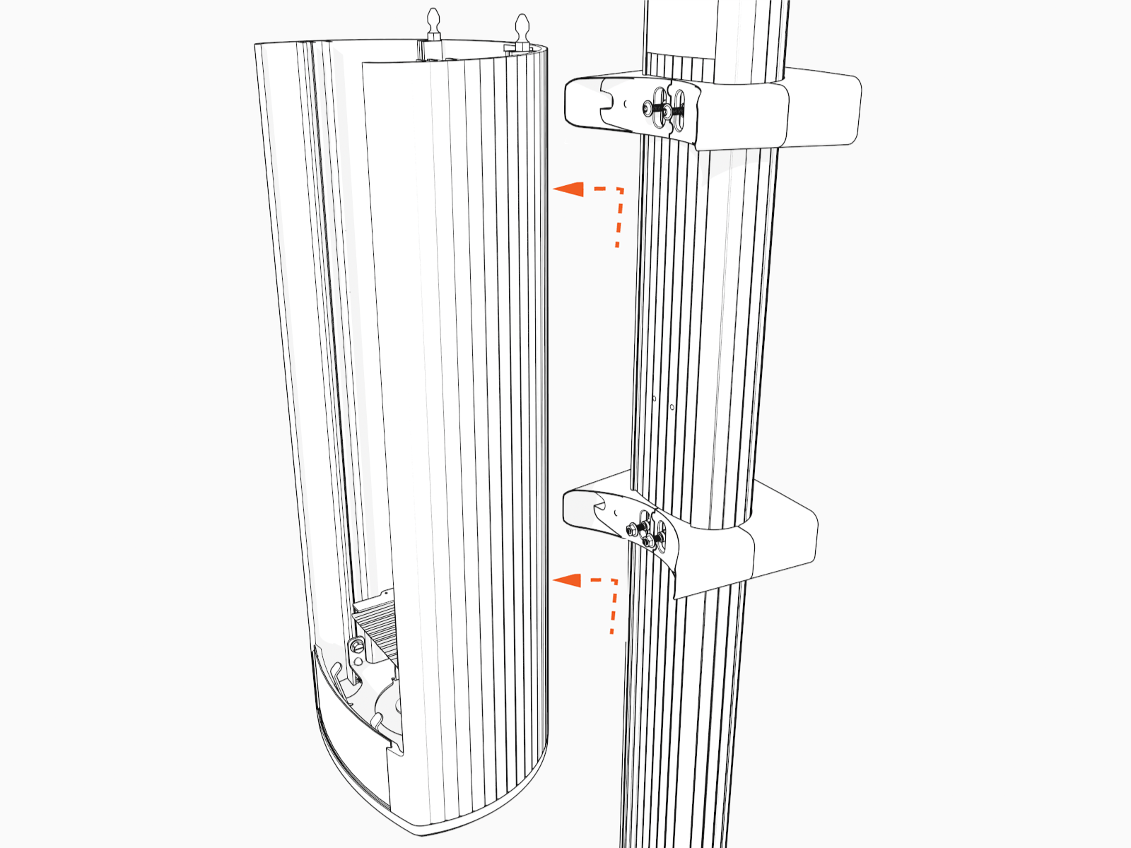
Lift the housing up and away from the station.
-
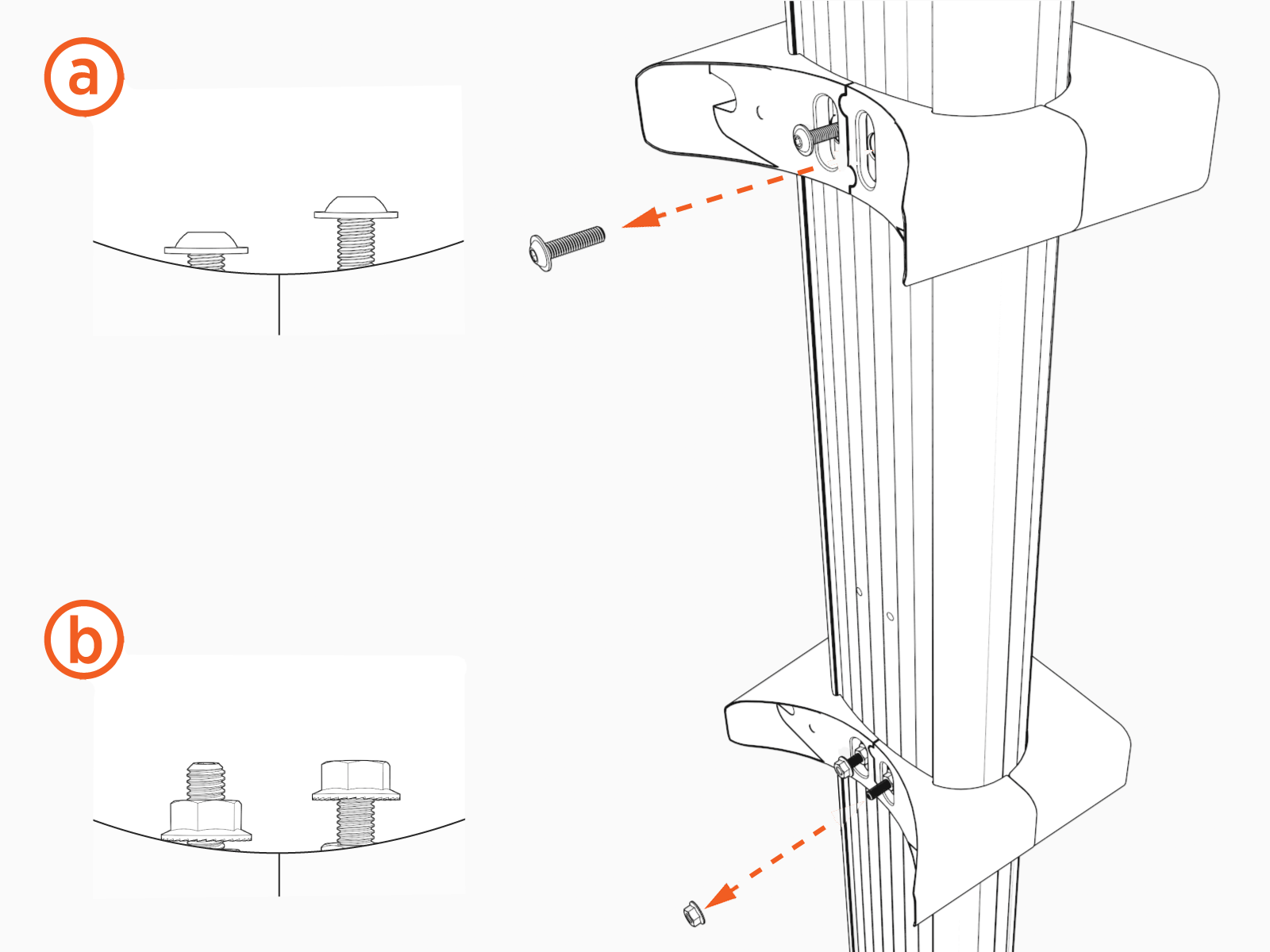
If the brackets needs to be replaced then follow the steps:
-
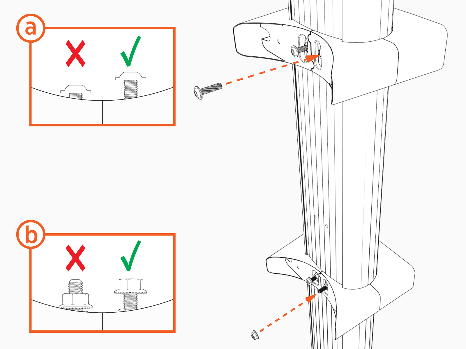
Remove the two flange bolts (a) from the upper bracket.
-
Remove the two threaded posts and nuts (b) from the bottom bracket.
-
REVERSE THE ABOVE STEPS TO REINSTALL THE WALL MOUNT HOUSING AND BRACKETS.
Replace a Wall Mount
Perform the following steps to replace a wall mount:
When installing a new wall mount housing, it is required to drill to create holes for the conduit. Follow the steps to replace a new wall mount housing.
-
Use the new wall mount and drill or use the knockouts in the housing to create holes for the conduit. If drilling holes, drill near the center of the lower housing plate.
(a) 33 mm (1.3 in) knockout
(b) 24 mm (0.95 in) knockout (optional Ethernet wiring)
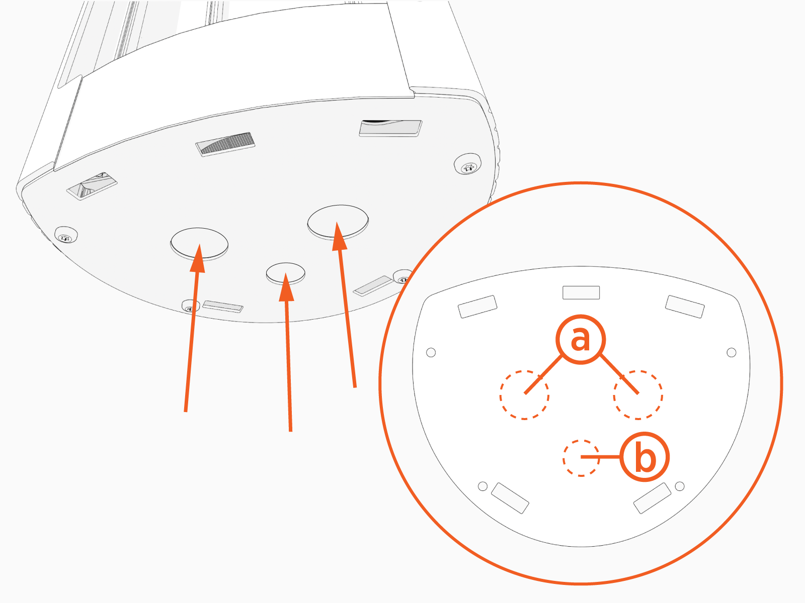
Maximum sizes for larger conduit:
-
Two 40 mm (1.5 in) conduits, 0.75 inch conduit (optional Ethernet)
-
One 68 mm (2.5 in) conduit, 0.75 inch conduit (optional Ethernet)
-
-
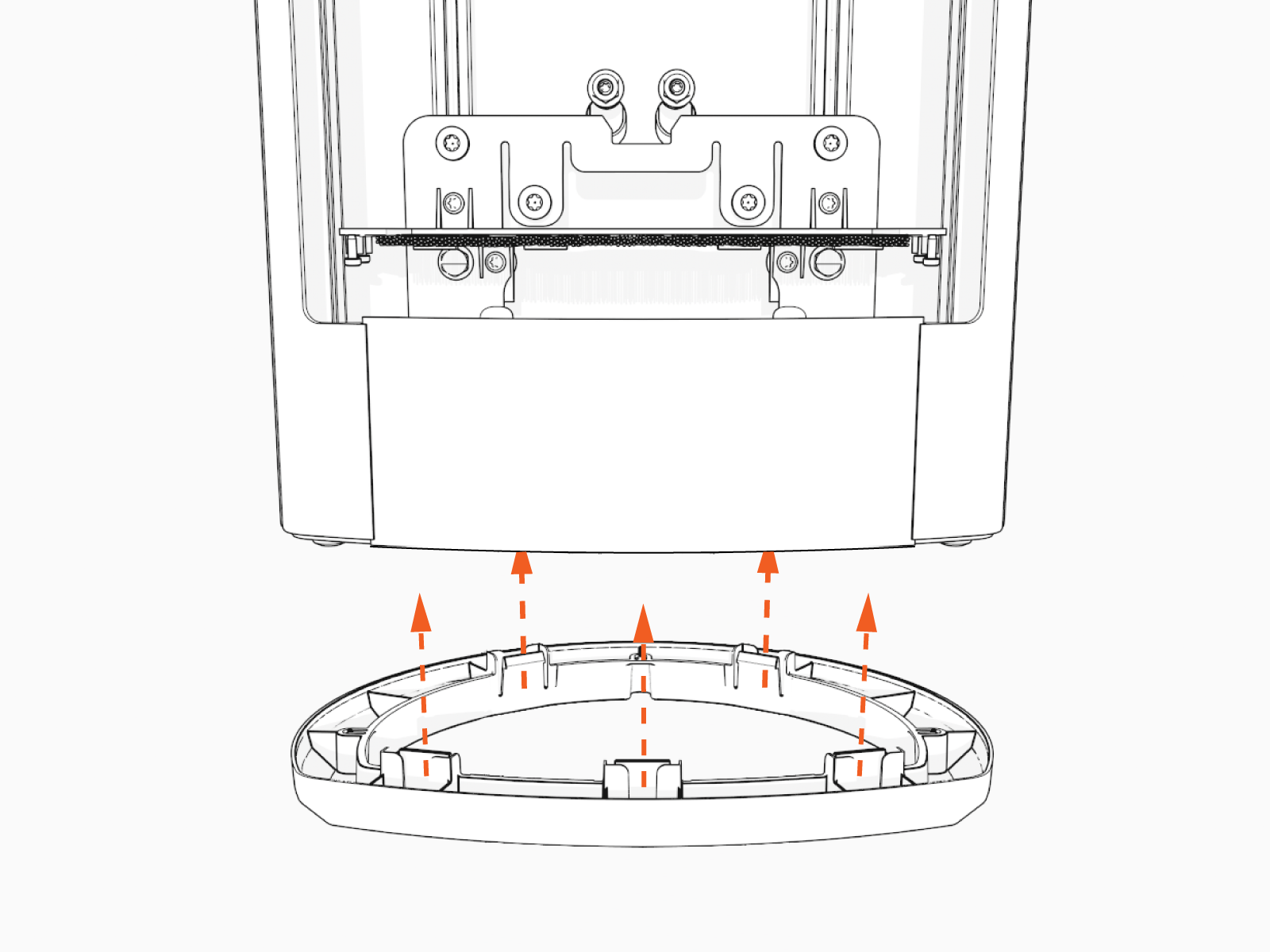
Snap lower bracket onto station.
Install the Housing
Perform the following steps to install the housing:
-
Insert two flange bolts (a) half way through the upper bracket.
-
Insert two threaded posts and nuts (b) on the bottom bracket.
-
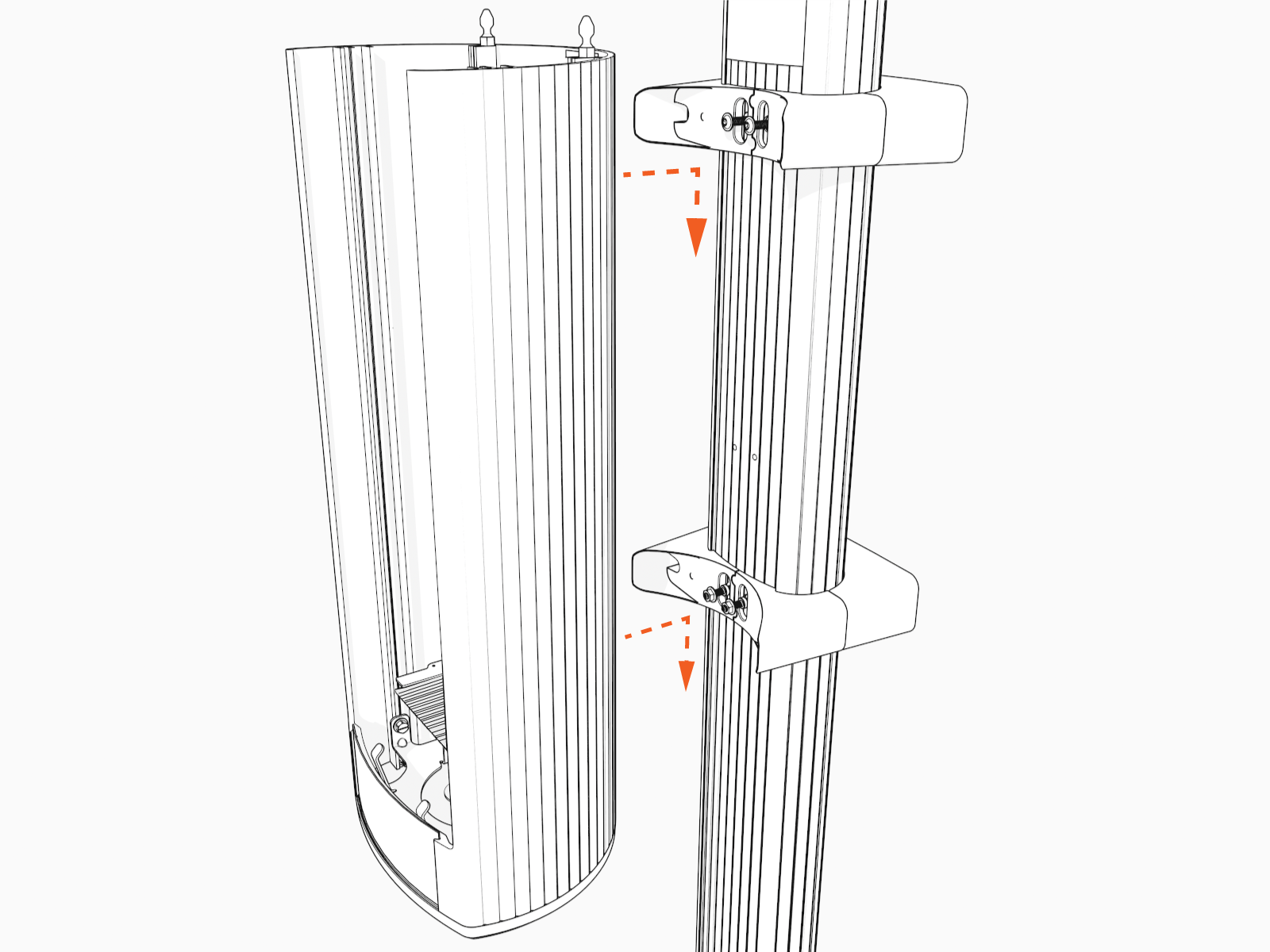
Align the mounting screws (top) and nuts (bottom) and hang the housing.
-
Use L-wrench or mini-rachet wrench to torque two flange screws (upper) and two preinstalled nuts (lower) to 5.7 Nm (50 in-lb).
Install the Conduit
Perform the following steps to install the conduit:
-
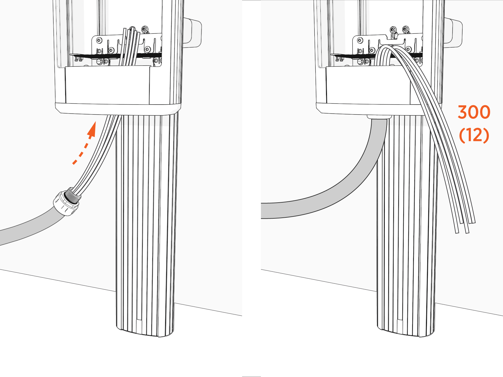
Feed conduit through the lower station bracket and into the station.
The length of wire available from the end of the conduit or the wall mount base must be at least 300 mm (12 in).
-
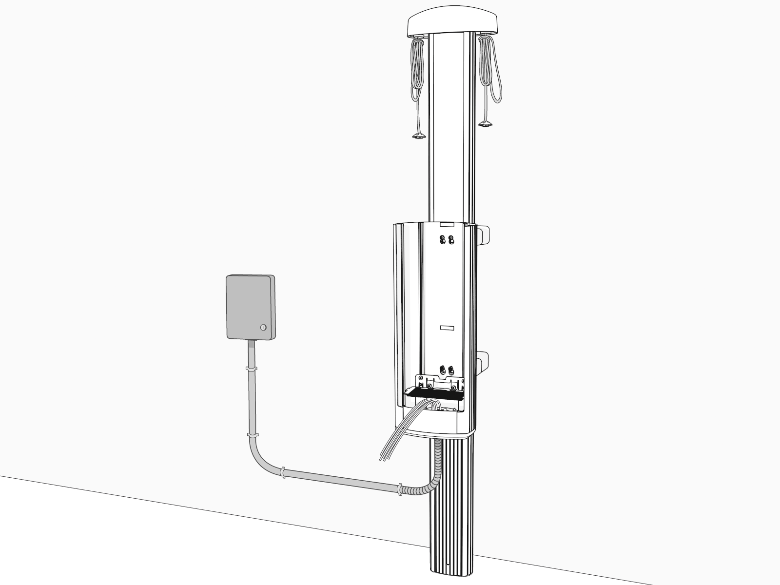
Select the appropriate gland or hardware and sealant, if applicable, to attach the conduit to the station.
Connect the Wiring
-
Strip the wires 30 mm (1-3/16 in).
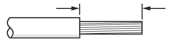 Cut wires straight across at 90° and not at an angle.
-
To open the center terminal block, insert an 8 mm (5/16 in) hex driver and rotate it counterclockwise. You might need to lift the label flap to access the terminal block.
Hold the driver in place to keep the terminal open while inserting the wire.
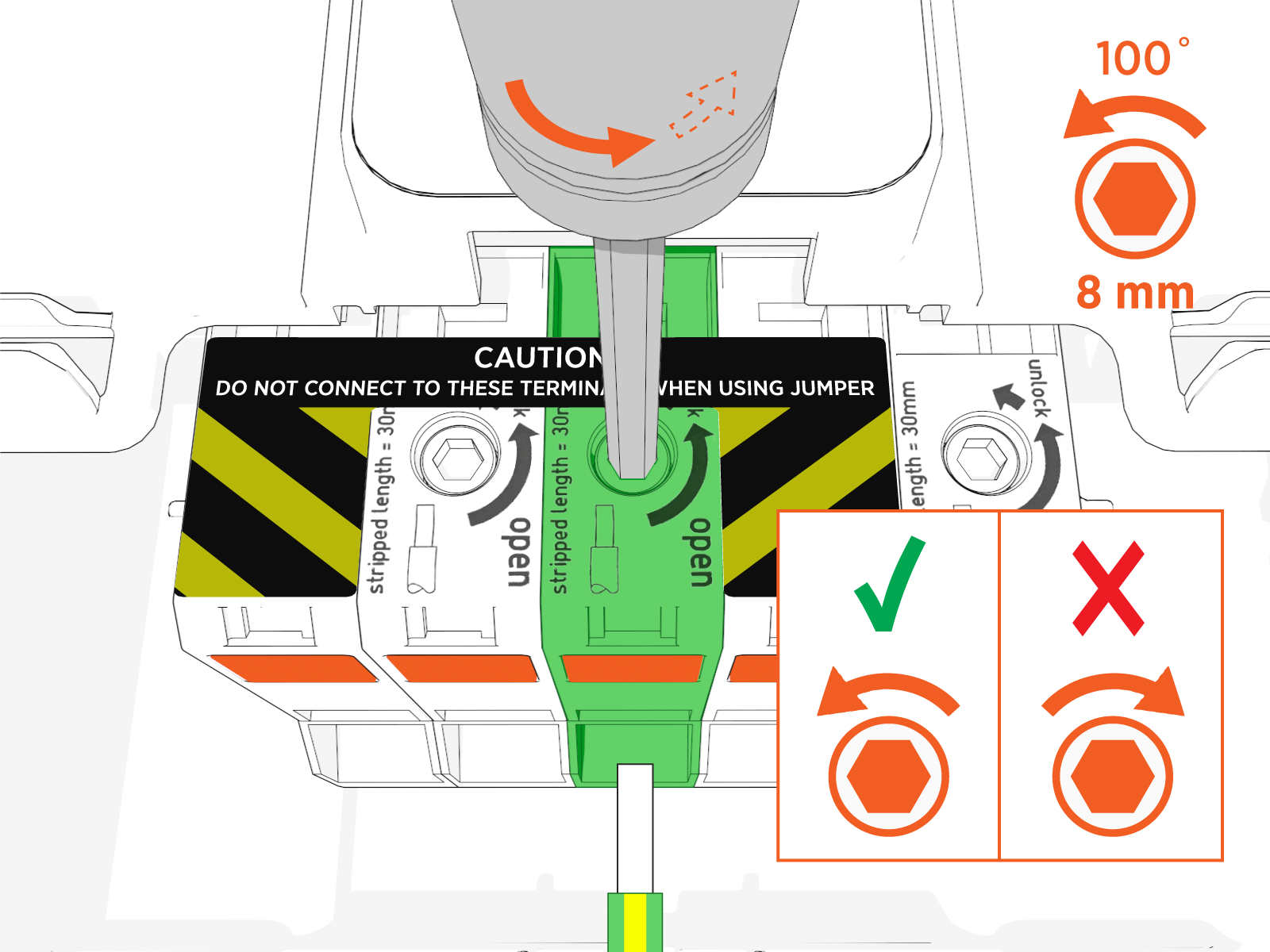
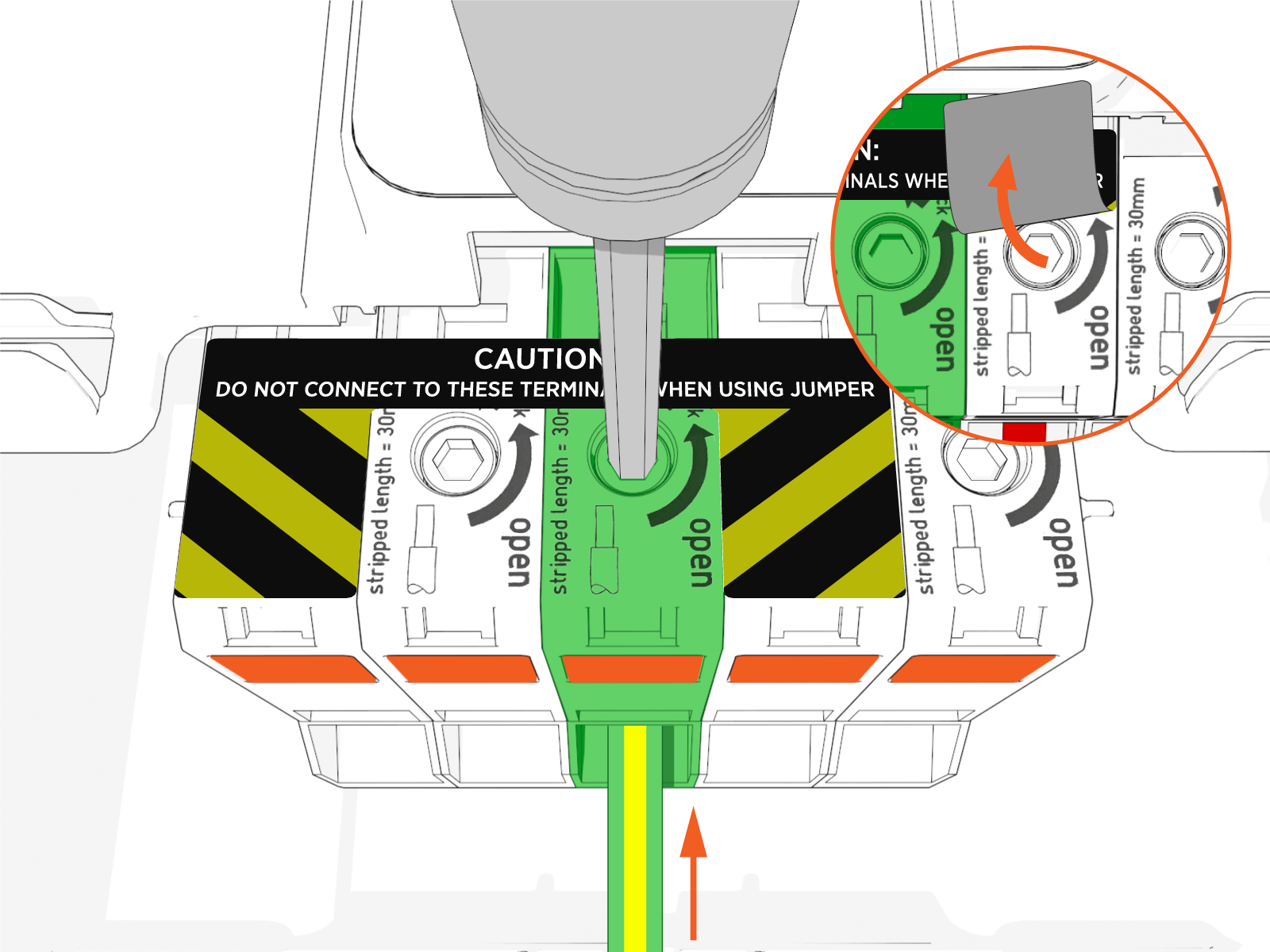 If you use the orange button to lock the terminal block in the open position, use only counterclockwise rotation to release it. Rotating the tool clockwise will damage the terminal block.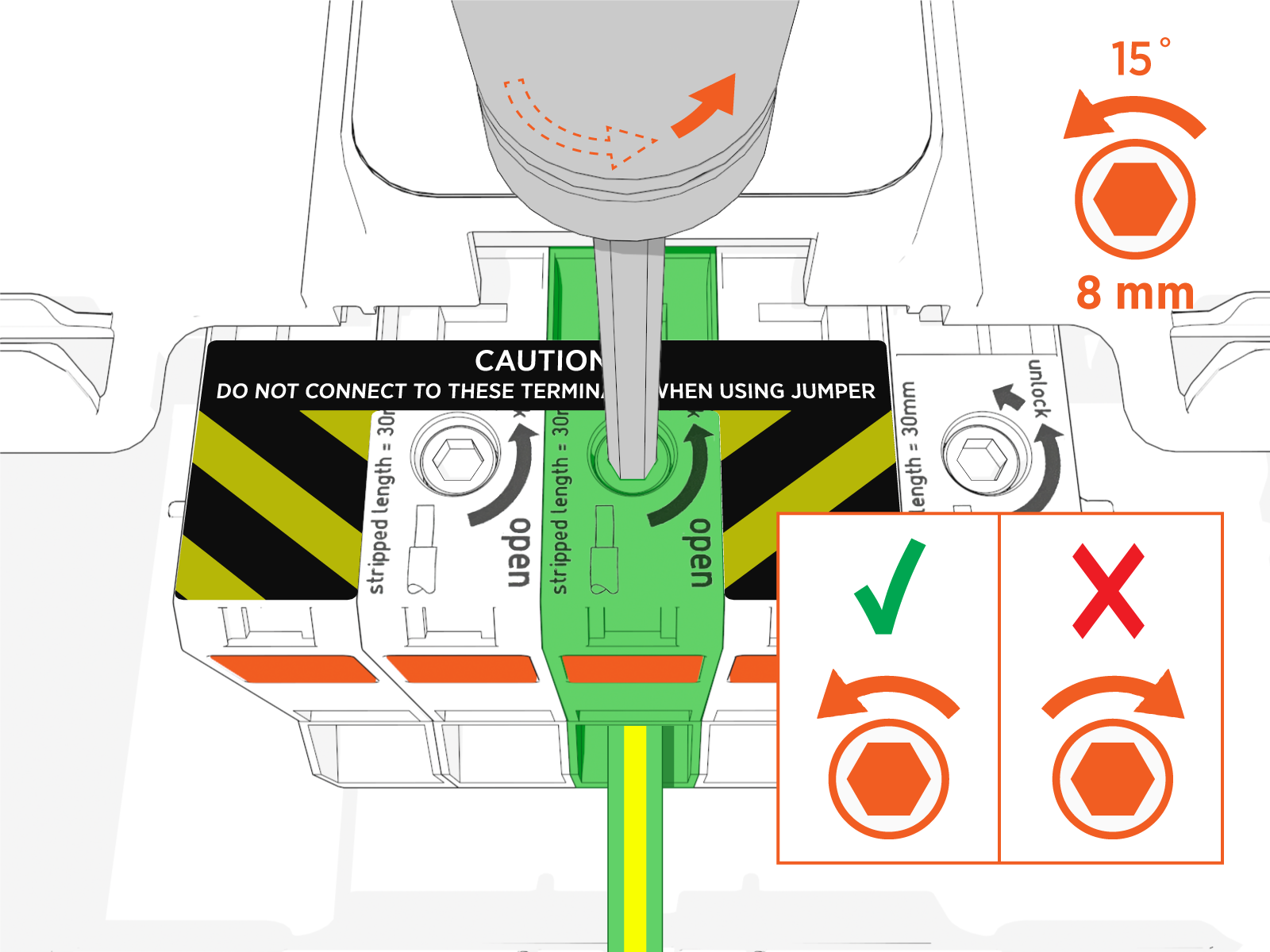
-
Insert the ground wire into the center terminal.
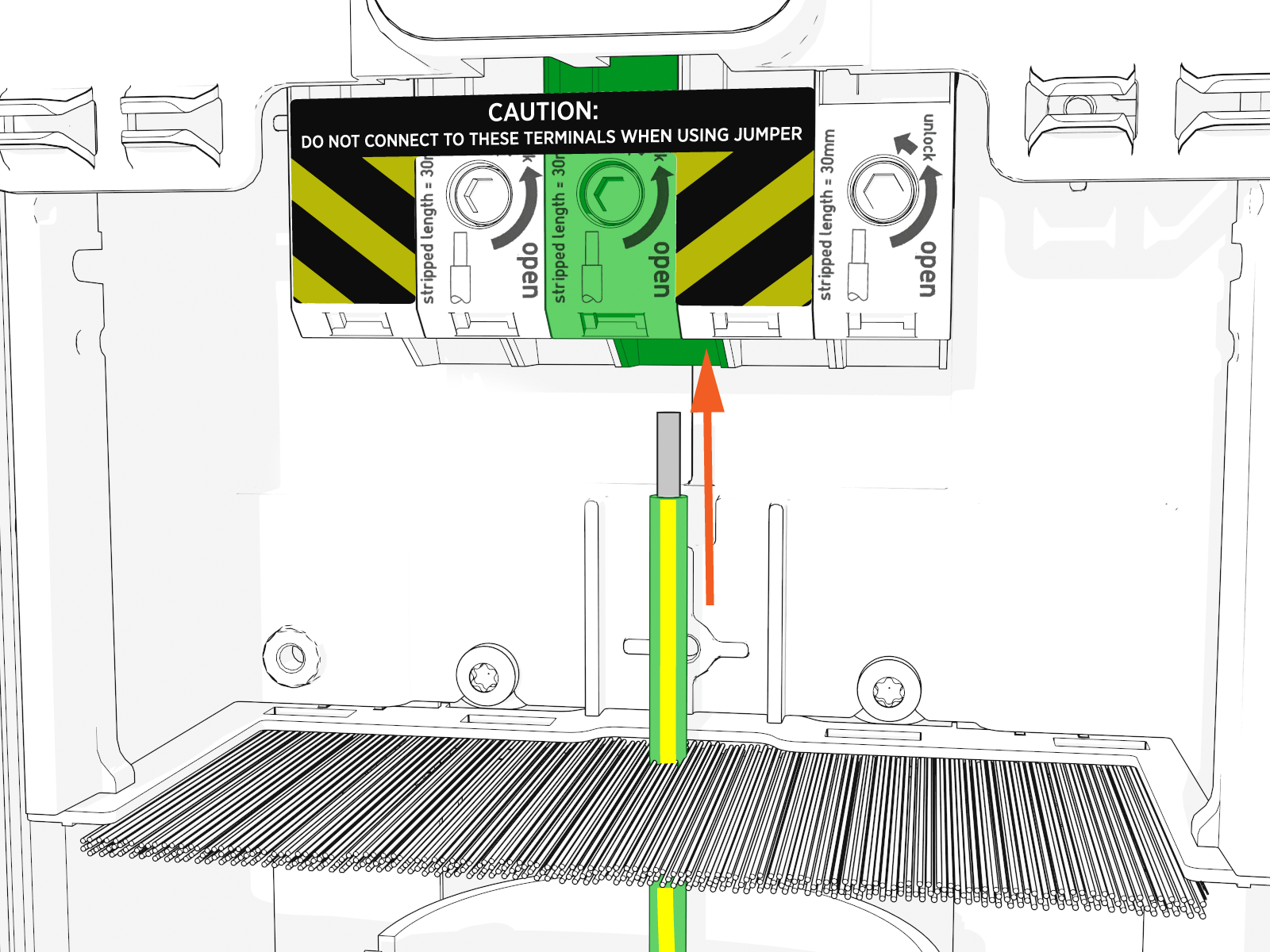
-
While holding the wire in place, release the hex driver to secure the wire in the terminal block.
-
Repeat previous steps for each wire.
-
Take a picture of the completed terminal block wiring with labels to submit during pinpointing.
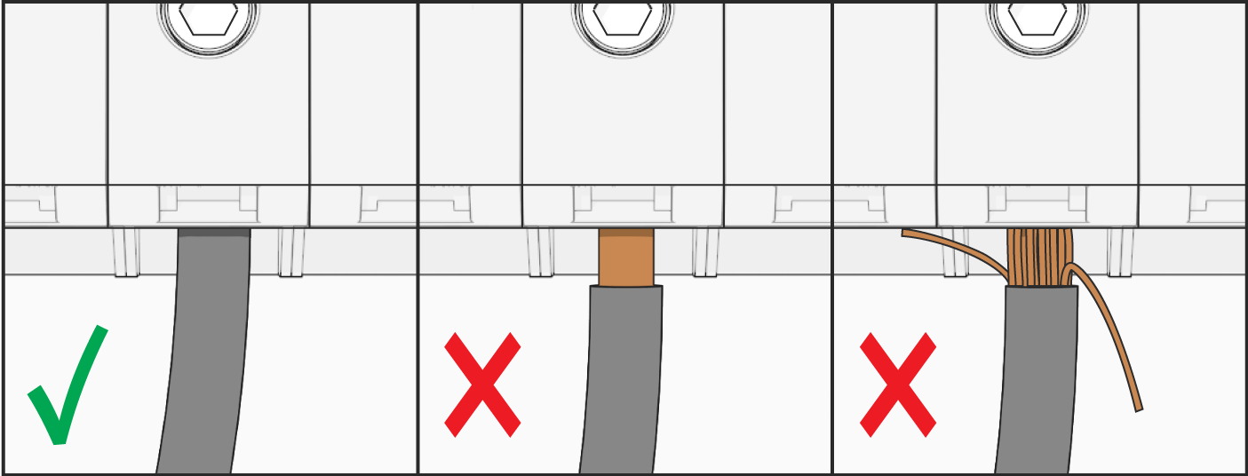
Ensure that you take a photo of the wires in the terminal block before continuing the installation process.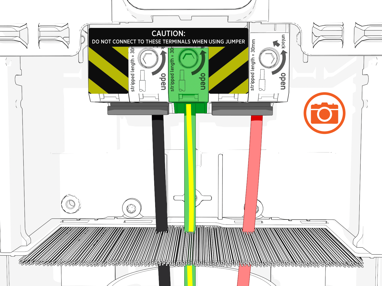 You should not see any copper wire outside the terminal block.