Replace the SIM Card
Required Tools and Materials
|
|
Torx screwdriver (T25) |
|
|
4 mm hex wrench
|
Remove the Head Assembly
To remove the Head Assembly, perform the following steps:
Risk of shock
-
Before any procedure, the technician must disconnect the power.
-
Follow local code to de-energize the applicable circuit and lock out/tag out the disconnect before proceeding. Use a multimeter to test that power is off.
-
Keep power off until the top cap is correctly reinstalled and the work is complete.
Failure to follow these instructions can result in serious injury, loss of life, or property damage.
Use the L-wrench to loosen two captive screws securing the top cap.

Remove the top cap.

-
Use the L-wrench to loosen, but do not remove, the screws securing the head assembly.

-
Lift head assembly and insert an L-wrench or a screwdriver through the hole on the side of the head assembly to hold the head assembly in the raised position.

Replace the SIM Card
To replace the pre-installed SIM card with the one taped to the station head unit, perform the following steps:
-
Remove the front lens by releasing the lens tabs, to find the SIM plug on the head assembly.
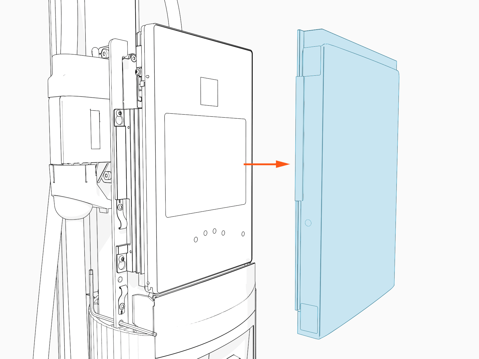
-
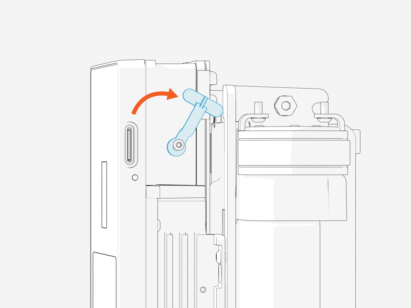
Lift the SIM plug located on the head assembly.
-
Gently PUSH the existing SIM card with a flat-head screwdriver to eject the SIM card from its slot.

-
Insert the notched edge of the SIM card into the slot with the notch facing upward. Slide it into the slot and use a corner of the SIM card's carrier or a tweezer to push it fully into the slot until it clicks into place.
Refer to the orientation instructions printed on the side of the head assembly.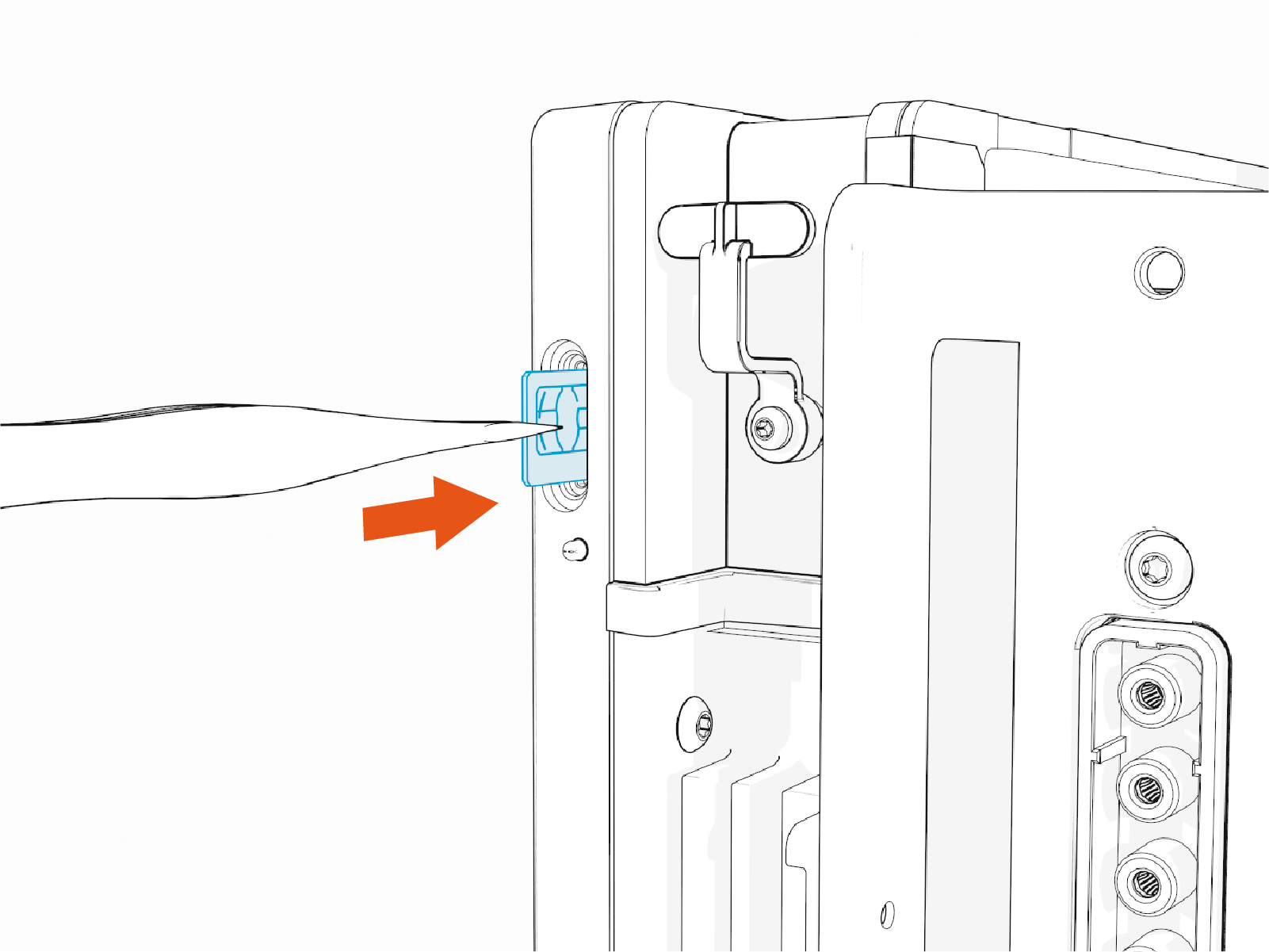
-
After securing the SIM card in place, return the SIM plug to its original position.
-
Reattach the front lens by aligning the lens tabs with the corresponding slots on the head assembly and pressing firmly until it snaps into place.

-
Remove the L-wrench.

-
Slide the head assembly all the way into the pedestal housing.

-
Ensure the head assembly is fully seated.

-
Using the L-wrench, tighten two screws.

Do not use an impact tool to tighten the screws.
-
Slide the top cap onto the head assembly, adjusting as necessary to clear the charging cables, until it fits into place.

-
Torque two captive screws to 1.1 Nm (10 in-lb).

Next Steps
Clear Lockout Faults
When you replace a part, the station triggers lockout faults.
To clear lockout faults, go to chargepoint.com/support and contact technical support using the appropriate region-specific number.
