Replace the EMV Chip Reader
To replace the EMV Chip Reader, perform the following steps:
Required Tools and Materials
|
|
Torx screwdriver (T25) |
|
|
4 mm hex wrench
|
Before You Begin
Remove the Charging Cables
To remove the Charging Cables, perform the following steps:
-
Use your ChargePoint card or the mobile app to wake the station up.
If the station does not have power, contact the station owner to learn when power will be available and discuss appropriate next steps.If you do not have a ChargePoint account, go to chargepoint.com/support, find your region's technical support number, and contact ChargePoint Support.
-
Unlock the charging cables and set them down gently.
-
Disconnect the power to the CP6000 at the service panel.
-
Before any procedure, the technician must disconnect the power.
-
Follow local code to de-energize the applicable circuit and lock out/tag out the disconnect before proceeding. Use a multimeter to test that power is off.
-
Keep power off until the top cap is correctly reinstalled and the work is complete.

Risk of shock
Failure to follow these instructions can result in serious injury, loss of life, or property damage.
Remove the Control and Communications Module (CCOM)
To remove the Control and Communication Module, perform the following steps:
-
Disconnect the power to the CP6000 at the service panel.
-
Before any procedure, the technician must disconnect the power.
-
Follow local code to de-energize the applicable circuit and lock out/tag out the disconnect before proceeding. Use a multimeter to test that power is off.
-
Keep power off until the top cap is correctly reinstalled and the work is complete.
-
Use the L-wrench to loosen two captive screws securing the top cap.

-
Remove the top cap.

-
Use the L-wrench to loosen, but do not remove, the screws securing the head assembly.

-
Lift head assembly. Insert an L-wrench or a screwdriver through the hole on the side of the head assembly to hold the head assembly in the raised position.

-
Unsnap the top and then bottom edges of the front lens and set it gently on a padded surface.

-
Loosen, but do not remove, the screws that secure the CCOM
 Control and Communications Module to the head assembly.
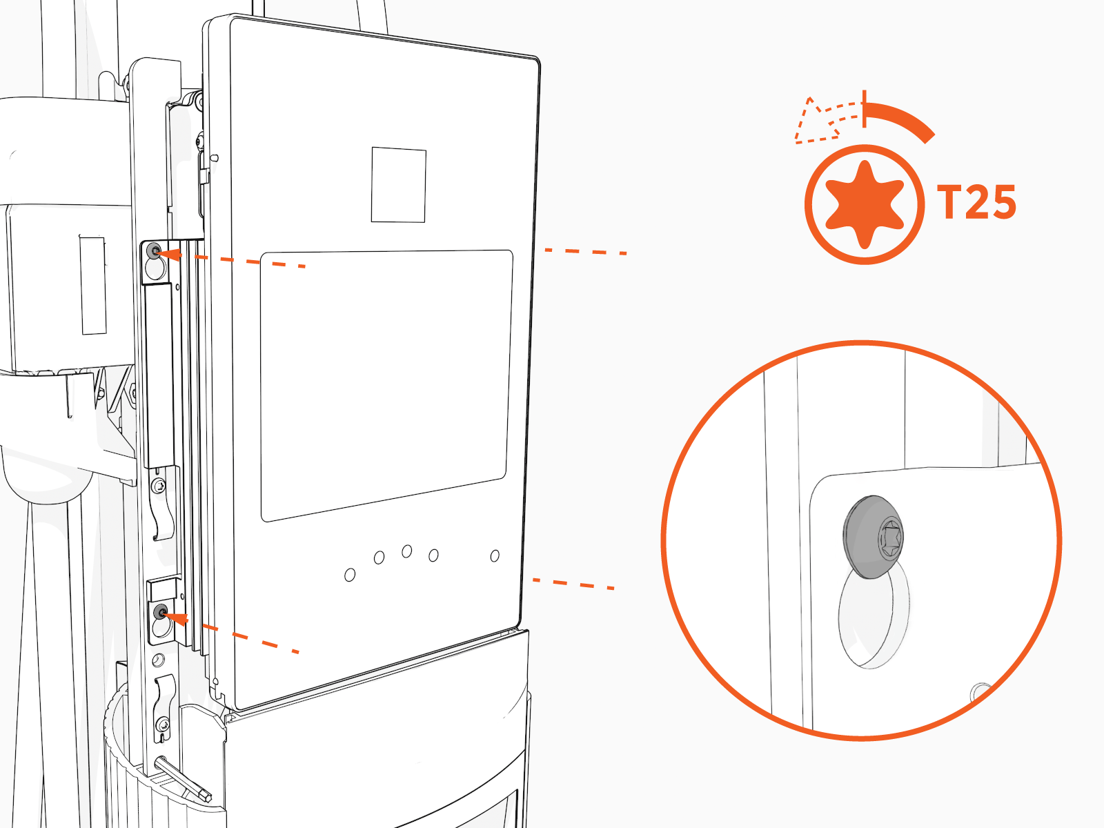
-
Lift the CCOM
Control and Communications Module up and tilt it away from the head assembly. The bottom edge of the CCOM
Control and Communications Module rests on the upper edge of the holster assembly.
-
Disconnect the RJ45 Ethernet cables from the CCOM
Control and Communications Module.
-
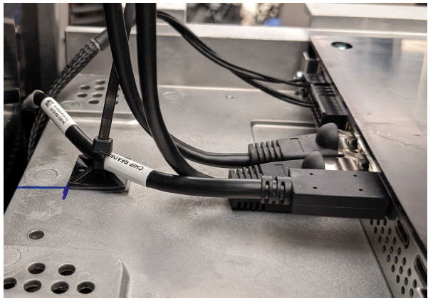
Cut the zip tie securing the USB
Universal Serial Bus-C cable, if present.
-
Disconnect the AC low-voltage and USB
Universal Serial Bus-C cables.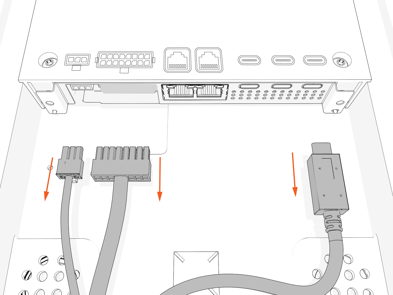
-
Unclip the hook and tether, remove the CCOM
Control and Communications Module, and set it aside.
Risk of shock
Failure to follow these instructions can result in serious injury, loss of life, or property damage.
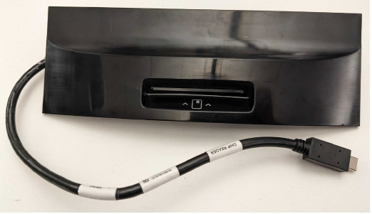
FRU Components
The EMV chip reader FRU![]() Field Replaceable Unit contains the chip reader with a cable for connecting to the CP6000.
Field Replaceable Unit contains the chip reader with a cable for connecting to the CP6000.
|
This FRU
|
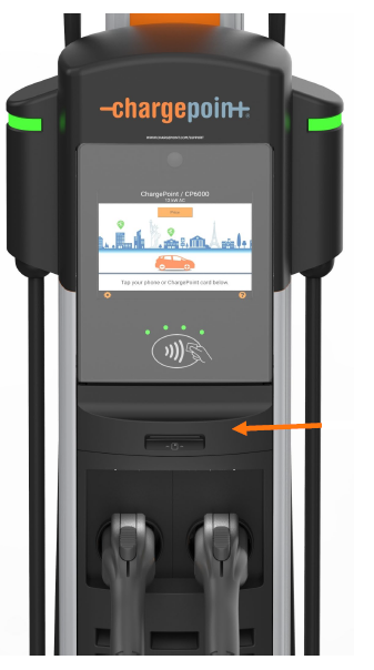
Replace Chip Reader
Remove Chip Reader Module
To remove Chip Reader Module, perform the following steps:
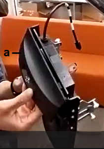
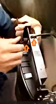
-
Remove the front cover of the chip reader module.
-
Front cover
-
-
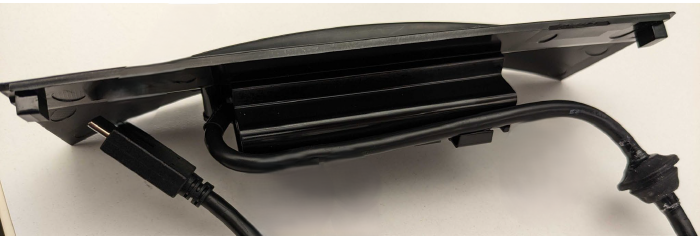
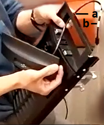
Pull down the USB
Universal Serial Bus-C cable through the grommet hole to remove the chip reader module.Push the grommet down to loosen it, then pull the USB Universal Serial Bus-C cable down through the hole.
-
Grommet hole
-
USB
Universal Serial Bus-C cable
Install a New Chip Reader Module
To install a New Chip Reader Module, perform the following steps:
Install Front Cover and USB-C Cable
To install a New Front Cover and USB![]() Universal Serial Bus-C Cable, perform the following steps:
Universal Serial Bus-C Cable, perform the following steps:
-
Insert the USB
Universal Serial Bus-C cable (from the new chip reader module) through the grommet hole. 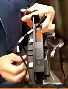
-
Pull the cable up until the grommet reaches the hole. Then push the grommet up until it is fully seated in the hole.
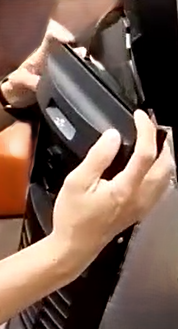
-
Attach the front cover by sliding it onto the frame until it snaps in place.
Reinstall CCOM
To reinstall the CCOM![]() Control and Communications Module, perform the following steps:
Control and Communications Module, perform the following steps:
-
Rest the CCOM
Control and Communications Module on the lower edge of the holster assembly.
-
Connect the hook and tether.

Connect the Cables
To connect the Cables, perform the following steps:
-
Connect the signal and the low voltage power cables.
-
Connect the RJ45 Ethernet cables from the smart cable assembly to the bottom of the CCOM
Control and Communications Module.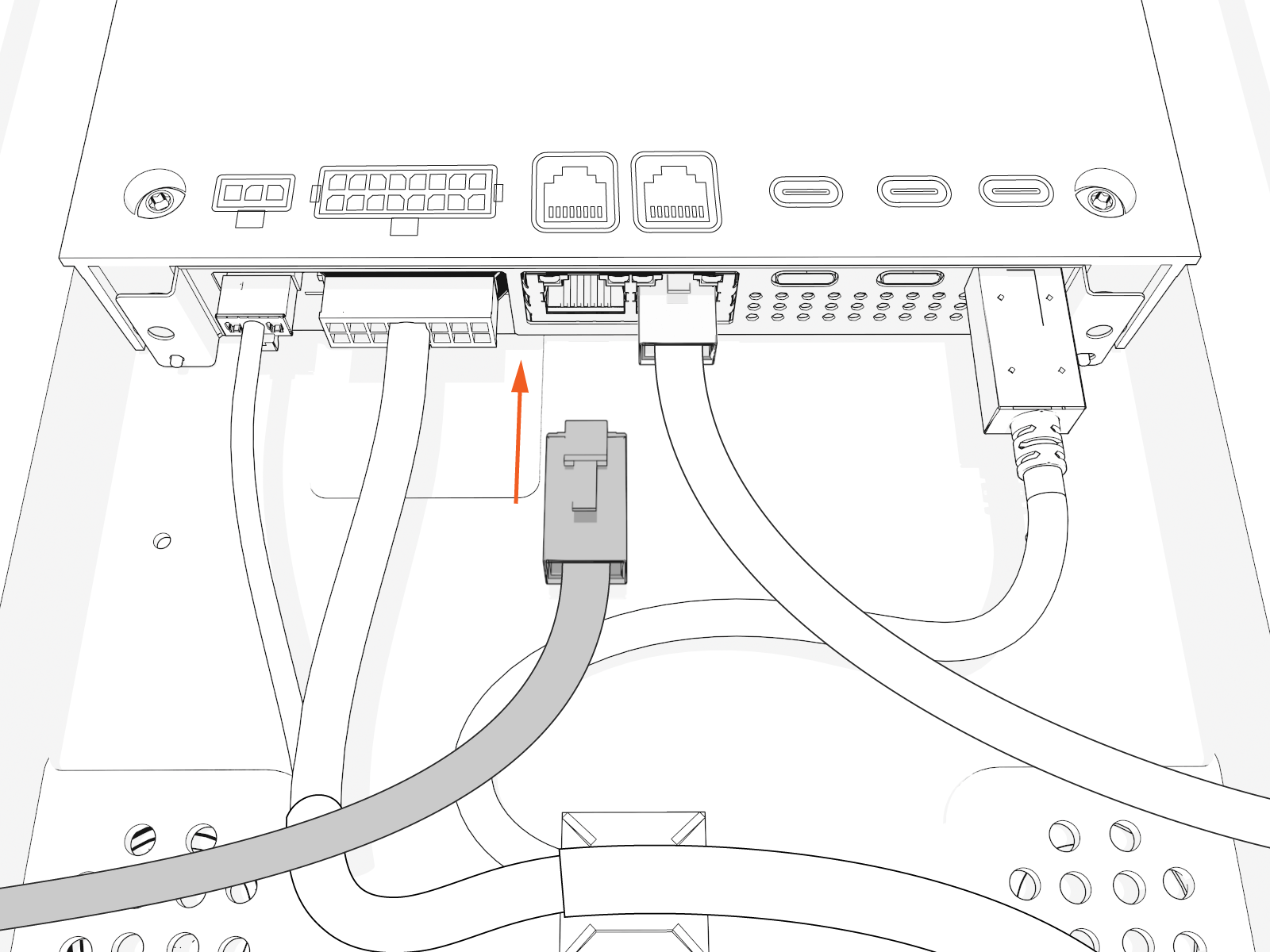
-
Connect the new USB
Universal Serial Bus-C cable from the chip reader module to one of the USB Universal Serial Bus-C ports. -
Use a zip tie to secure the USB
Universal Serial Bus-C cable.
-
Raise the CCOM
Control and Communications Module and slide it into place on the head assembly. 
-
Use four screws to secure the CCOM
Control and Communications Module. Tighten the screws to 1.7 Nm (15 in-lb).
-
Snap the bottom and then top edges of the front lens onto the head assembly.

-
Remove the L-wrench.

-
Slide the head assembly all the way into the pedestal housing.

-
Ensure the head assembly is fully seated.

-
Using the L-wrench, tighten two screws.

-
Slide the top cap onto the head assembly, adjusting as necessary to clear the charging cables, until it fits into place.

-
Torque two captive screws to 1.1 Nm (10 in-lb).

-
At the electrical panel, power up the station.
One or both port LEDs appear Red until the lockout faults are cleared.