Install Overhead-Mount Power Link 1000
Follow these instructions to anchor, install, and wire each Power Link 1000 onto a wall or gantry.
Disconnect Power
To disconnect power, complete the following steps:
- Before any procedure, disconnect the power.
- Follow local code and site lockout/tagout procedure to de-energize the station.
- Wait for energy to dissipate (approximately five minutes).
- Keep power off until all covers and panels are reinstalled and the work is complete.
-
Disconnect power at the site electrical panel.
Follow standard practice and local code to de-energize the applicable circuit and lock out/tag out the disconnect before proceeding.
-
Use a multimeter to test that the unit is de-energized.
Install and Secure to the Mounting Plate
To install and secure to the mounting plate, complete the following set of steps:
Mark Location
To mark location, complete the following steps:
-
Use a multimeter to test each DC conductor for continuity.
-
If not already done, pull service wiring through the wall or conduit as described in the Express Plus Site Design Guide.
-
Measure the distance above grade that the Power Link 1000 will sit.
Check your specific site plans and the Site Design Guide to ensure the Power Link 1000 mounting location meets clearance specifications above ground to comply with ADA regulations and above grade to comply with flood regulations. -
Use the mounting plate as a template to determine position. Measure position and ensure level placement. Mark the mounting holes.
-
Consult site plans for any site-specific requirements.
-
Attach the mounting plate to the surface. Install six M8 bolts or studs spaced 400 mm (16 in) center to center.
Torque to the specification indicated in the site plans.
Contractor provides fasteners. Site plans must specify fasteners appropriate for and rated to secure the weight to the material.
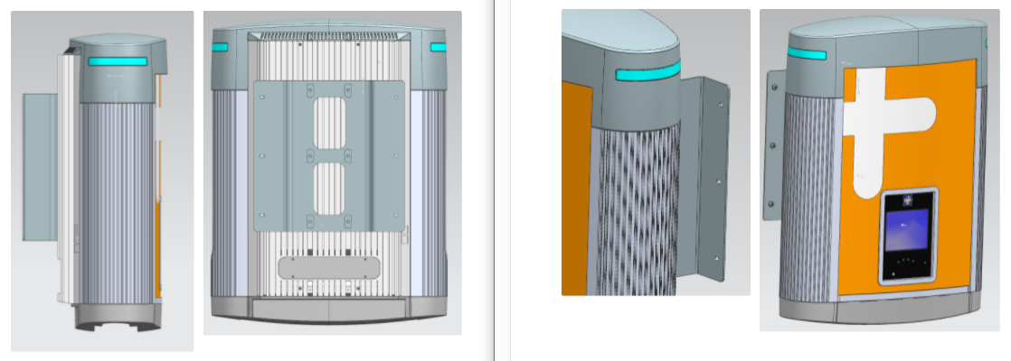 Align the vertical center of the mounting plate with the wiring that enters from the ground or rear of the installation site.
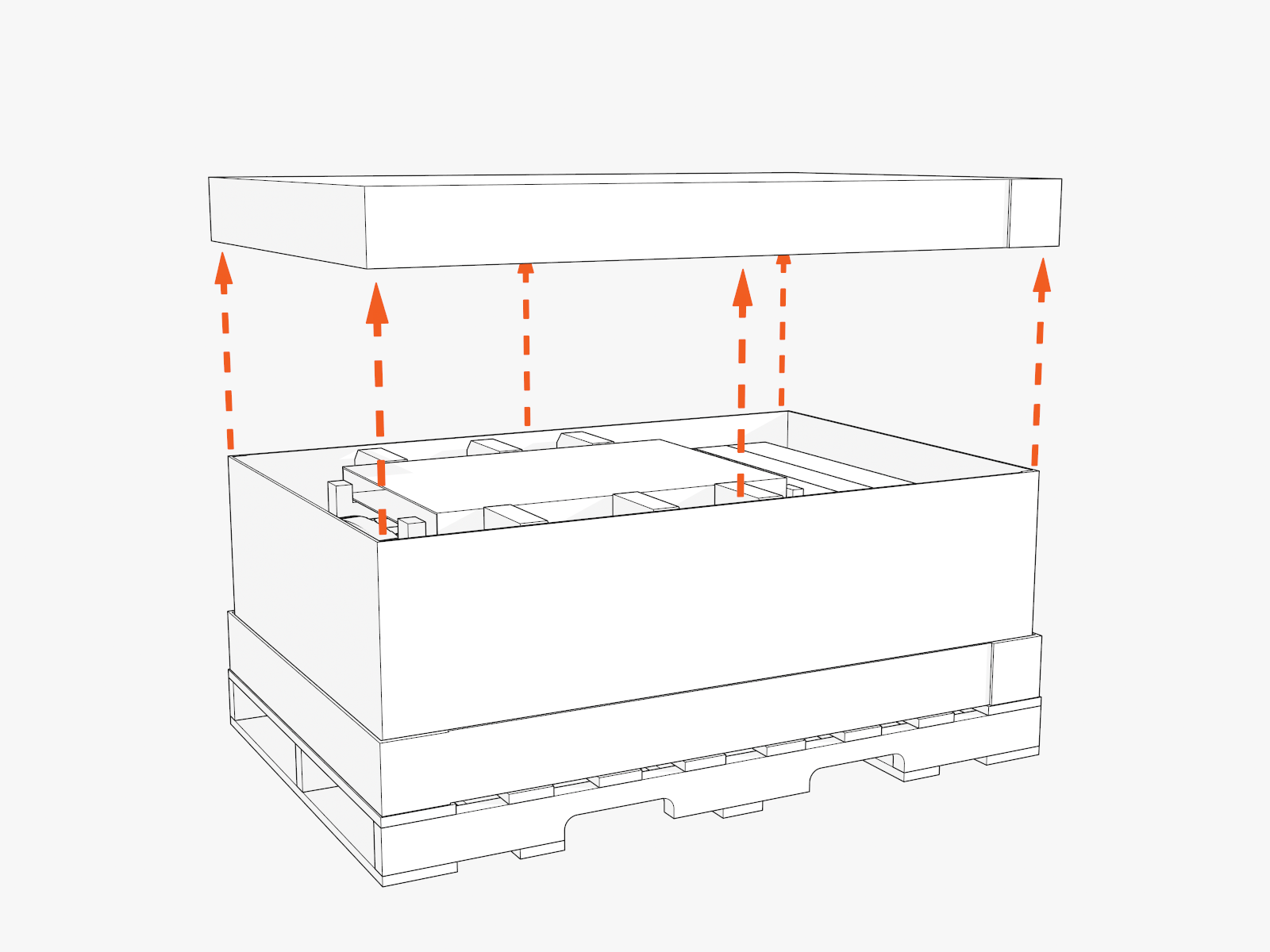
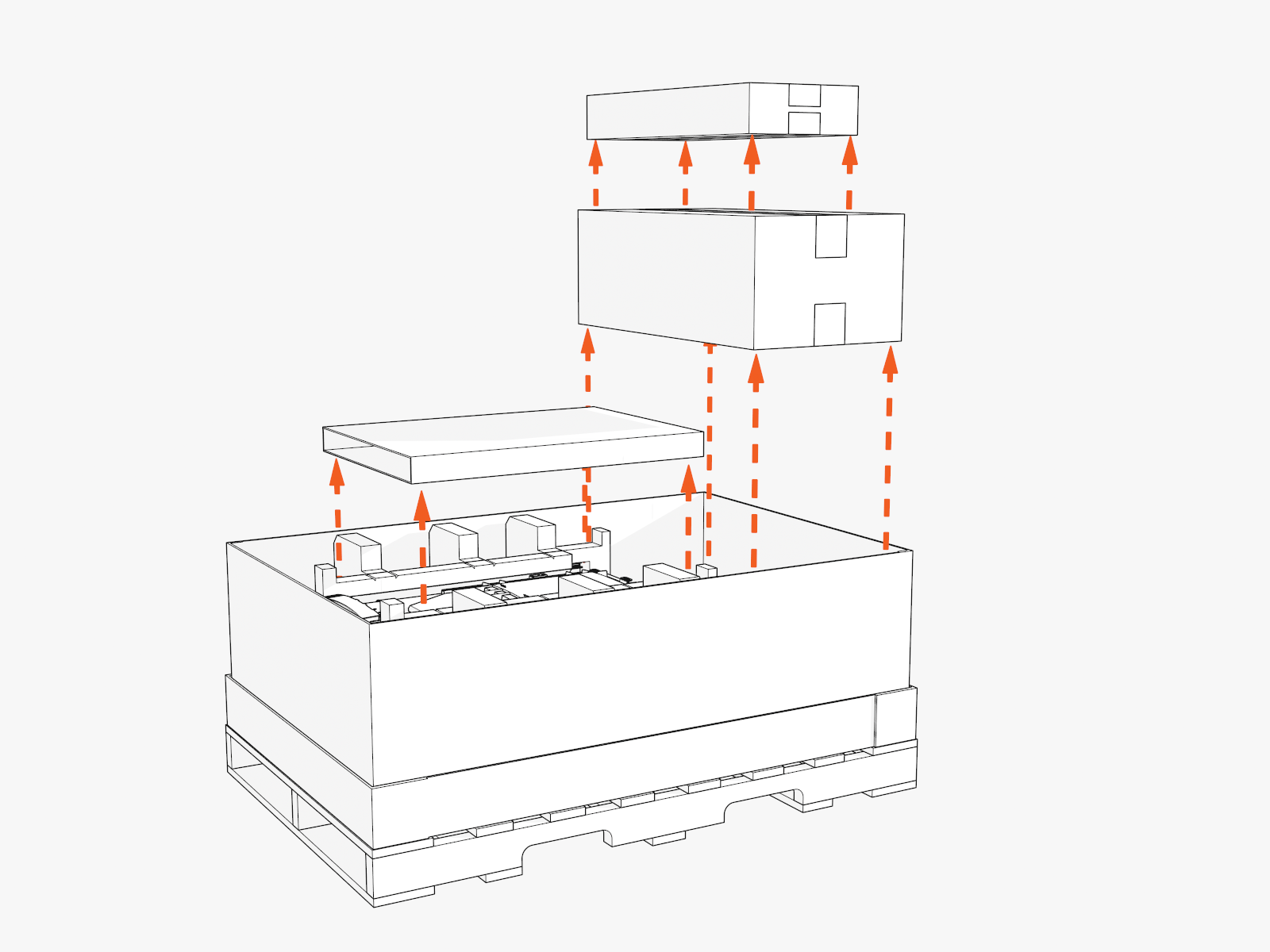
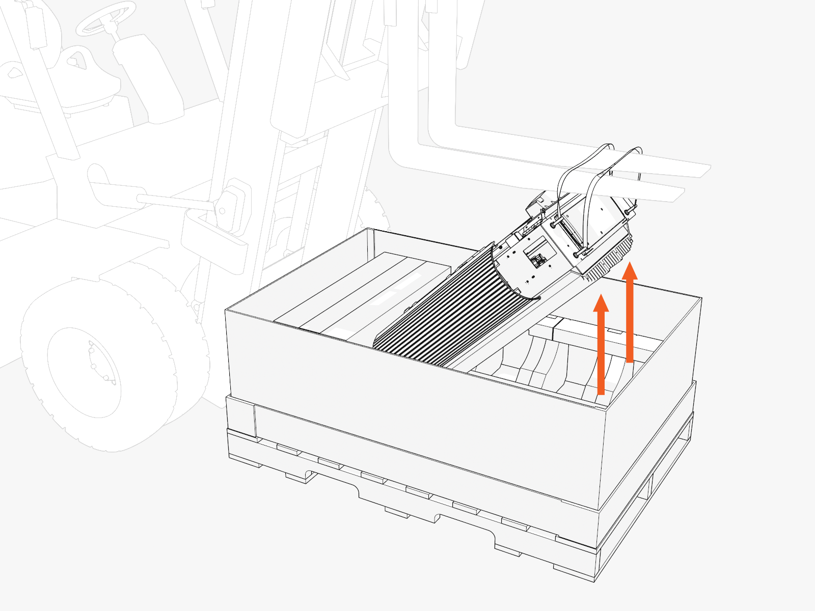
Unpack
To unpack, complete the following steps:
-
Lift off the crate cover.
-
Set aside the separate packages that are inside the crate.
These packages contain vinyl signs, trims, and top cover to be installed later.
-
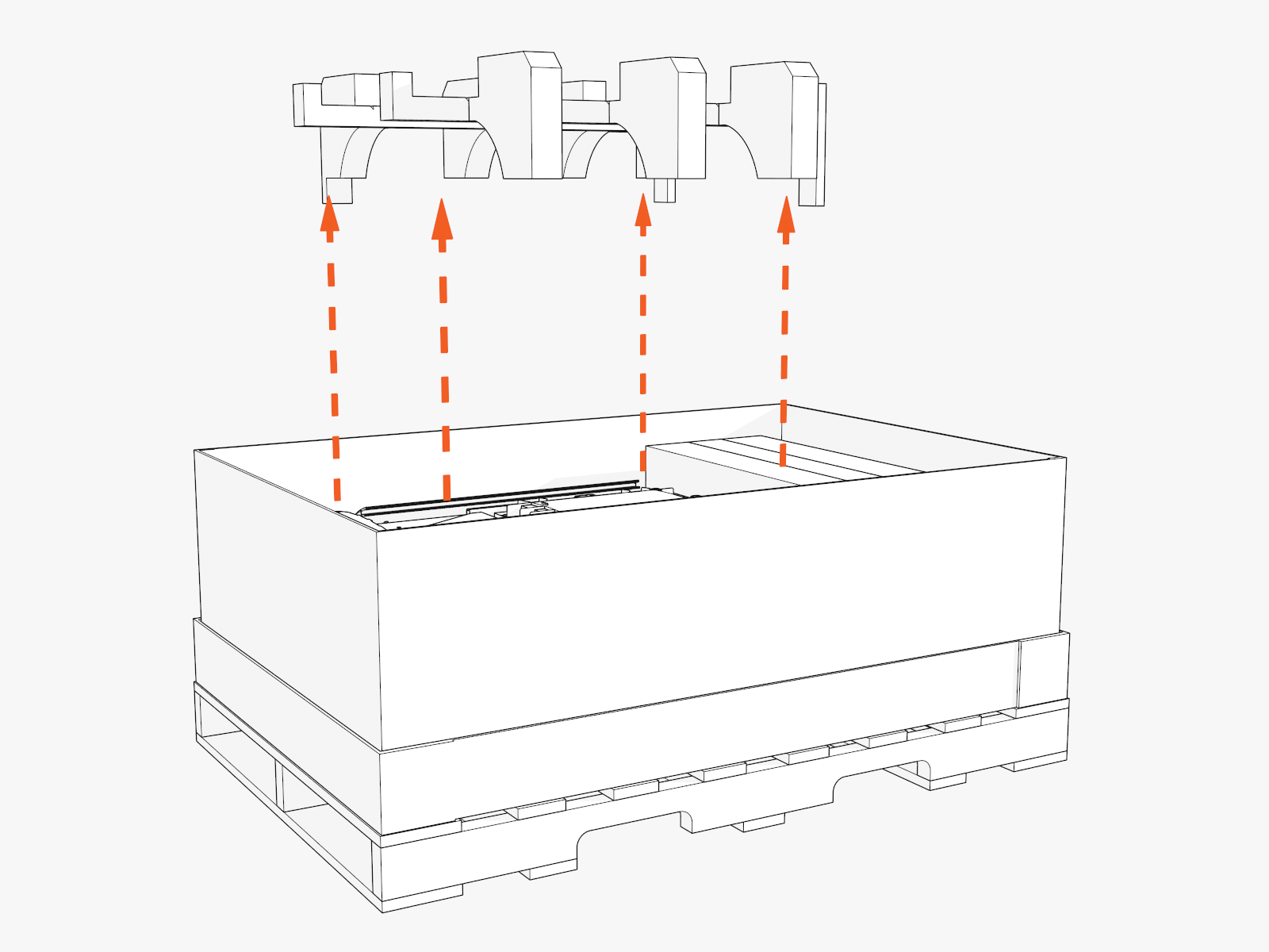
Remove the top foam inserts.
-
At the top of the Power Link 1000, locate four preinstalled eye bolts and lifting straps.
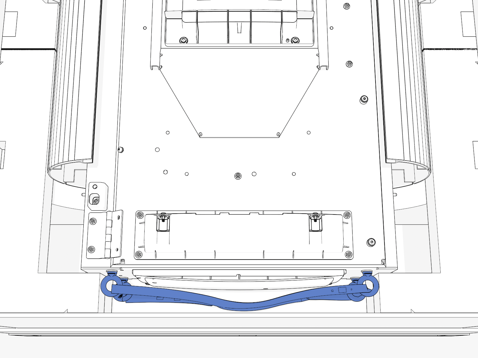
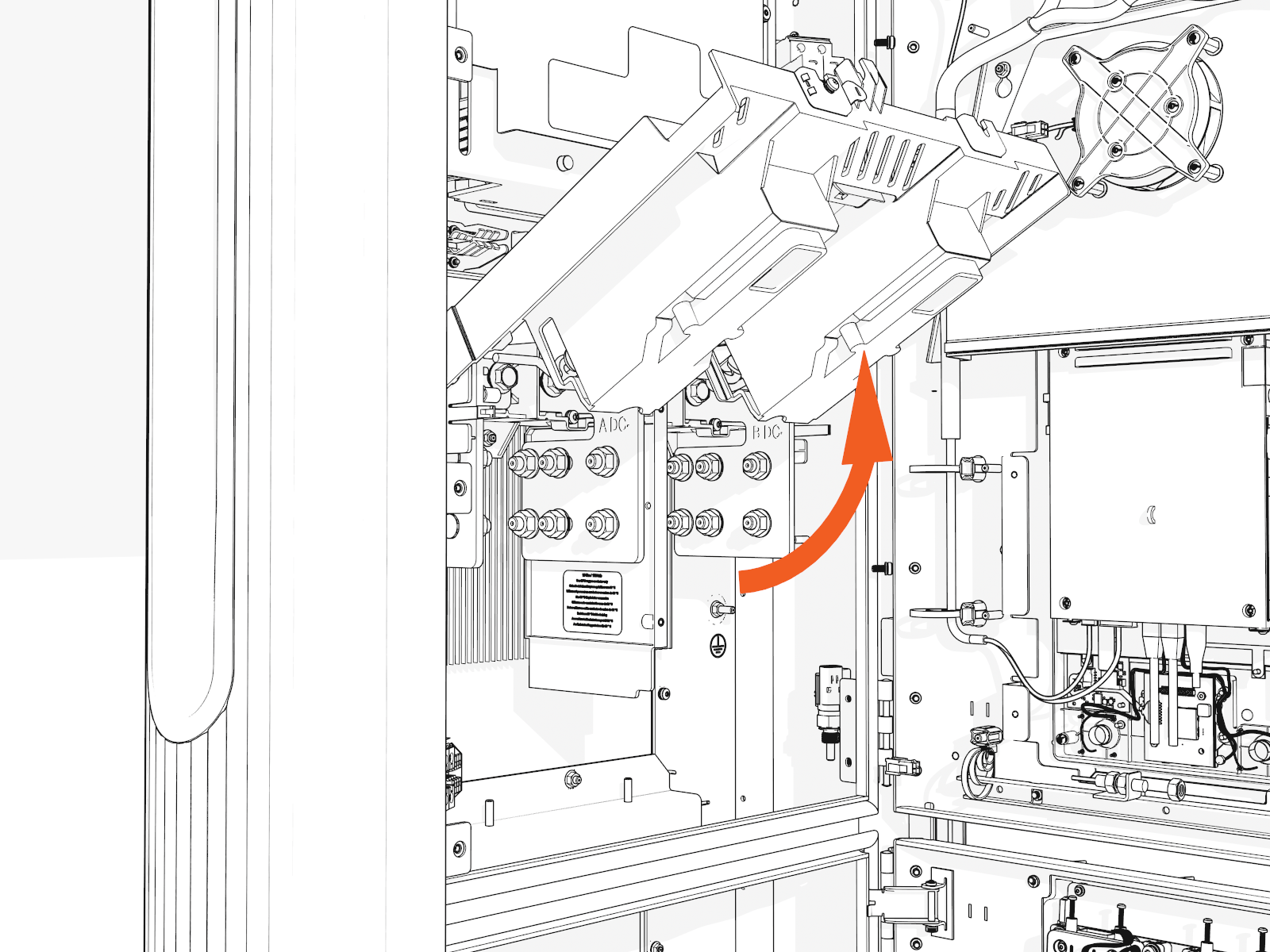
Access Inside
To access inside, complete the following steps:
-
Lift up the Power Link 1000 by the lifting straps.
Use a forklift or service cart with retaining straps.
-
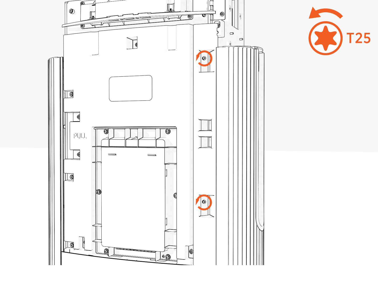
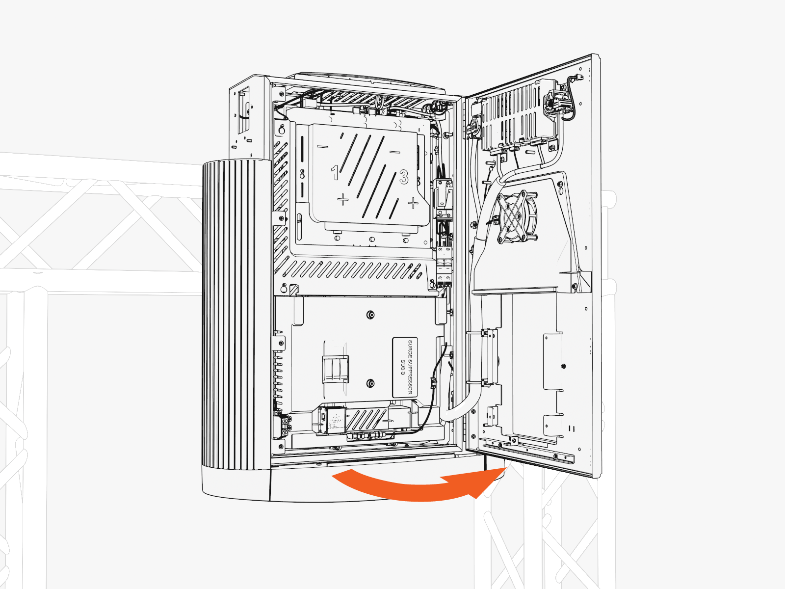
Loosen the two screws from the door bracket (only if covers are B. Install Vinyl Signs, Trims, and Top Cover).
Hold the middle of the door bracket. Lift and tilt out.
-
Uninstall the four screws along the left side to open the door.
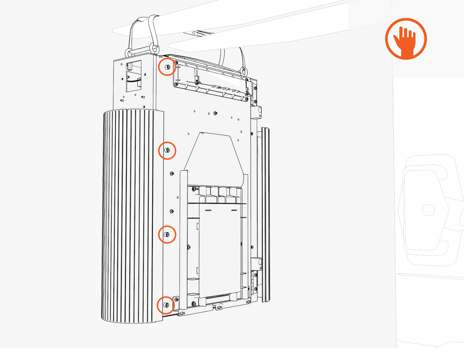
-
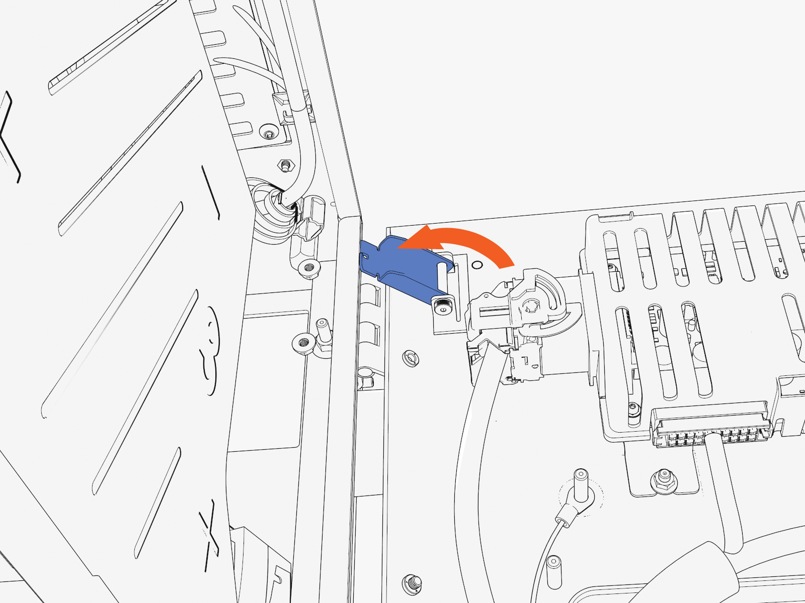
At the hinges inside the door, rotate the orange-colored wind stops into the door gap (to prevent the door from accidentally closing while you work).
Gland Plate
To create openings in the gland plate for the wiring, complete the following steps:
-
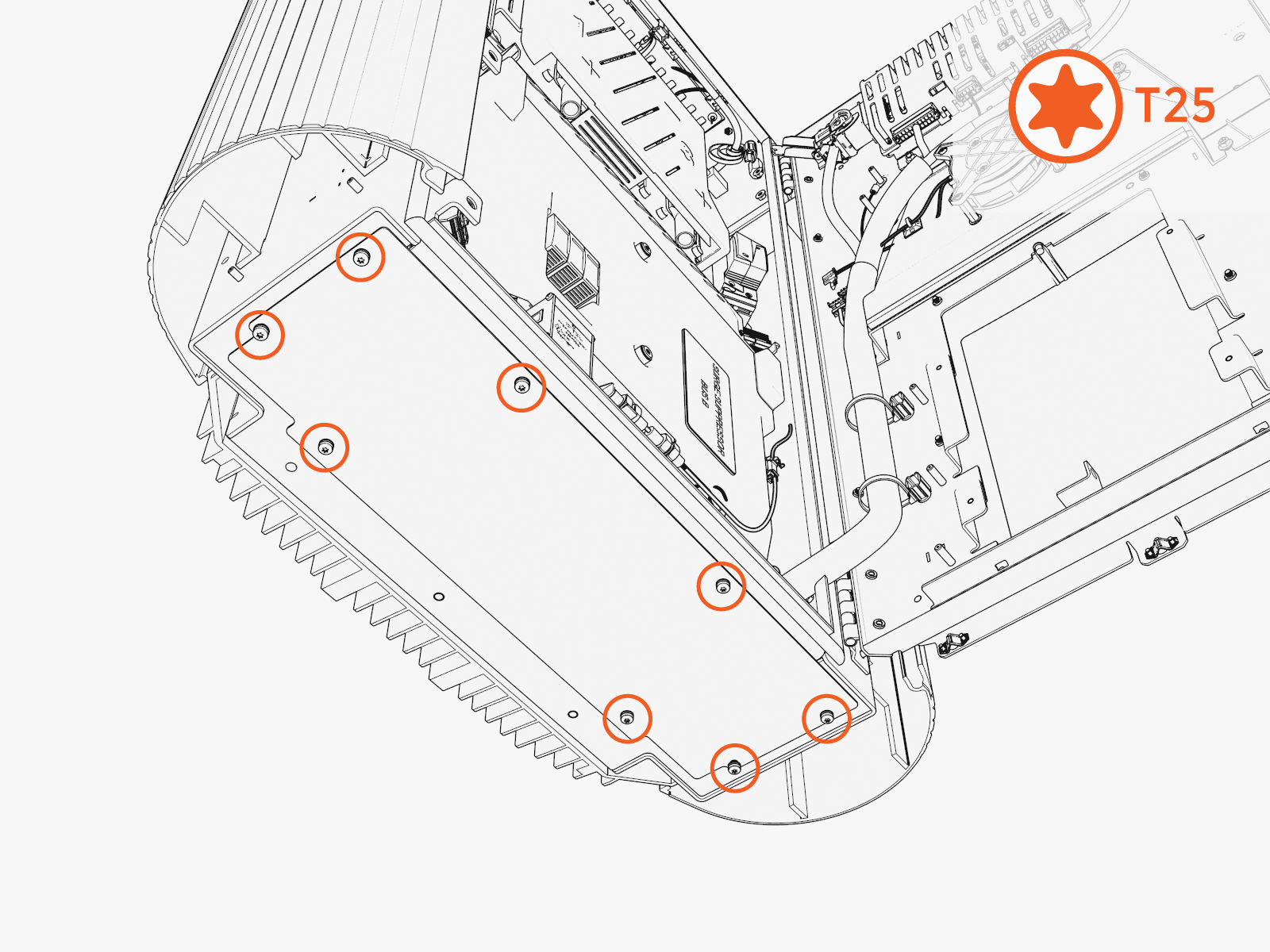
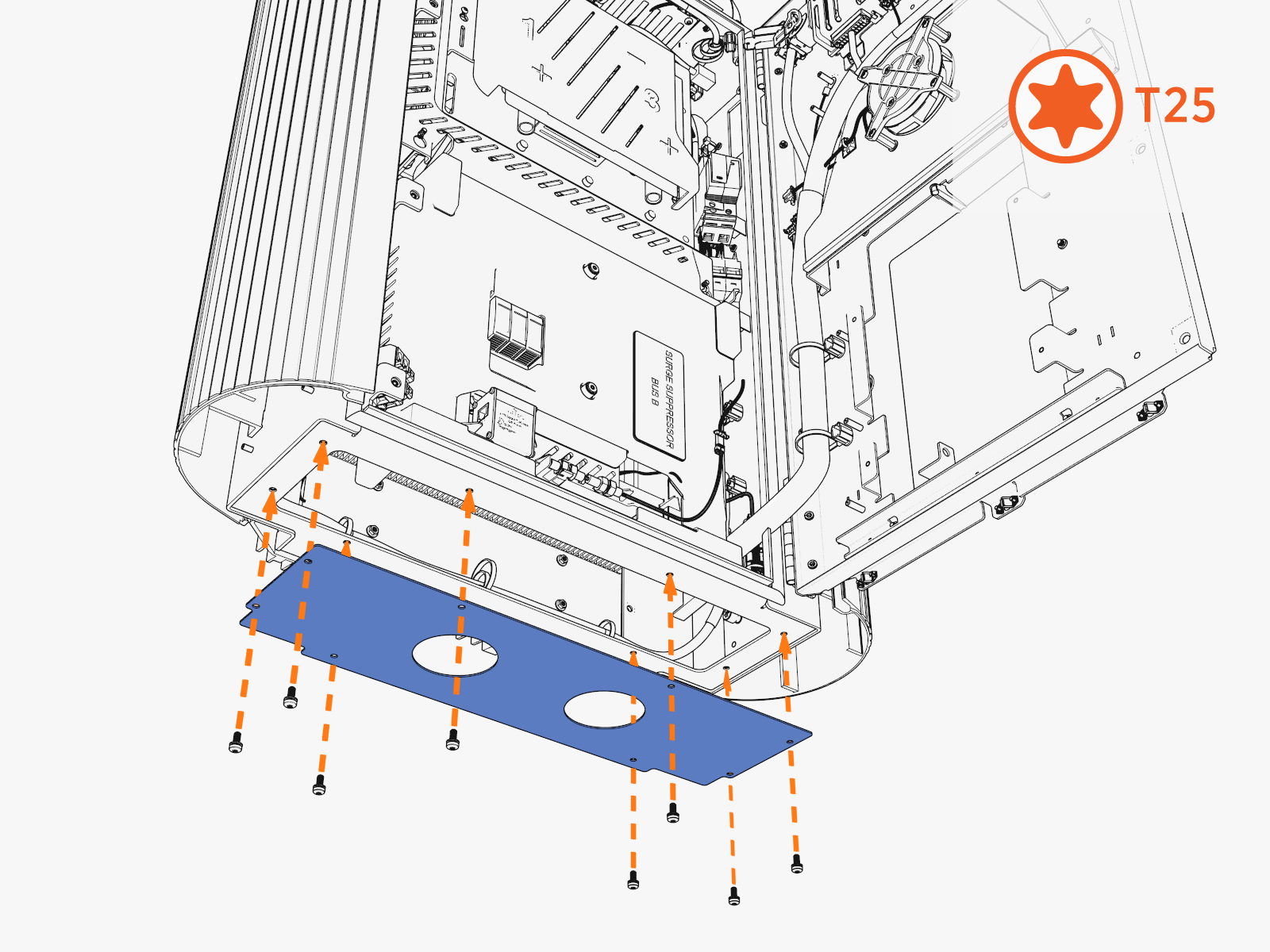
Uninstall the screws from the gland plate located at the bottom.
-
Remove the gland plate.

-
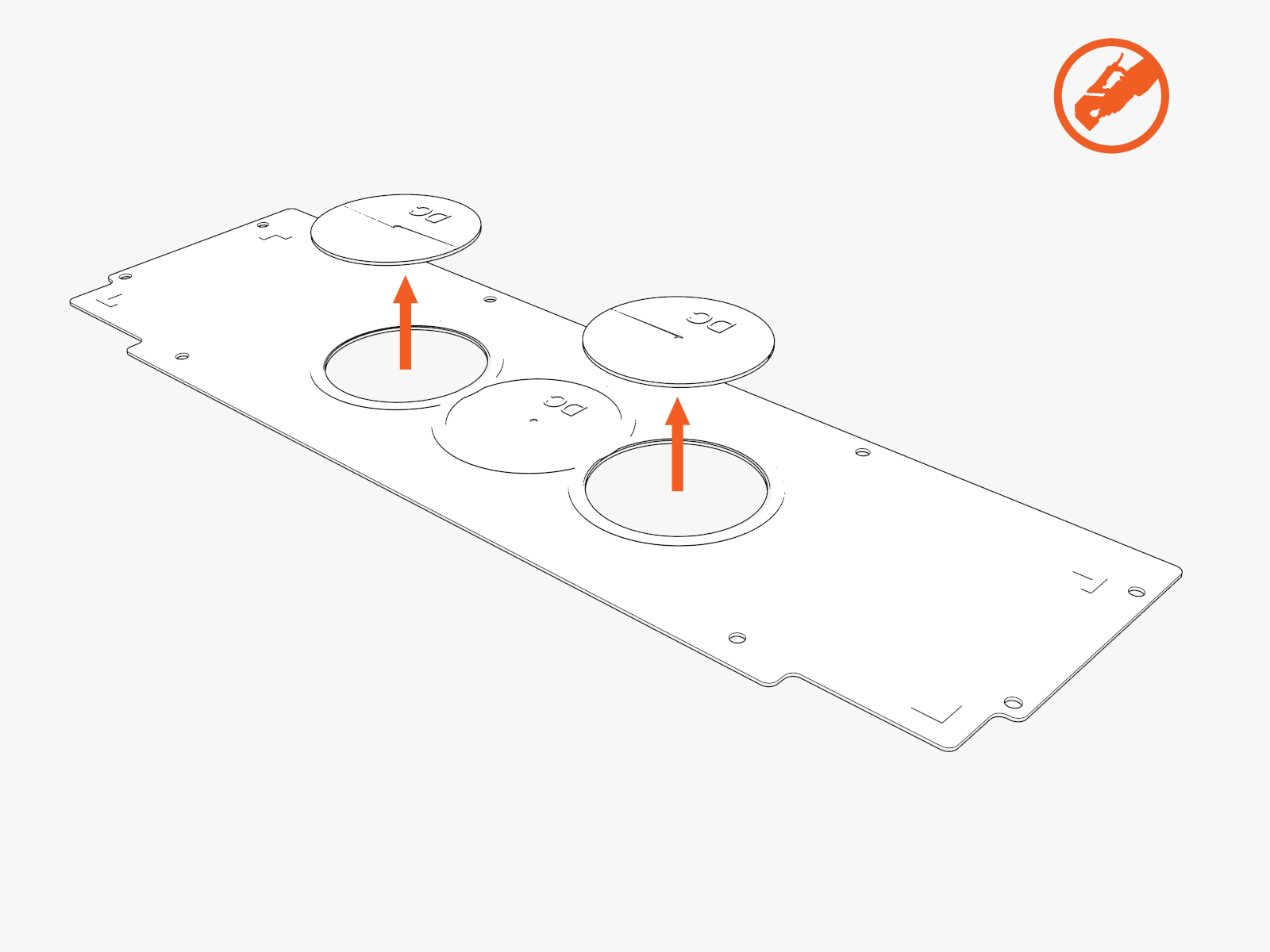
Use a hydraulic hole punch to create openings in the gland plate for this wiring:
-
DC input conduits
-
Check if the site plans require one or two DC conduits.
-
Use the gland plate pilot holes as a guide.
-
Punch out one or two DC opening(s).
-
-
48 V DC and Ethernet conduits
-
Check if the site plans require one, two, or three conduits.
-
Punch out the correct number of 48 V DC and Ethernet opening(s).
-
-
-
Reinstall the gland plate.
Mount
To install the mount, complete the following steps:
-
Disengage windstops and close the door. Install screws into the door.
-
Move the wiring out of the way.
-
Install the wall mount bracket onto the back of the Power Link 1000.
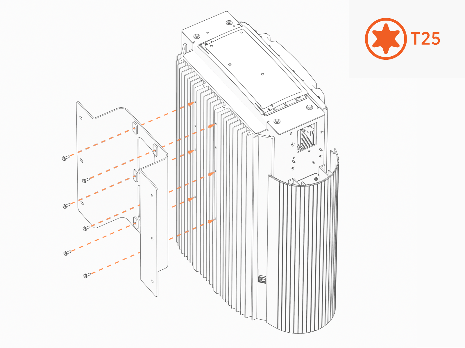
-
Attach the wall mount plate onto the bracket. Install fasteners called for by the site plans.
Torque to the specification indicated in the site plans. Mount as preferred.Contractor provides fasteners. Site plans must specify fasteners appropriate for and rated to secure the weight to the material.
-
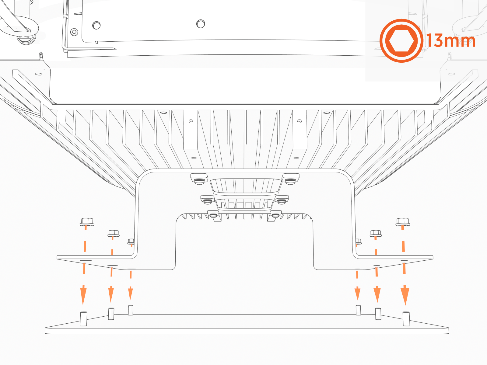
Remove the four outer screws from the gland plate (if previously reinstalled).

-
Use those screws to install the bottom cap.
-
Disengage windstops and close the door. Install screws into the door.
-
Reopen the door.
-
Route the wiring through the bottom.
 Ensure that there is (a) 12 mm (1/2 in) clearance between the bottom cap and the conduit.
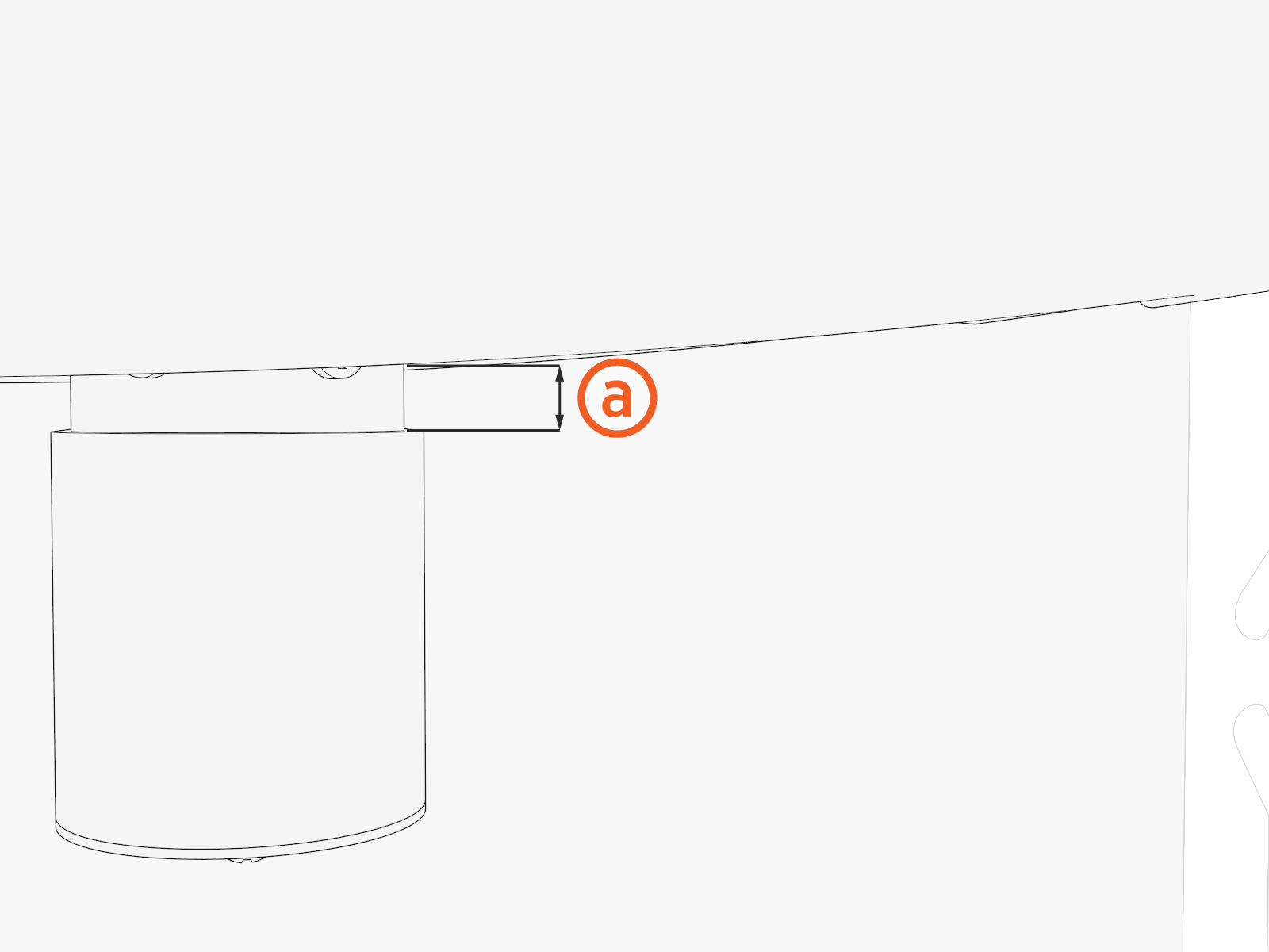
Connect the Wiring
To connect the wiring, complete the following steps:
- Before any procedure, disconnect the power.
- Follow local code and site lockout/tagout procedure to de-energize the station.
- Wait for energy to dissipate (approximately five minutes).
- Keep power off until all covers and panels are reinstalled and the work is complete.
-
Disconnect power at the site electrical panel.
Follow standard practice and local code to de-energize the applicable circuit and lock out/tag out the disconnect before proceeding.
-
Use a multimeter to test that the unit is de-energized.
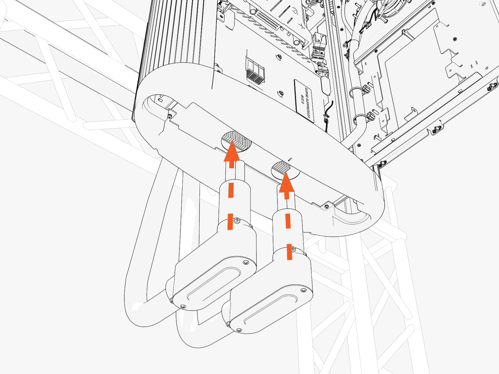
Access the bus bars
To access the bus bars, complete the following steps:
-
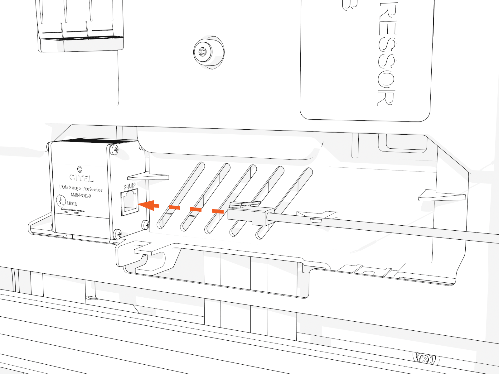
Disconnect the Ethernet cable from the Ethernet surge suppressor.
Take a photo or note to identify which port later.
-
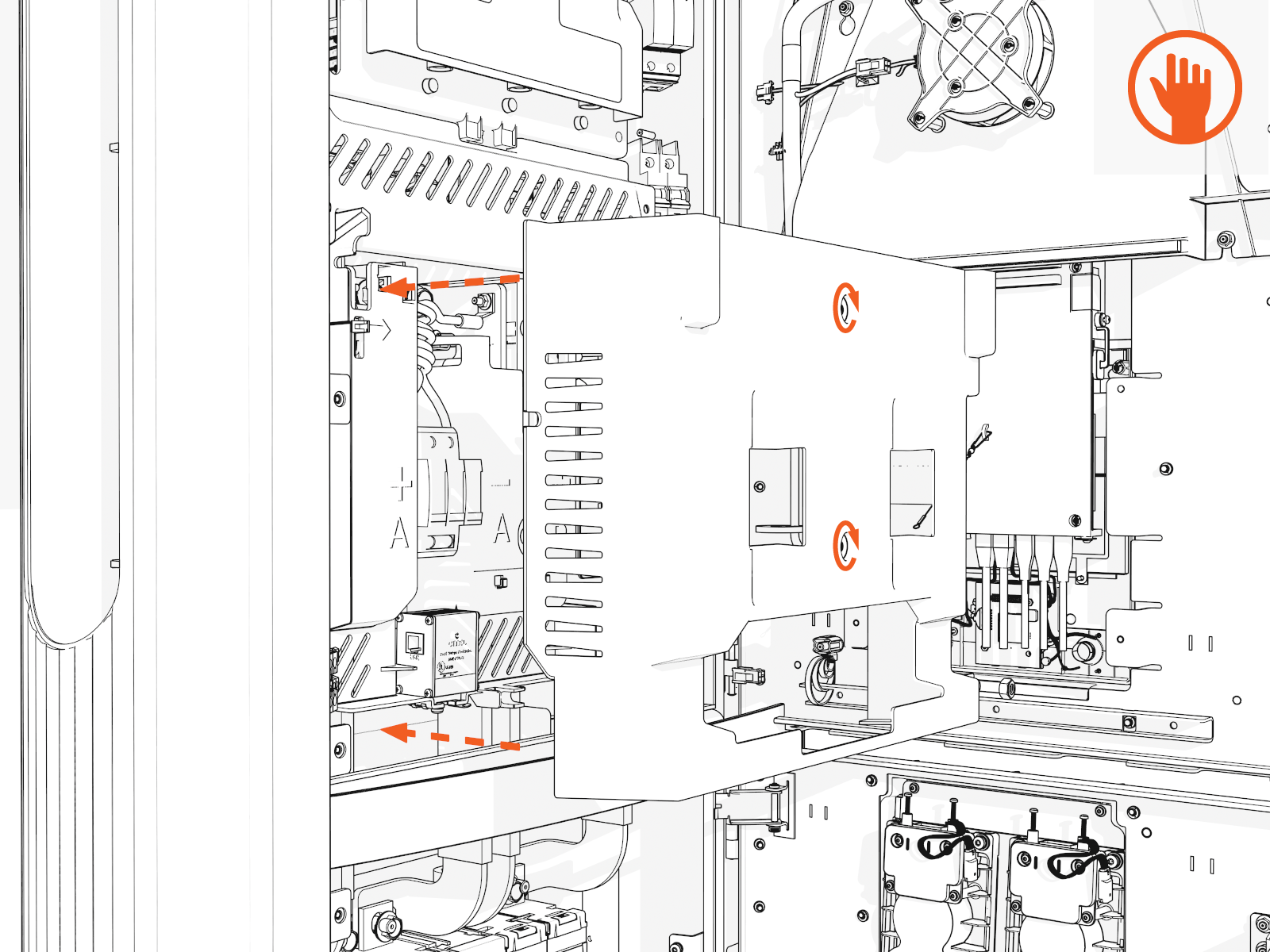
Access the upper bus bars.
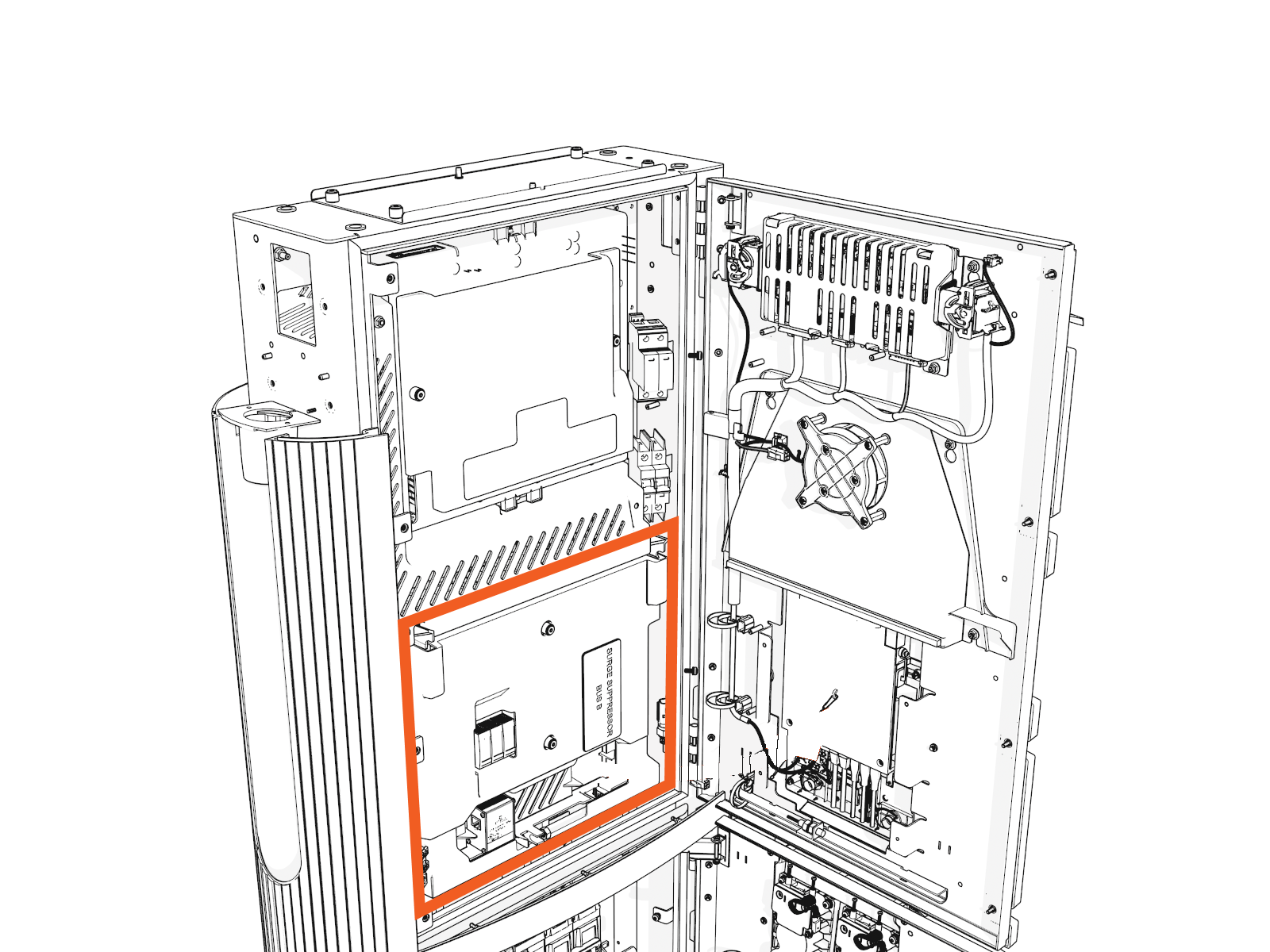
-
On the power plate cover, loosen the captive screws.
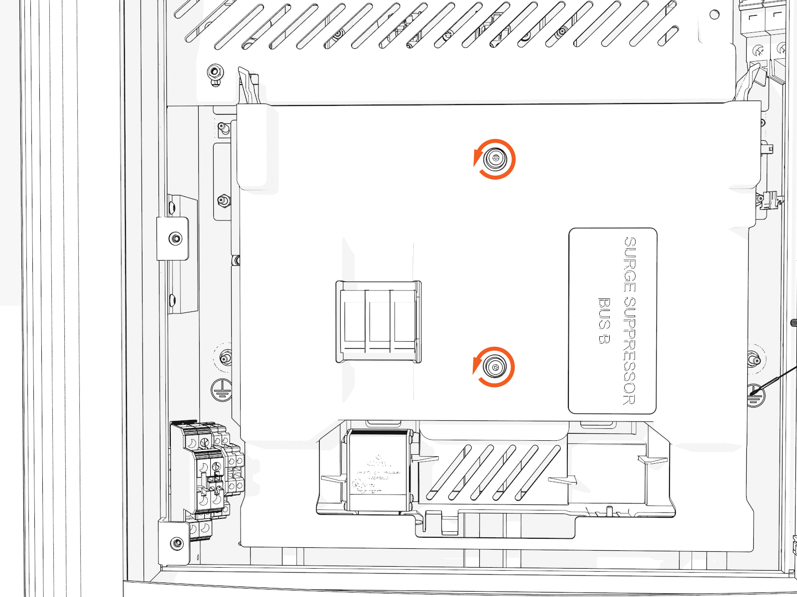
-
Remove the cover.
-
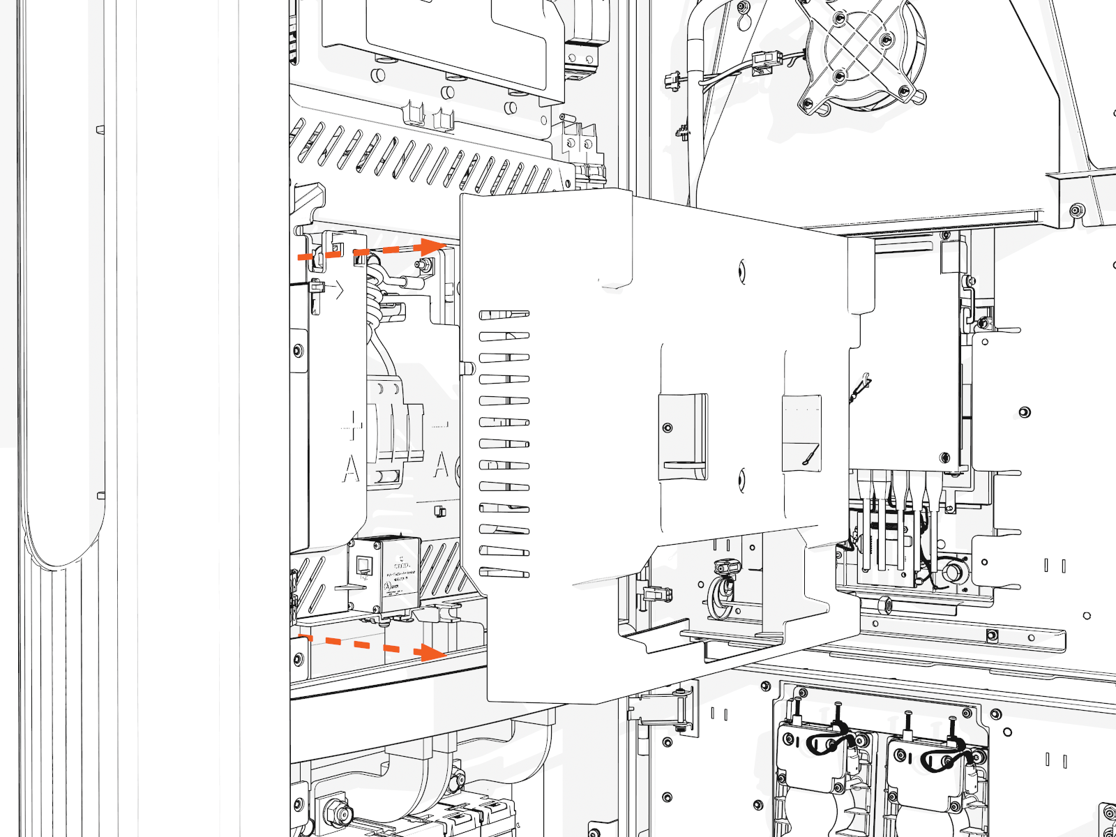
Release the tabs on the upper safety cover.
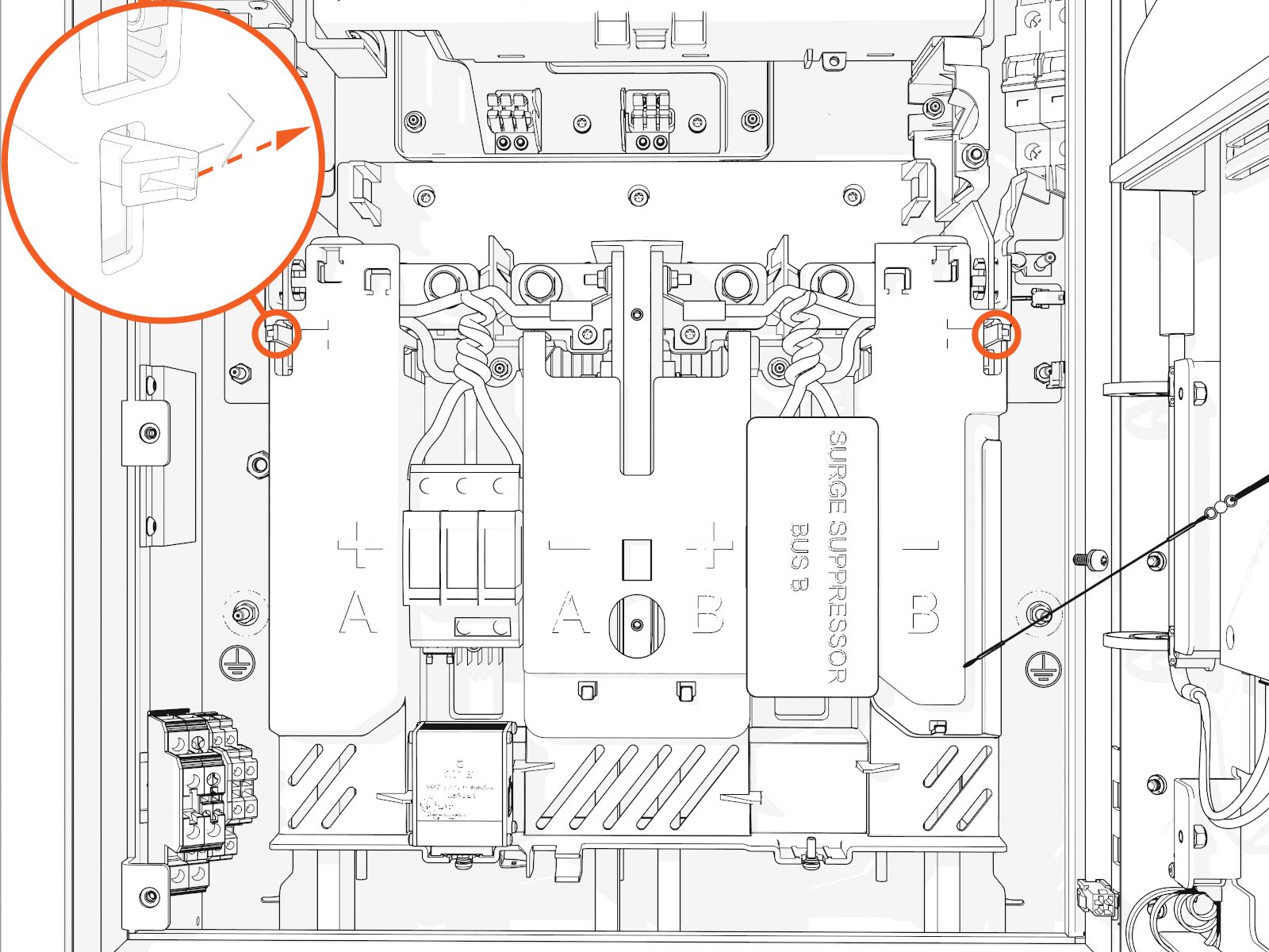
-
Lift up from the bottom until it locks in the open position.
Install DC Conductors and Lugs, and Ground Wire
To install the DC conductors and lugs, and ground wire, complete the following steps:
-
Ensure you have de-energized the applicable circuit and locked out/tagged out the disconnect according to standard practice and local code before proceeding.
-
Use a multimeter to test that power is off.
-
Route all conductors into the correct area within the cabinet.
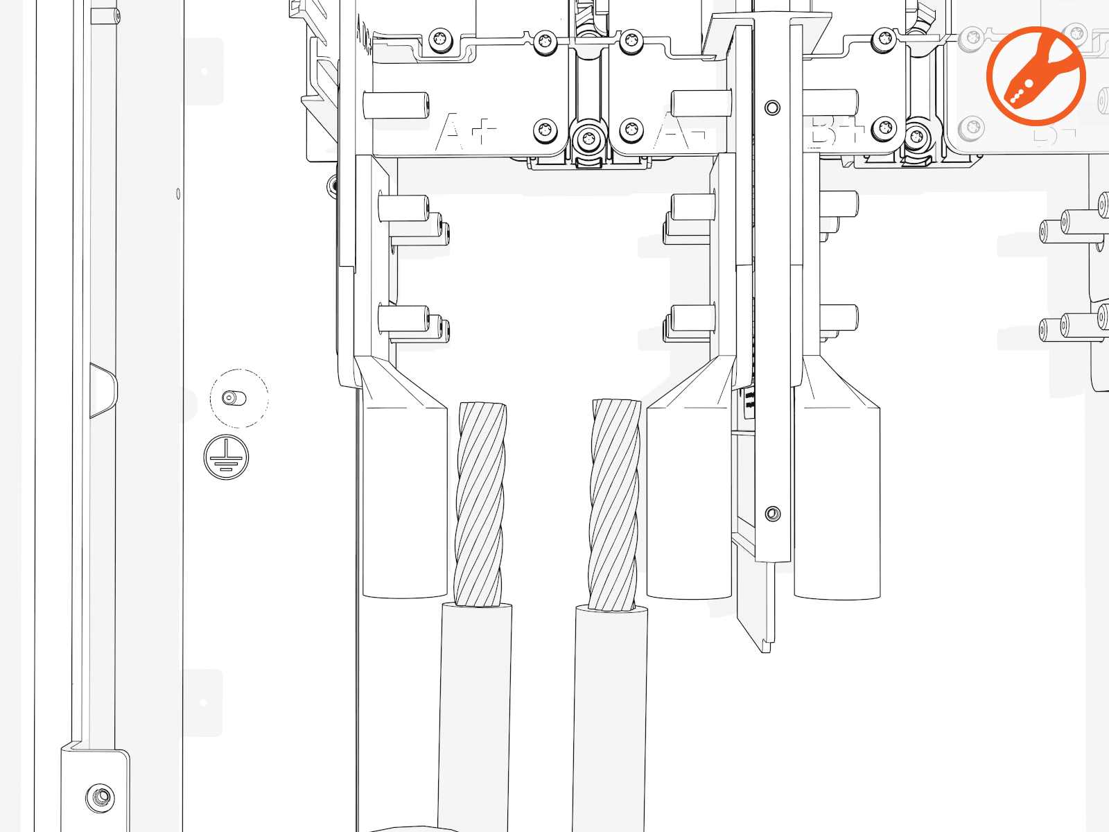
Measure and cut
-
Loosely install lugs only (without the conductors) onto bus bars. Hand-tighten.
Use included bolts, washers, and nuts
-
Measure the length from each conductor to its corresponding lug.
Mark each conductor at the point where you will need to trim it.
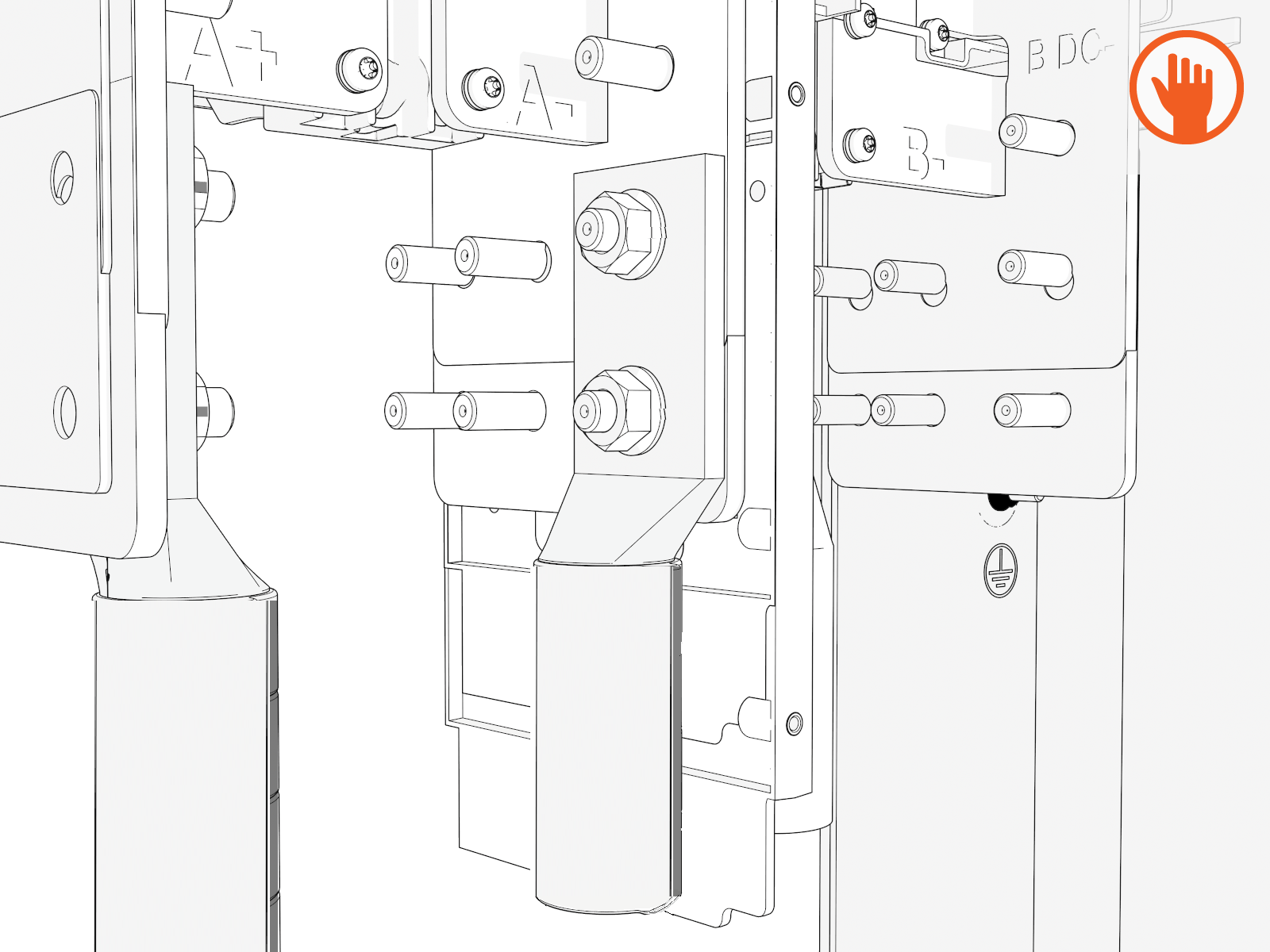
DC bus bars are marked in order from left to right:
Single Input Dual Input A+
A-
A+
A-
B+
B-
-
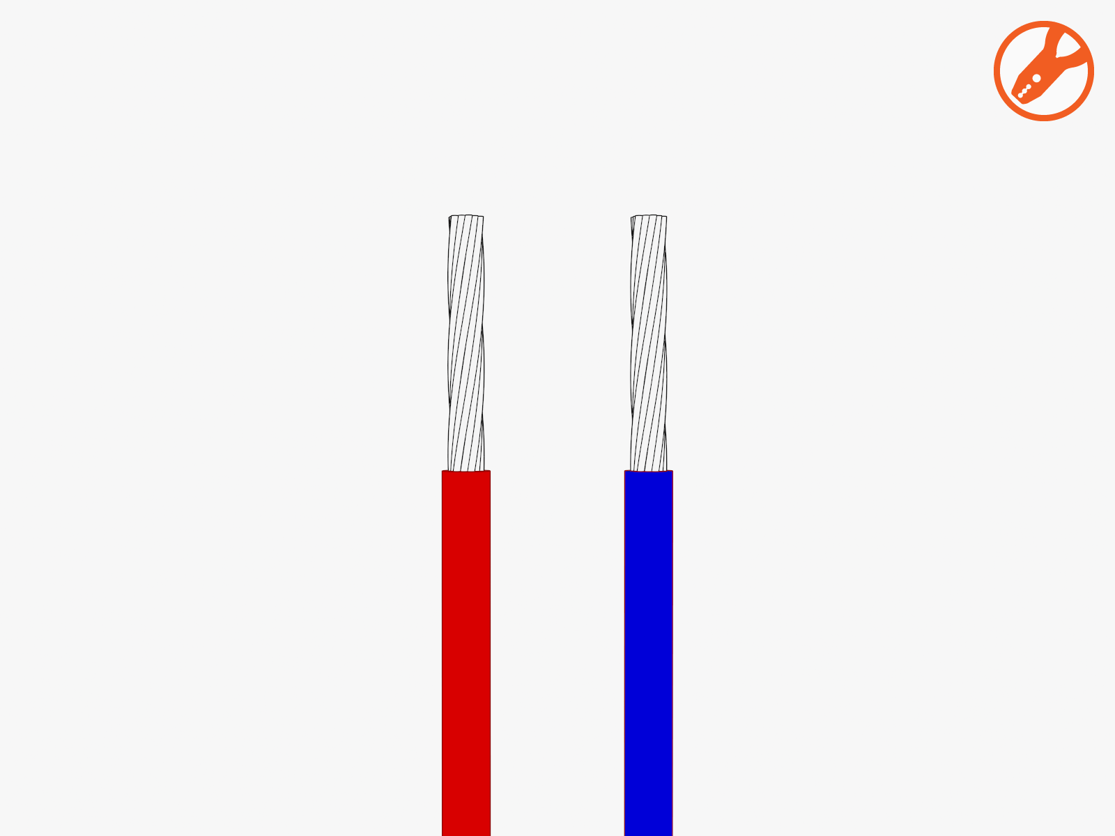
Strip and cut the conductors to the desired length.
Install DC lugs
-
Uninstall the lugs. Crimp a lug onto each conductor.
Use compression lugs with the specifications . Use the lug manufacturer’s tool and die. If required, heatshrink or tape the crimp area to meet local code.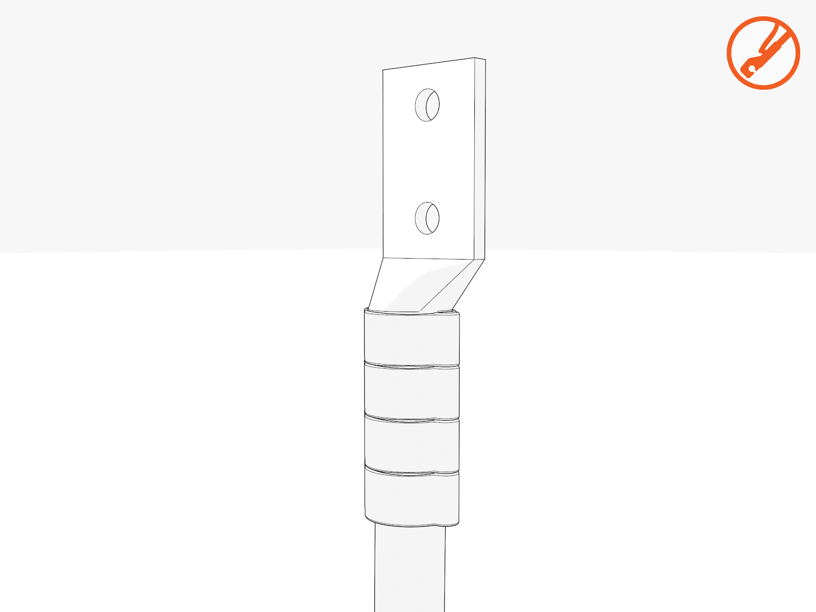
-
Land the DC lugs on the terminals. Torque nuts to 19 Nm (168 in-lb).
Fasteners are pretreated with dielectric grease.If using 500 kcmil conductors, you must use the back set of lugs to avoid interference with the surge suppressor panel.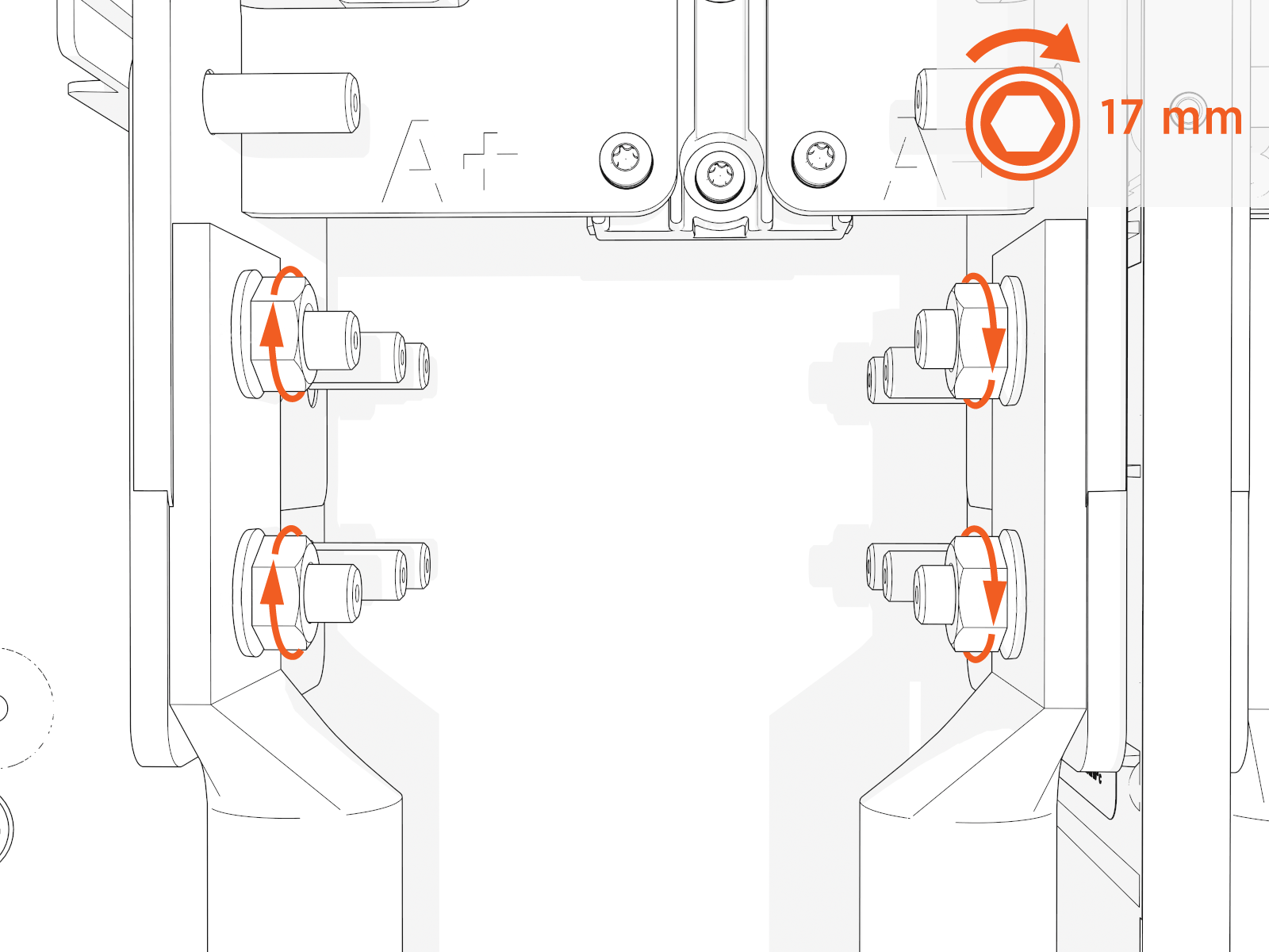
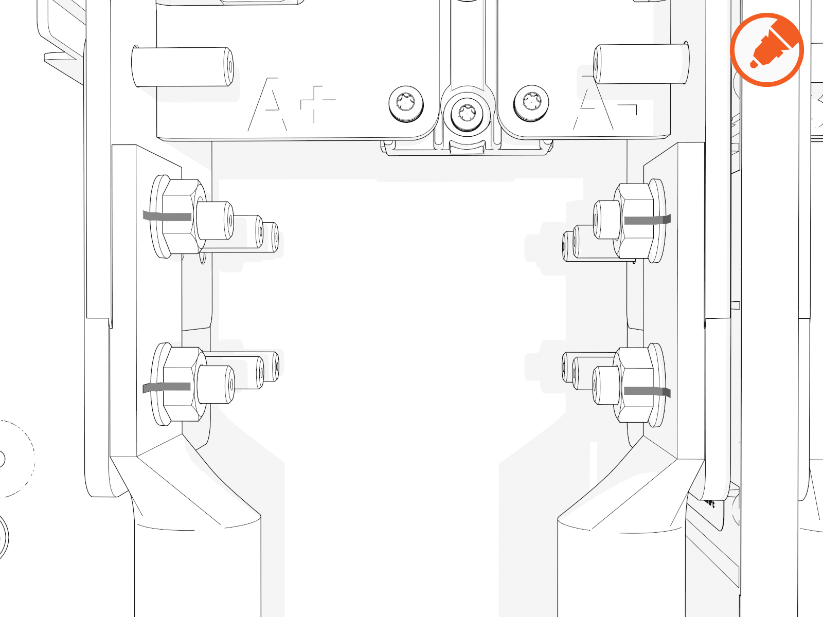
-
Mark all torqued power connections.
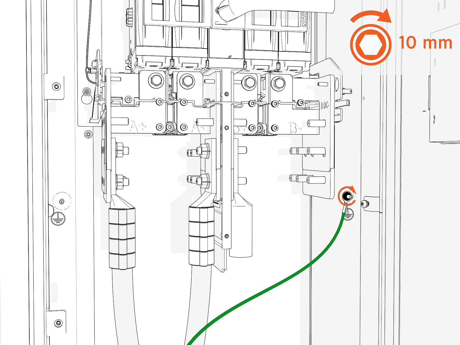
Install DC ground wire
-
Land the ground wire onto a ground stud. Torque to 7 Nm (60 in-lb).
-
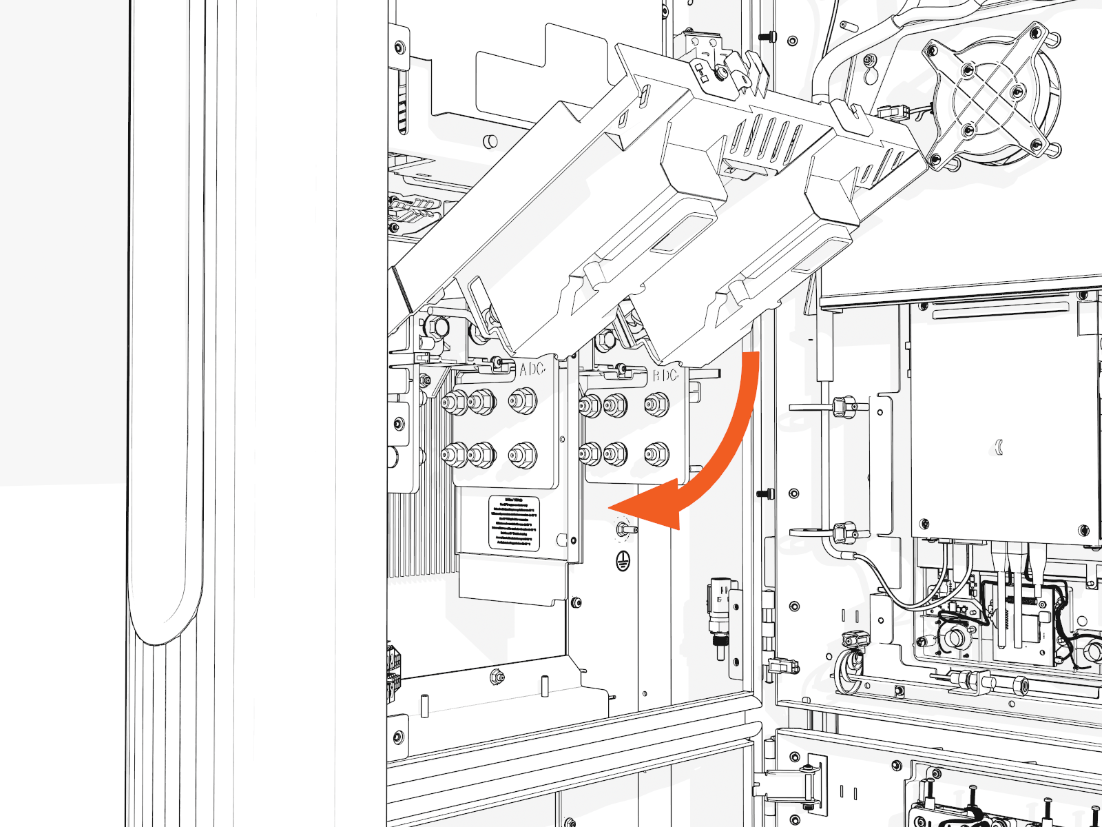
If you are installing the "Overhead" Mounted configuration:
Tilt down the upper safety cover to close.
-
Position the power plate cover. Hand tighten the captive screws.
-
Reconnect Ethernet cable(s) to Ethernet surge suppressor into the same ports as before.
48 V DC Wiring
-
Check the 48 V DC wiring requirements in the site drawings:
48 V DC Wiring 48 V DC Wire Size
Conduit Size
Installation
16 mm2 (6 AWG
 American Wire Gauge)
21 mm (3/4 in)
Install two 48 V DC wires and one Ethernet cable into one conduit.
Use only copper conductor wire rated for 90 °C (194 °F).
-
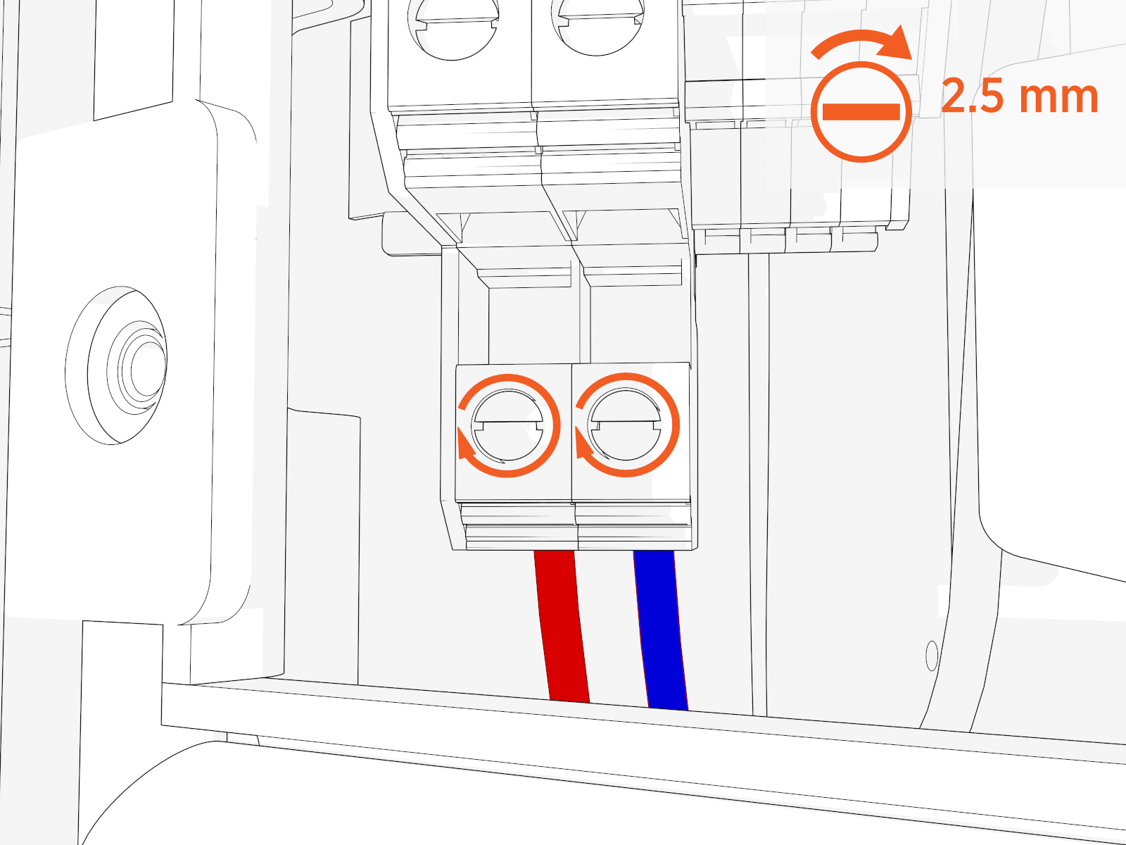
Strip the 48 V DC wires.
-
Loosen each terminal tab (upper cabinet, left side).
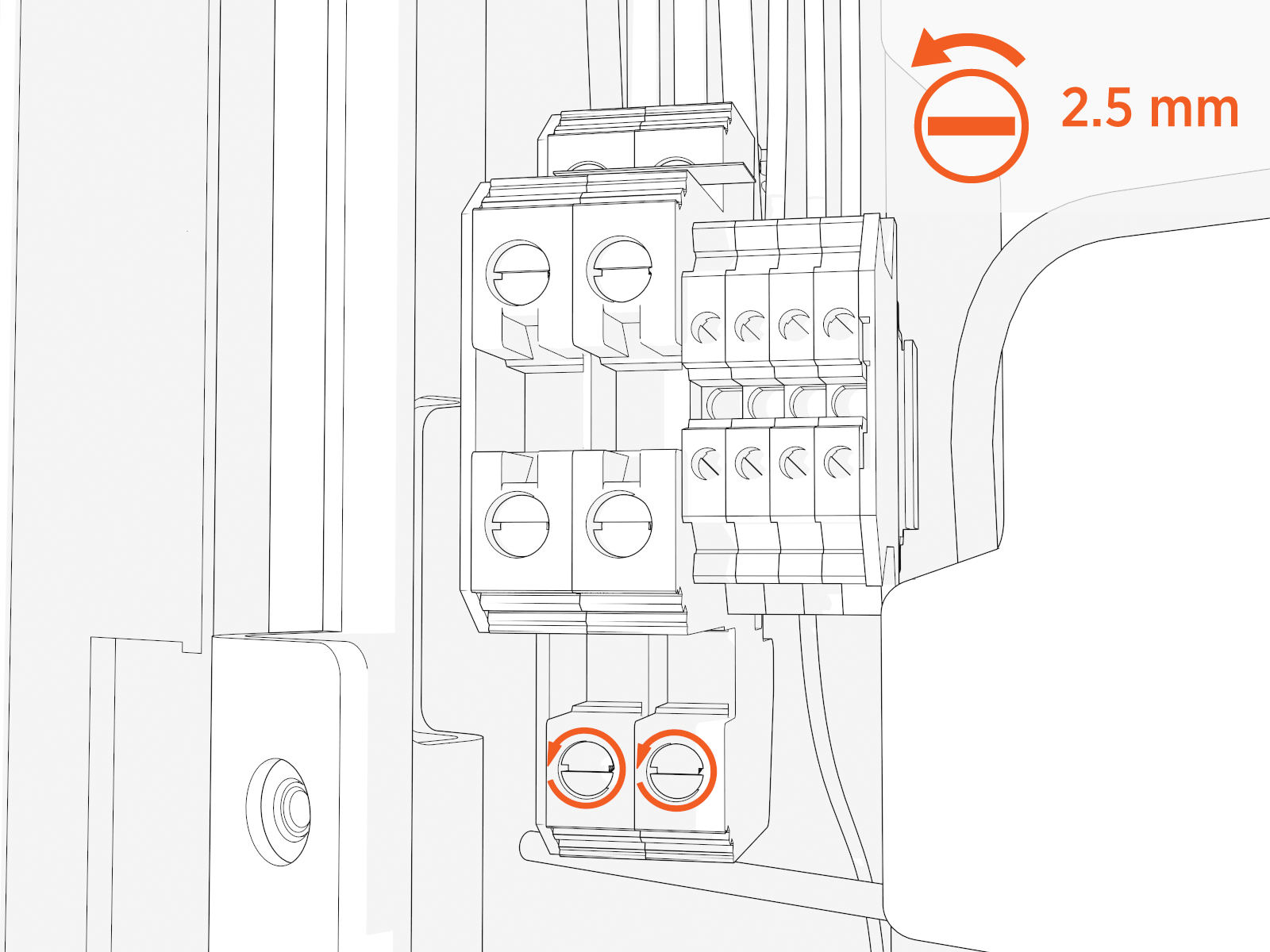
-
Seat the 48 V DC wires. Push-pull to test.
-
To close the pane, lift back of hinge.
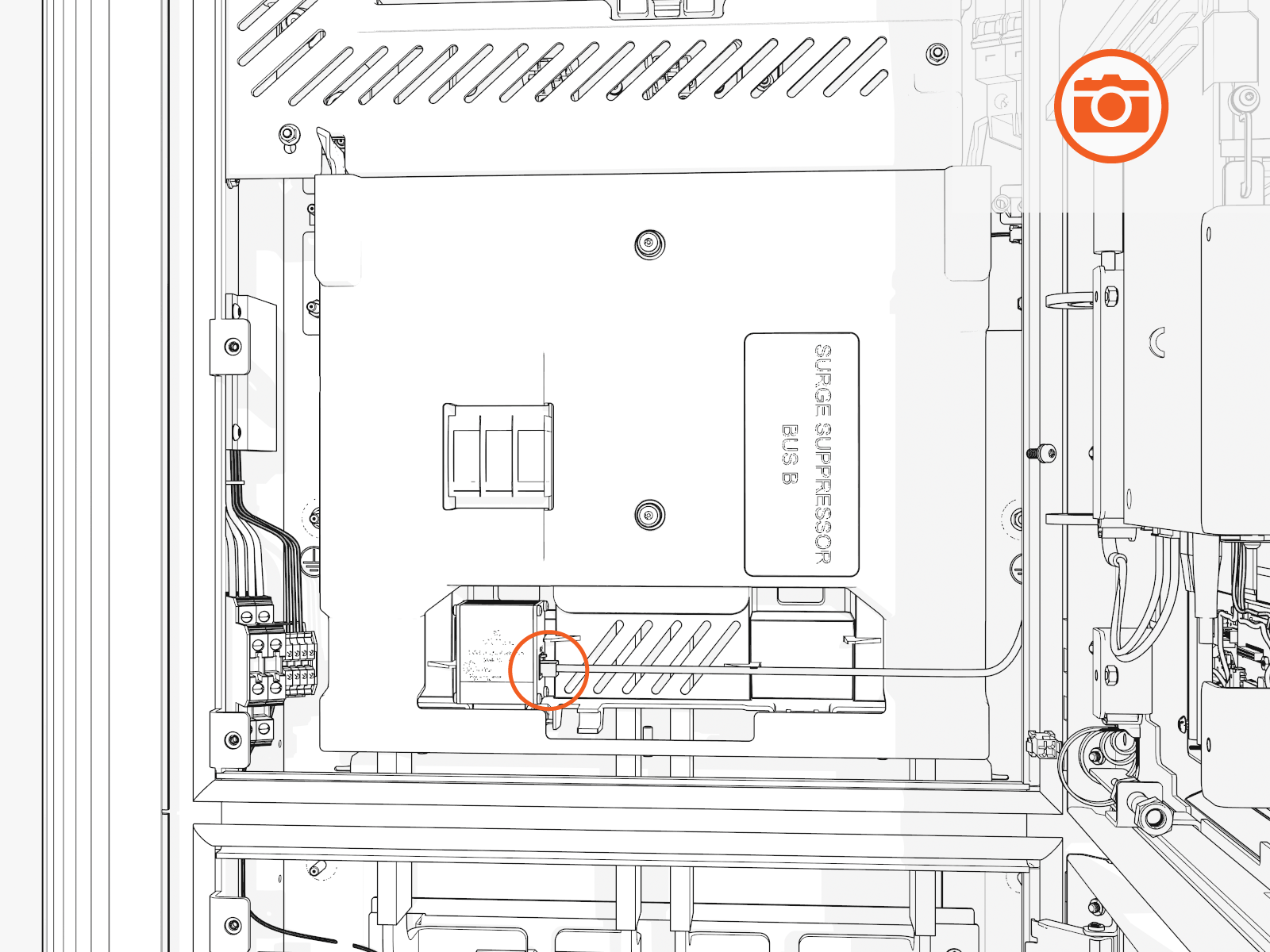
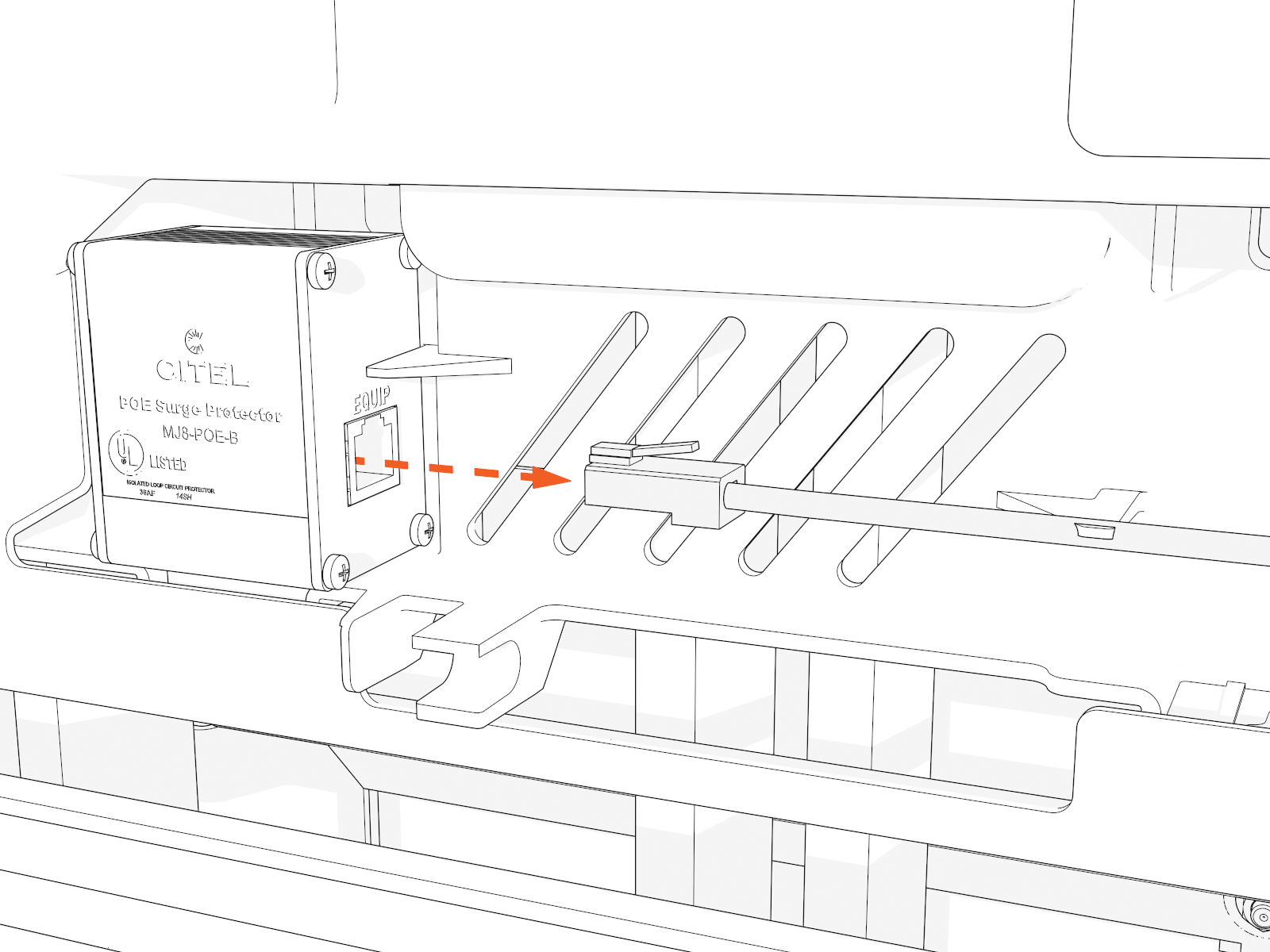
Cat6 STP Ethernet Cable
-
Trim the Cat6 STP
Shielded Twisted Pair Ethernet wires to length and allow for a service loop. Terminate both ends. -
Field crimp a shielded connector onto each Cat6 STP
Shielded Twisted Pair Ethernet wire. Use a straight-through T568B pattern.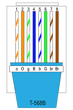
Do not connect the shield wire here at the Power Link 1000 termination.
-
Test each Ethernet wire for functionality.
-
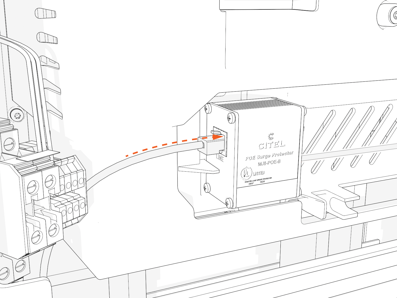
Identify which blue surge suppressors already have cables in the line-out (right) positions. Connect the Ethernet connectors to those surge suppressors at the line-in (left) positions. Push-pull to test.
Install DC Smart Cable
To install DC smart cable or cables, see Install DC Smart Cable.
After installing the cables, return back to this section of the guide and proceed to the next step.
Install Doors and Vinyl Signs
To install doors and vinyl signs, complete the following steps:
Power On 48 V
-
Locate the 48 V DC breaker.

-
Flip up the switch to ON. The indicator light should turn red.

Install Door
-
Disengage wind stops and close the door.
-
Torque screws on the door to 4.5 Nm (40 in-lb).
-
On the right side of the door, insert the bottom of the door bracket. Tilt in the top of the door bracket. Push down into position.
-
Torque screws on the door bracket to 1 Nm (10 in-lb).
Install Vinyl Signs, Trim, and Top Cover

-
Top cover
-
CCOM
Control and Communications Module trim (optional, not shown) -
Lower trim
-
Vinyl sign
-
Bottom cover
-
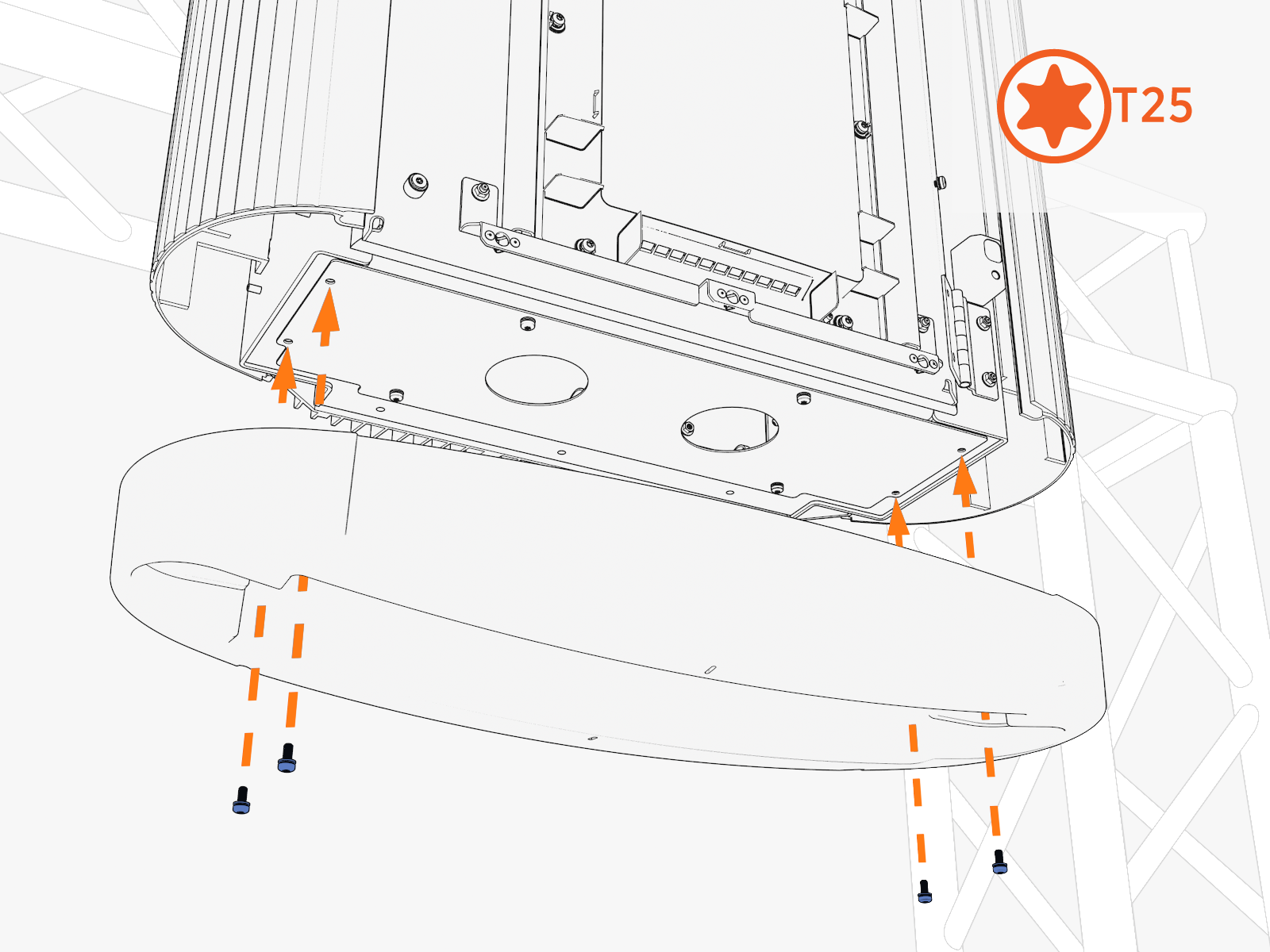
Position the bottom cover.
-
Reinstall screws. Torque to 2.8 Nm (25 in-lb).
-
Push in the lower trim until it engages with the center and side clips.
-
Simultaneously insert both sides of the vinyl sign. Lower the vinyl sign behind the lower trim.
-
Align the screws (x4) (two at front and two at rear) and install the top cap.
Front

Rear

-
Torque the M5 screws (x2) at rear side to 2.8 Nm (25 in-lb) and M4 screws (x2) at front side to 1.7 Nm (15 in-lb) (use T25 security screwdriver).
Continue to Charging Cable Instructions
Install the overhead CMK.
