Install Pedestal-Mount Power Link 1000
When installing a pedestal station with a single cable, you may be provided with a single holster bracket and supplemental side panel blank. It is required to install the single holster bracket to activate and commission the station. For more information, refer to the Holster and Holster Bracket or Side Panels (Pedestal Mounted) chapters in the Power Link 1000 Service Guide.
If the site has height constraints for installation, contact ChargePoint to get instructions and clearances that you will need for the modified process. Alternatively, you may use a forklift bracket kit, or a crane with lifting shackles and a spreader bar (constraints may differ among sites).
Disconnect Power
To disconnect power, complete the following steps:
- Before any procedure, disconnect the power.
- Follow local code and site lockout/tagout procedure to de-energize the station.
- Wait for energy to dissipate (approximately five minutes).
- Keep power off until all covers and panels are reinstalled and the work is complete.
-
Disconnect power at the site electrical panel.
Follow standard practice and local code to de-energize the applicable circuit and lock out/tag out the disconnect before proceeding.
-
Use a multimeter to test that the unit is de-energized.
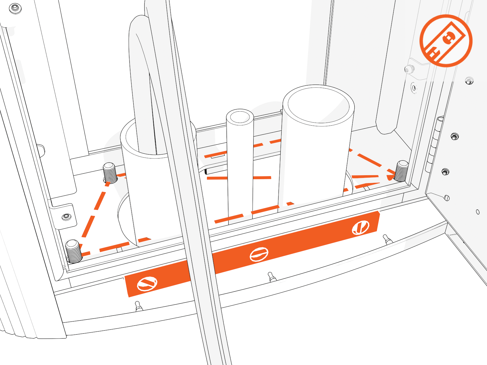
Prepare Power Link 1000 Pad
To prepare the Power Link 1000 pad, complete the following steps:
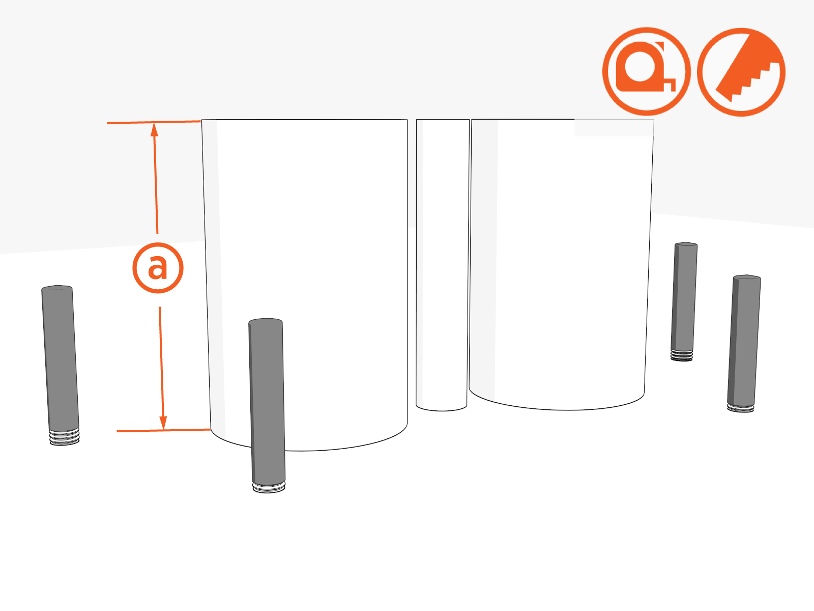
-
Ensure all stub-ups are (a) 102–160 mm (4–6.3 in) high.
If armored cable is used, strip the outer jacket to the same height.
-
Remove plastic caps.
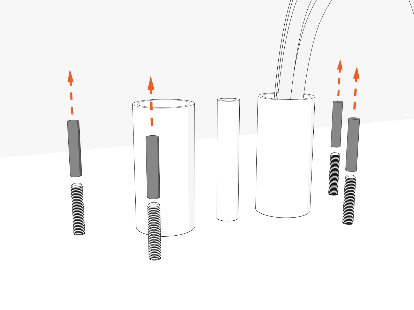
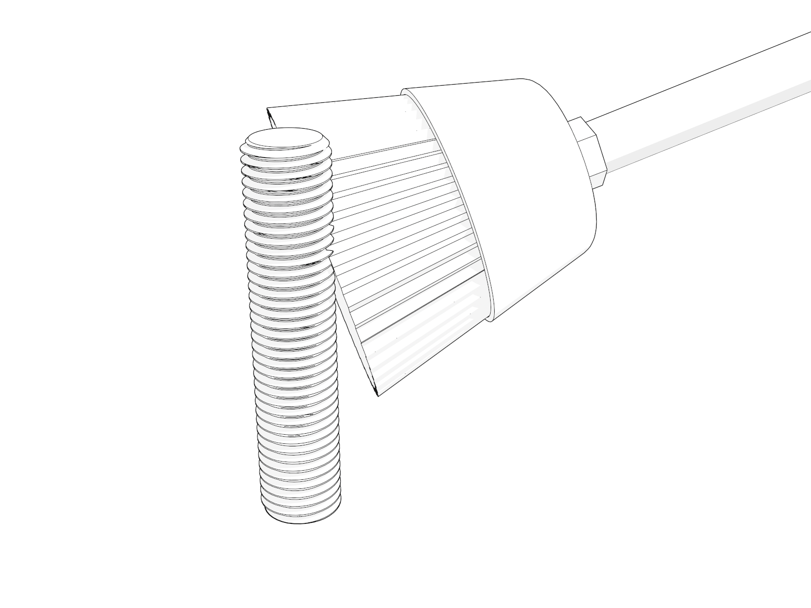
-
Use a wire brush to clean bolt threads.
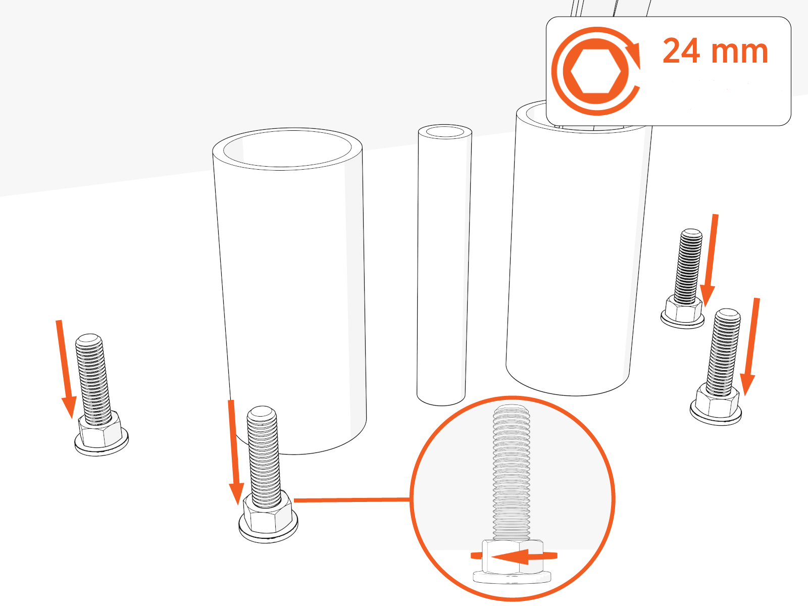
-
Install one concrete clamp washer and nut onto each of the four anchor bolts. Torque to 54 Nm (40 ft-lb).
On epoxied surfaces, do not exceed the epoxy torque rating.
-
Install "leveling" nuts and washers onto the bolts by hand. Maintain a space of (a) ~6.4 mm (1/4 in) between each leveling nut and bottom nut.
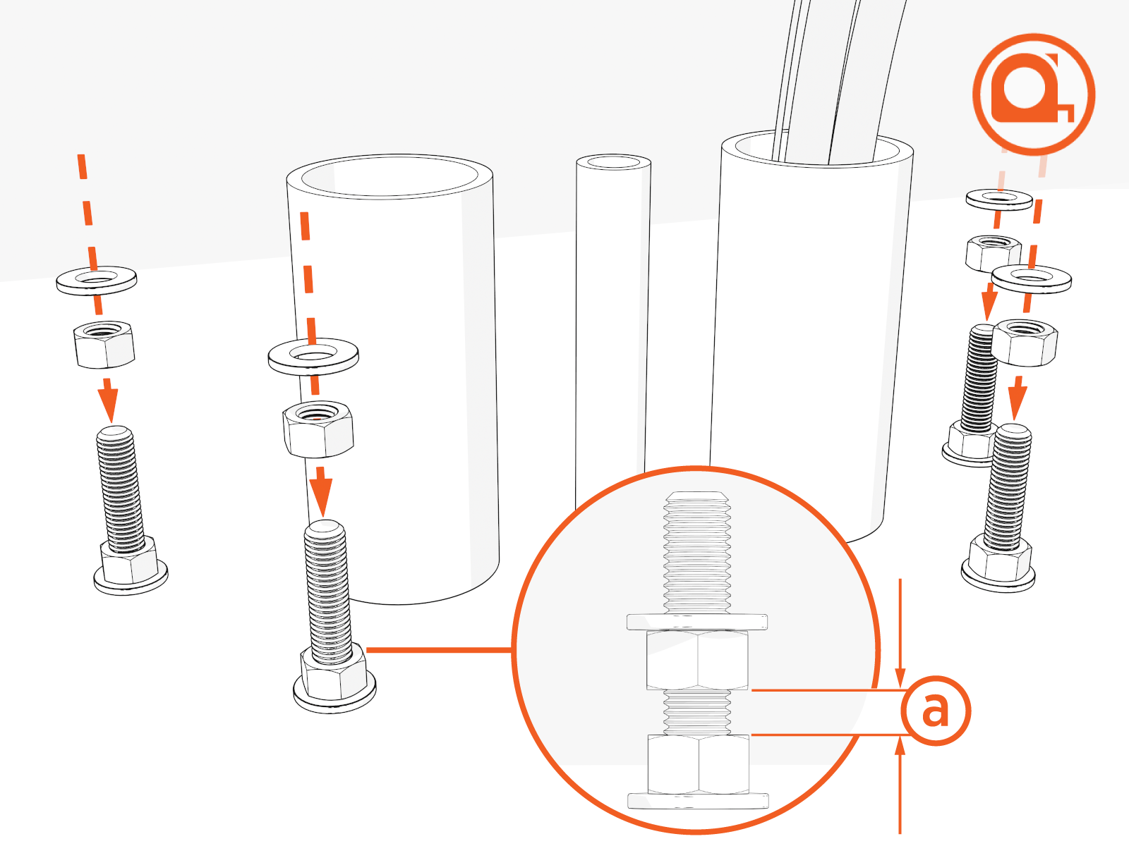
-
Check that leveling nuts are level with each other.
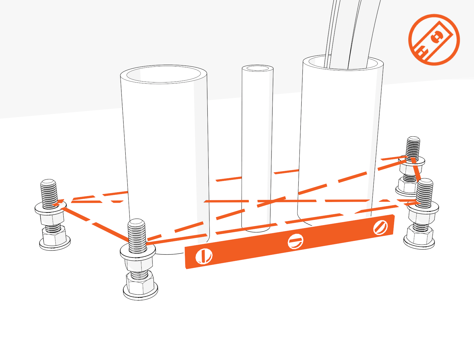
-
Pull service wiring through the conduit (see the Express Plus Site Design Guide). Retain 1524 mm (60 in) of service loop for each cable.
Do not use conduits with bell ends. They may interfere with tolerances inside the enclosure.
Mount and Secure Power Link 1000
To mount and secure the Power Link 1000, complete the following set of steps:
Unpack
-
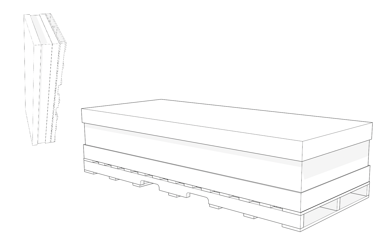
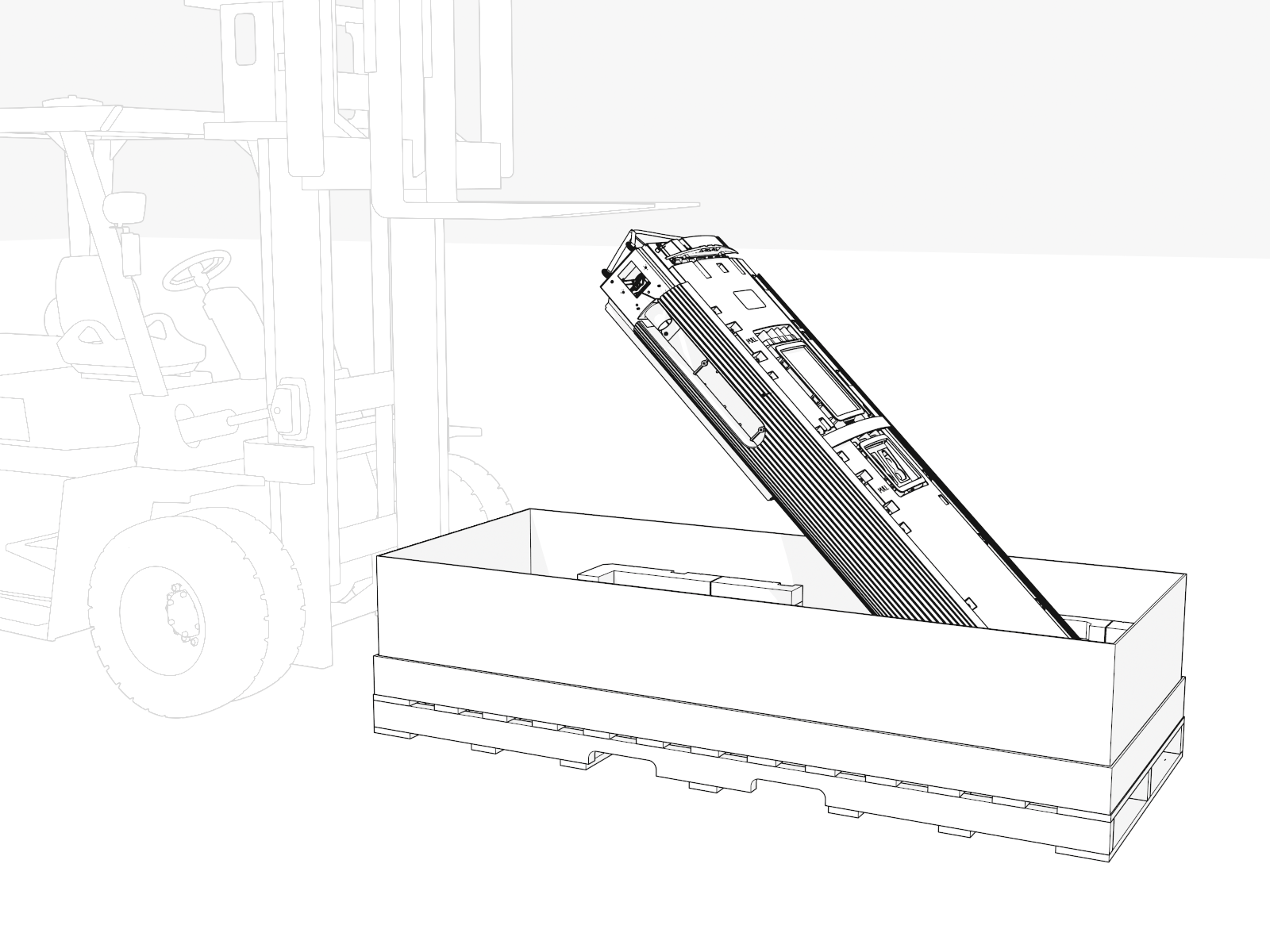
Transport the crate upright to the installation site and then lay it down flat.

The crate is heavy and can cause injury or death if dropped. Do not stand or walk beneath the crate while it is being lifted. Take precautions against the crate tipping or sliding.
-
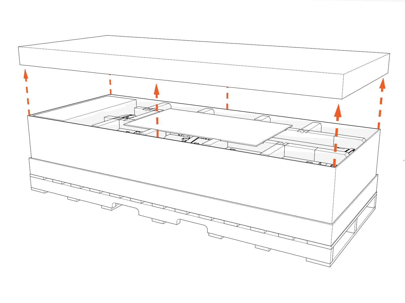
Lift off the crate cover.
-
Set aside the separate packages that are inside the crate.
These packages contain vinyl signs, trims, and top cover (helmet) to be installed later.
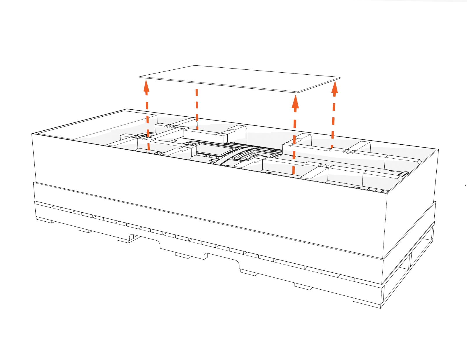
-
Remove the top foam inserts.
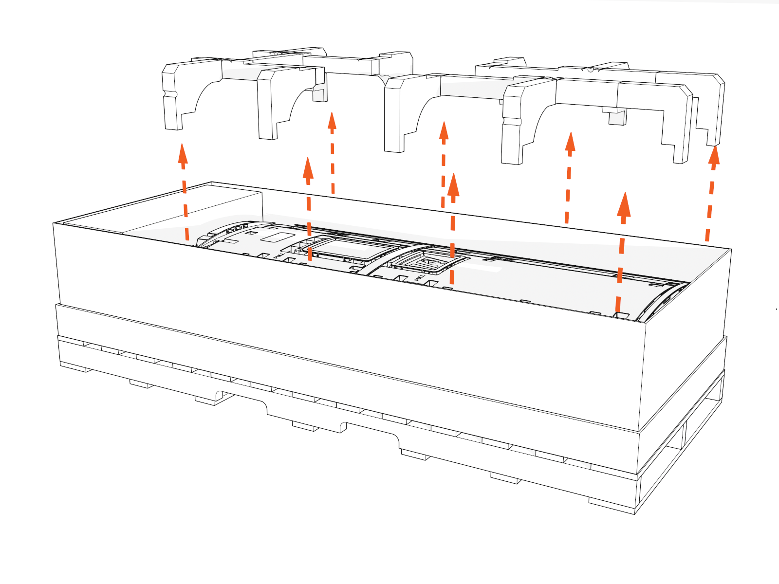
Access Base of Cabinet
To access the base of the cabinet, complete the following steps:
Keep components in a cool area out of direct sunlight until you reinstall them.
-
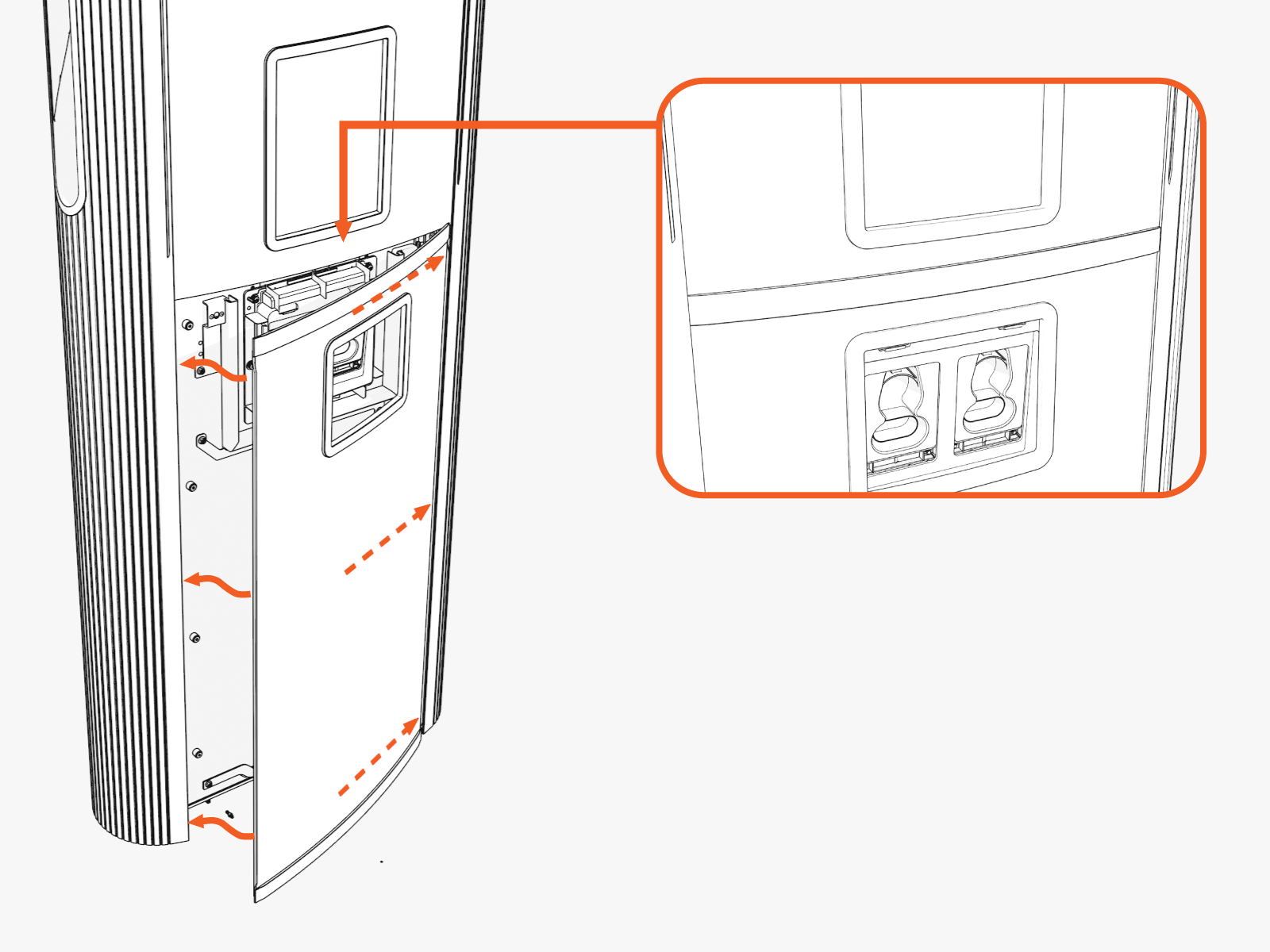
Loosen screws from the lower door bracket (only if covers are B. Install Vinyl Signs, Trims, and Top Cover).
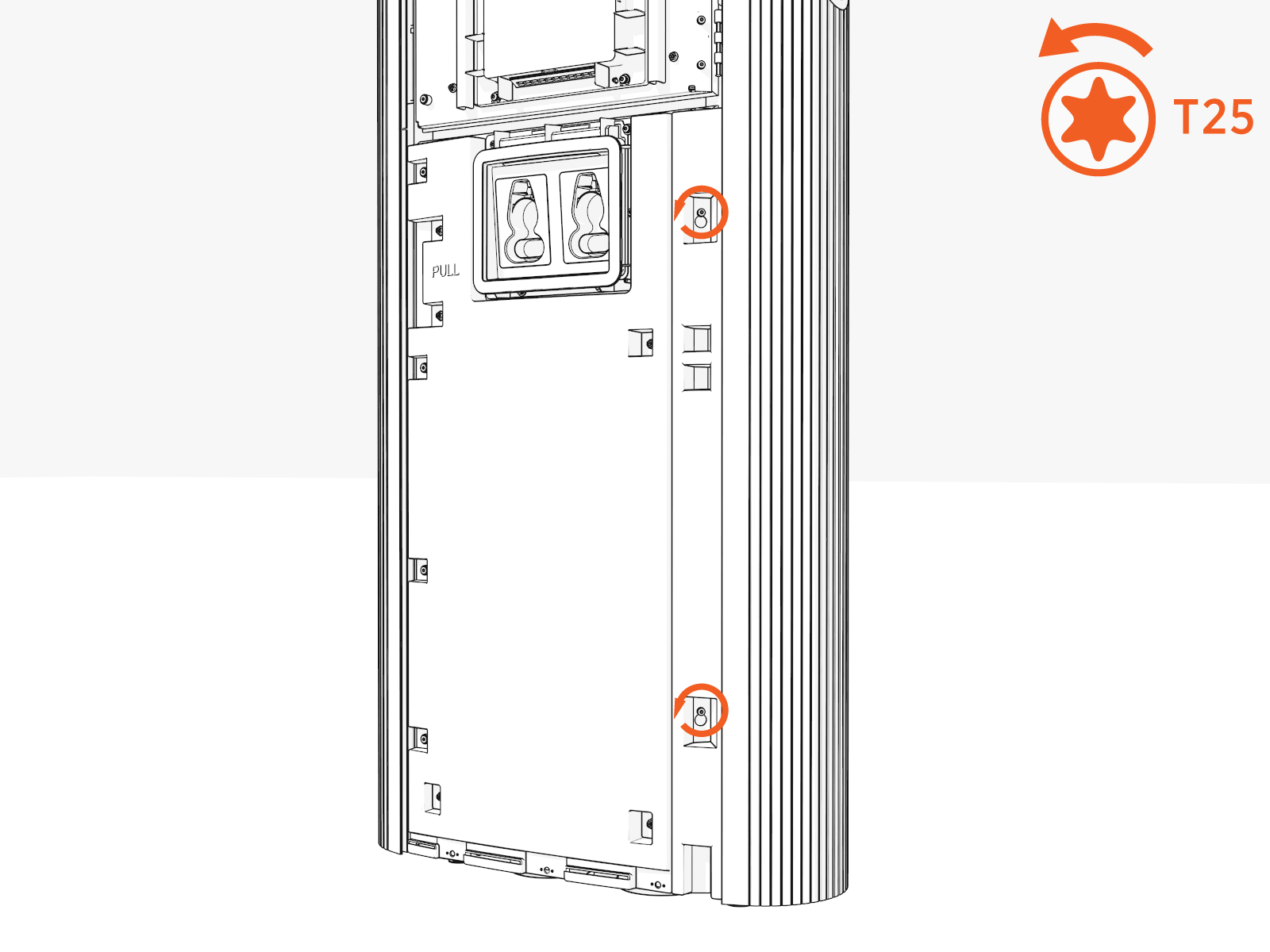
-
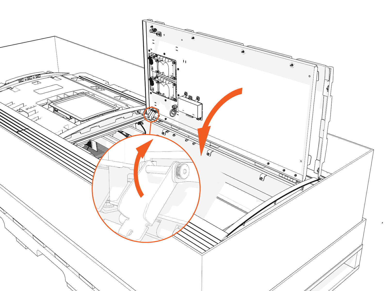
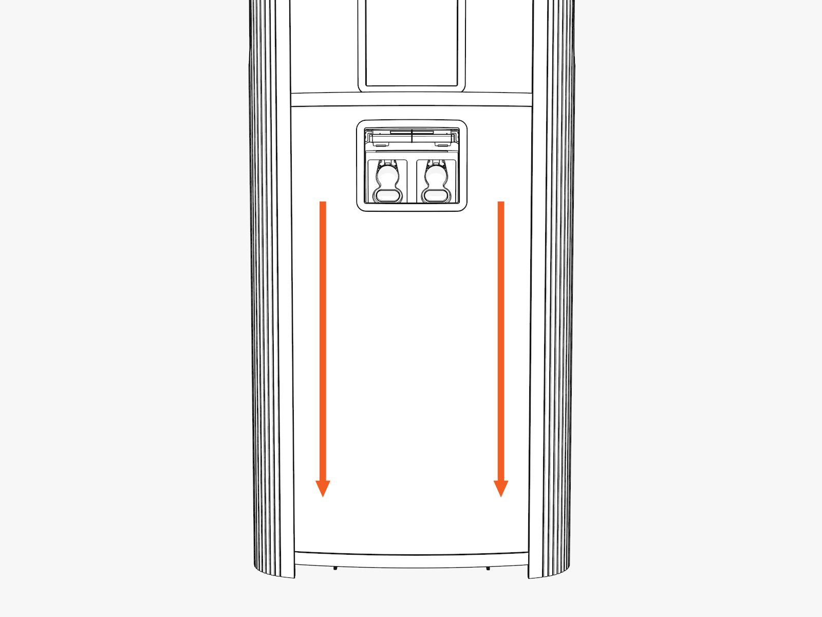
Hold the middle of the door bracket. Lift and tilt out.
-
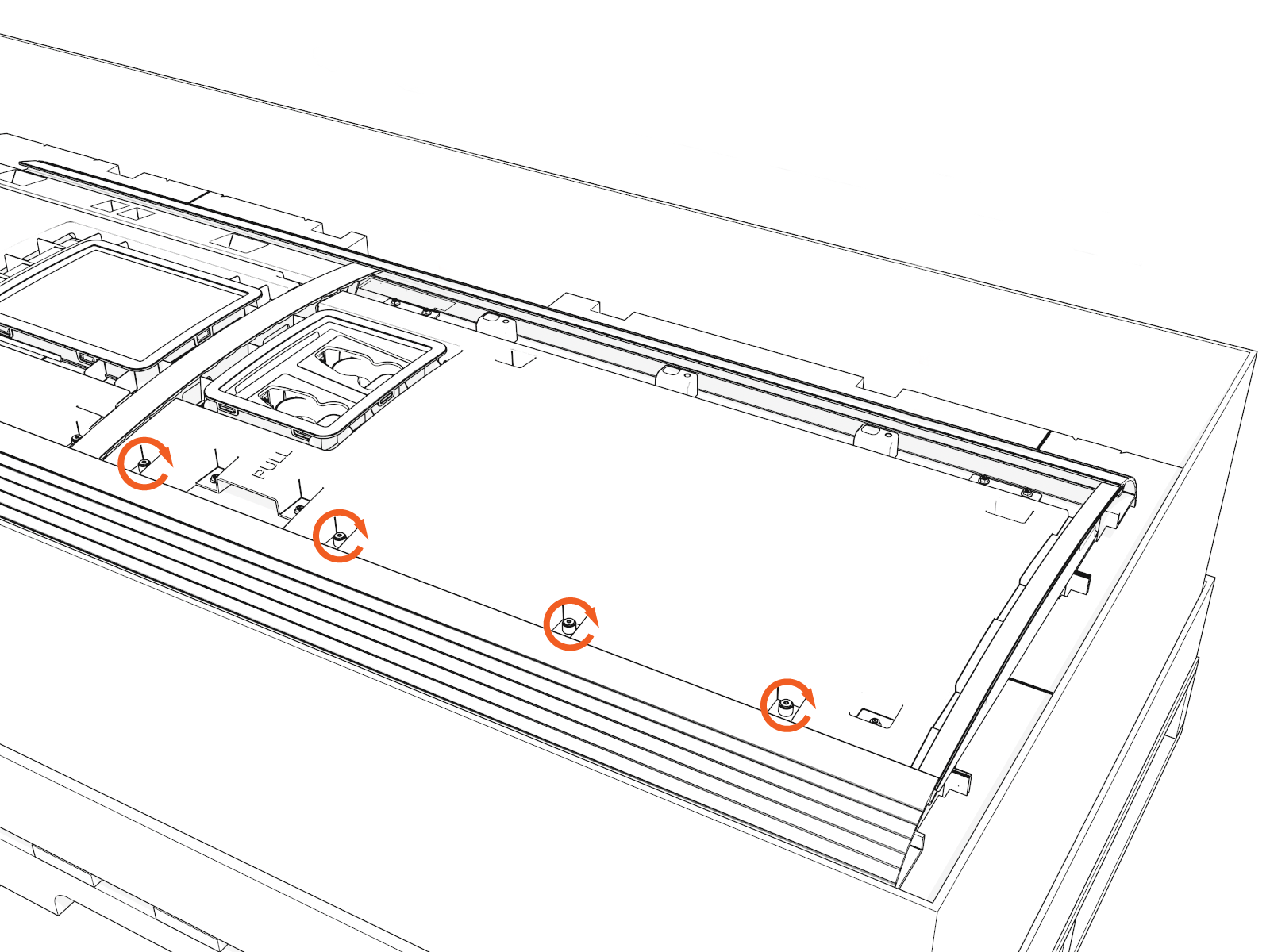
Uninstall screws along the left side to open the door.
-
Rotate the orange wind stops into the door gap.
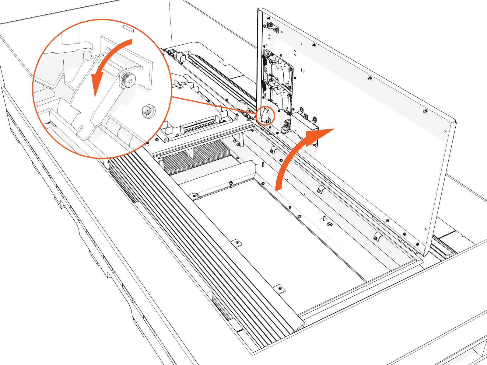
-
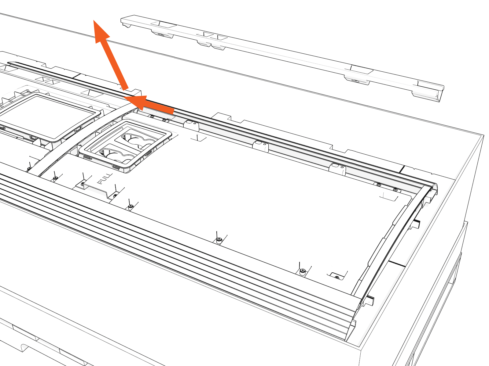
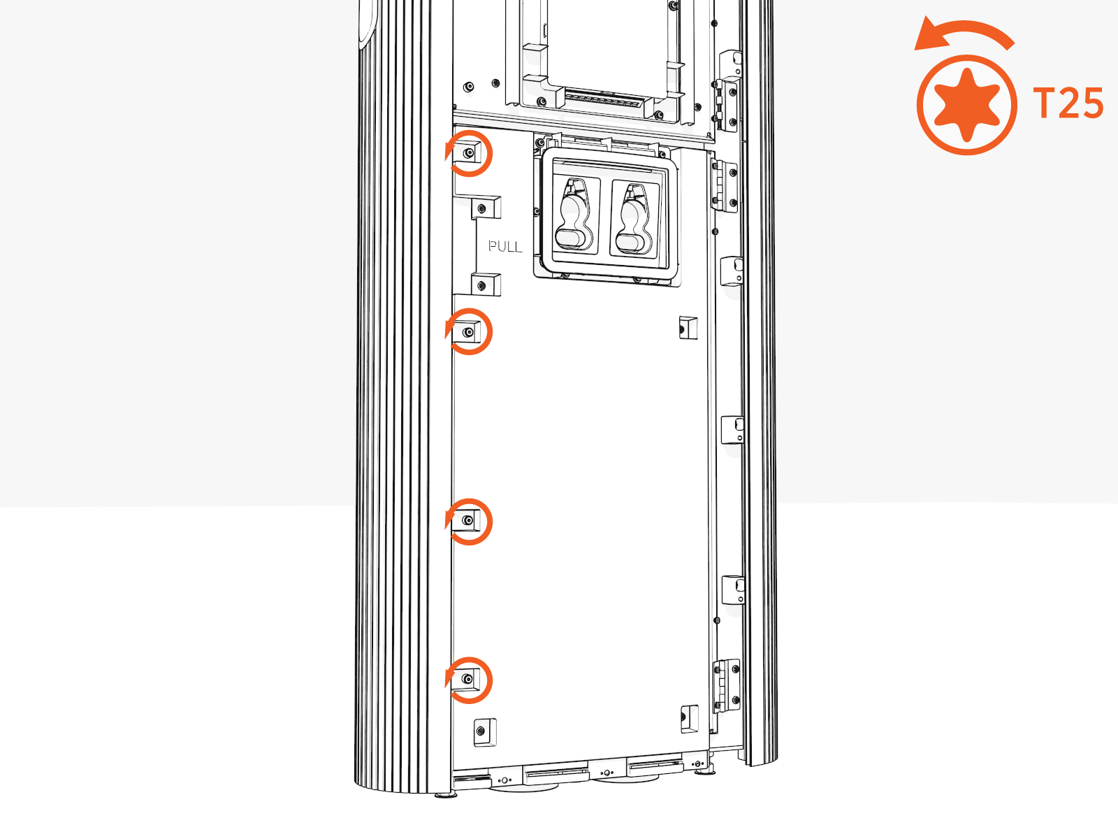
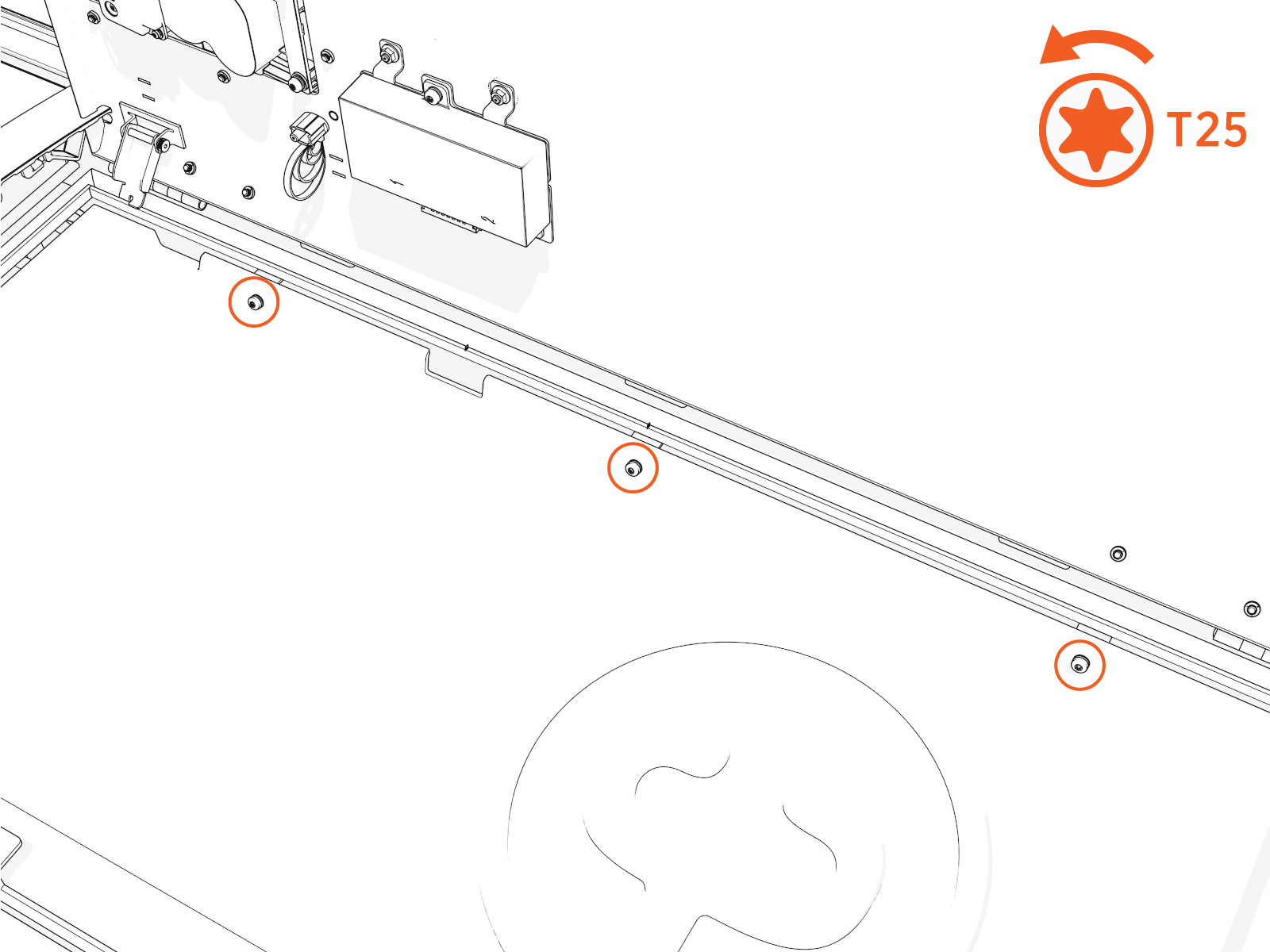
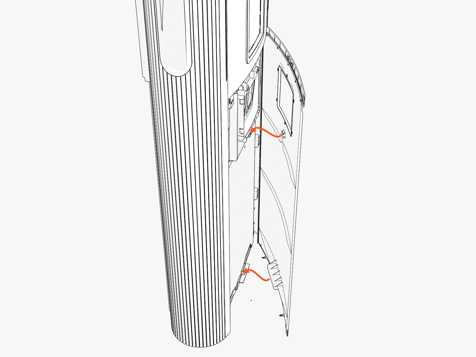
Inside the lower cabinet, uninstall the lower safety panel (if present) and gland plate.
Loosen screws on the right side. Tilt out and slide the panel out of the slots.
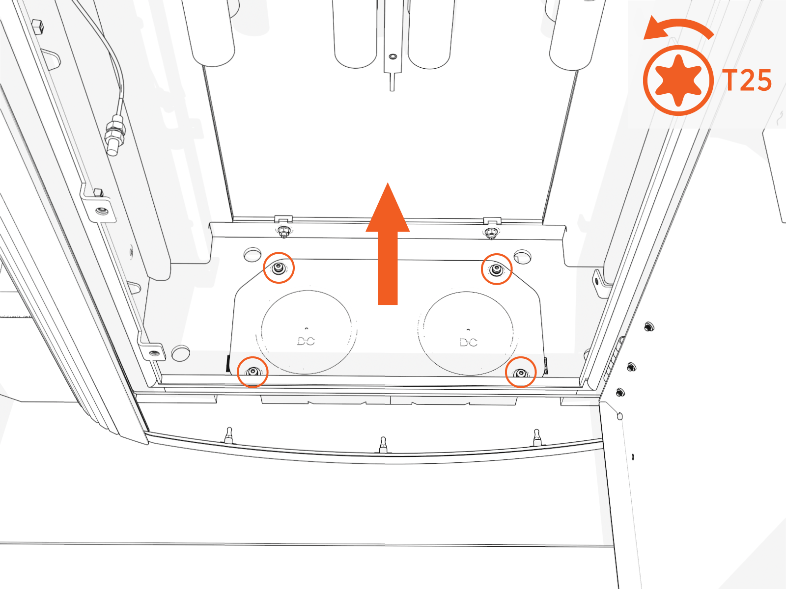
-
Uninstall screws and lift out the gland plate.
-
Temporarily reinstall the lower door.
The upper door should remain closed until a much later step.
-
Disengage the wind stops. Shut the door.
-
Tighten screws by hand.
-
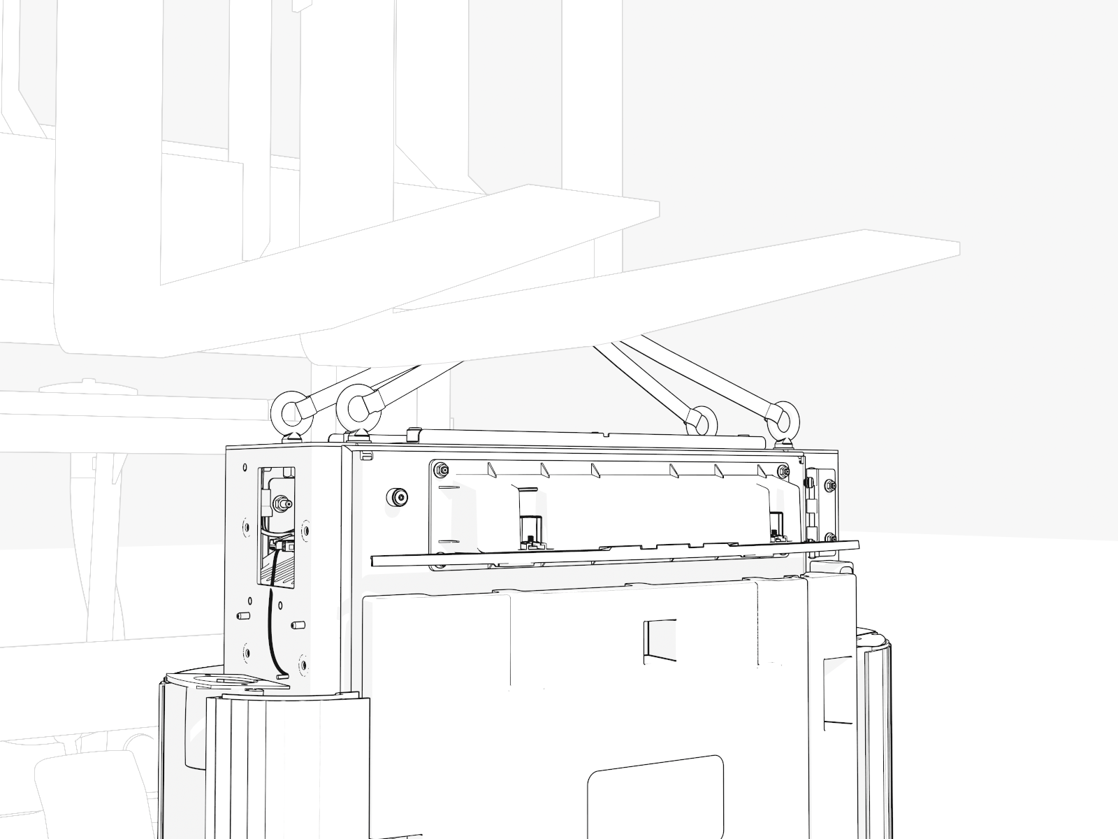
Position the Power Link 1000
To position the Power Link 1000, complete the following steps:
-
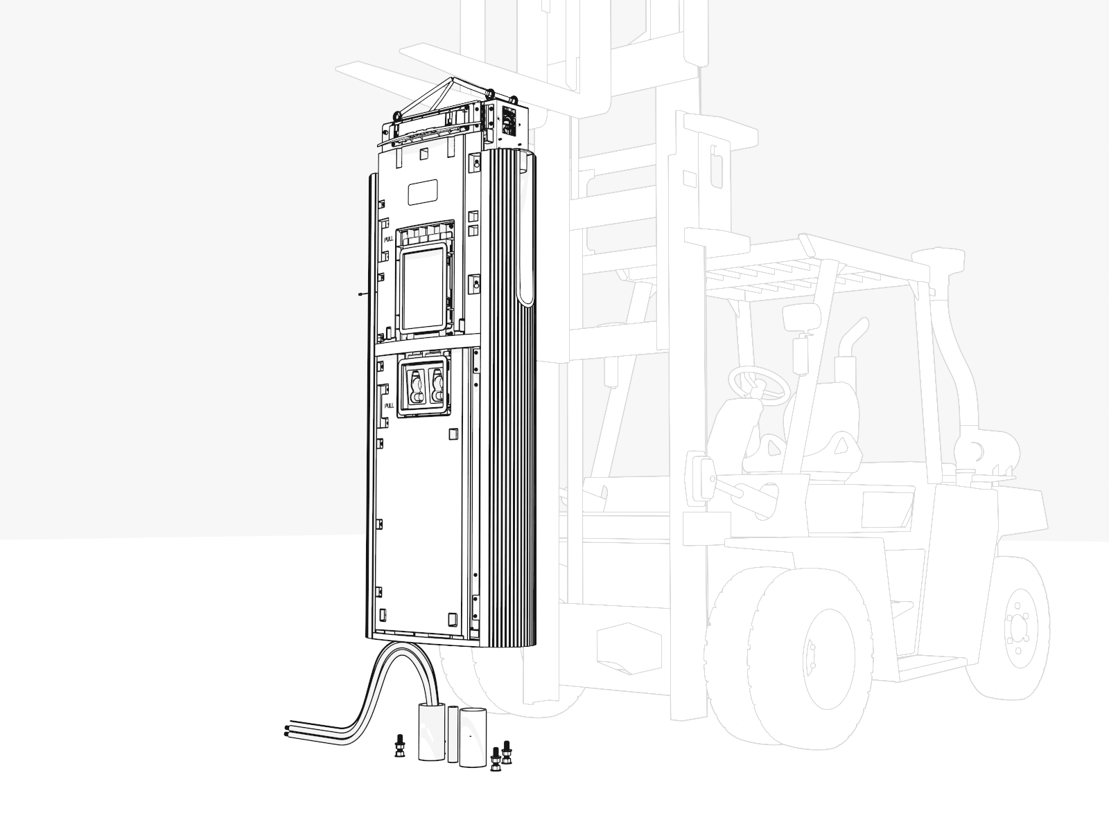
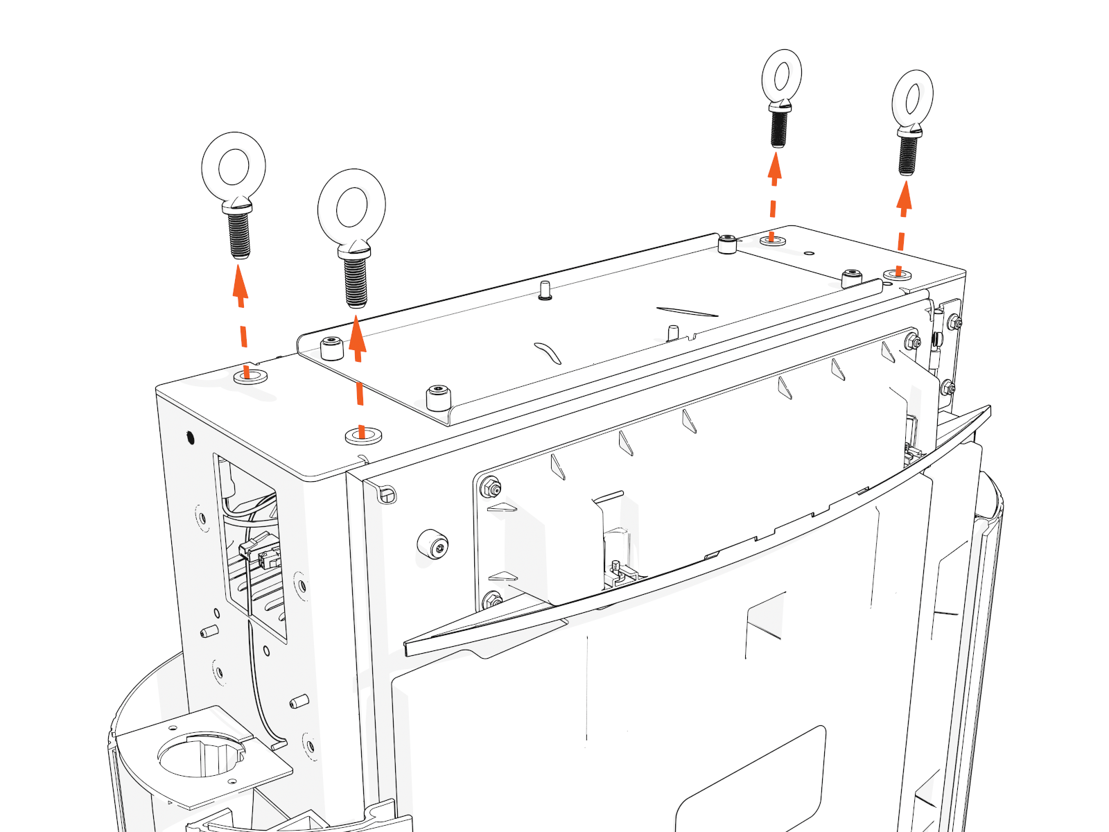
At the top of the Power Link 1000, locate four preinstalled eye bolts and lifting straps.
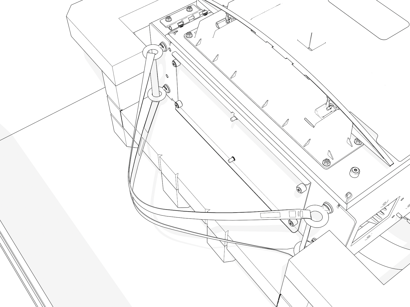
-
Thread the lifting straps through the eye bolts.
-
Move and suspend the Power Link 1000 above the concrete pad. Keep it elevated.
-
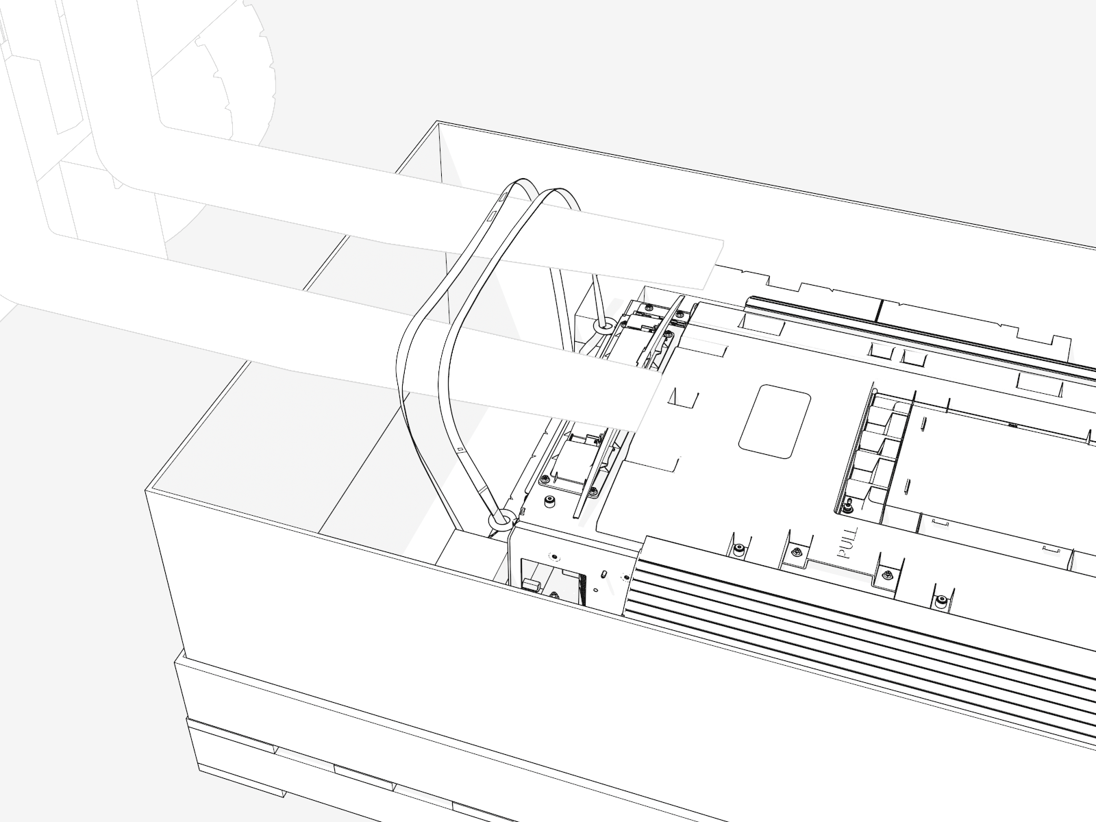
Loosen screws to open the lower door again. Engage the wind stops.
-
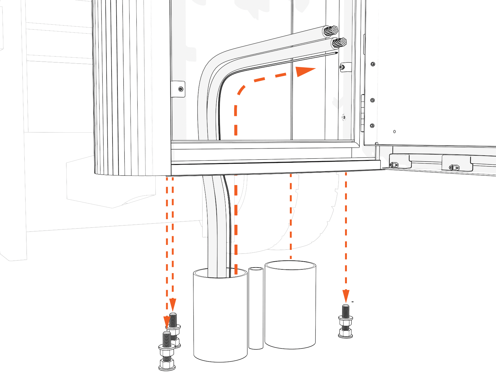
Route wiring through the bottom.
-
Align the holes with the anchor bolts.
-
Slowly move the Power Link 1000 down onto the anchor bolts. Provide slack to the lift straps, but keep them attached.
Continue to pull wiring through bottom.
-
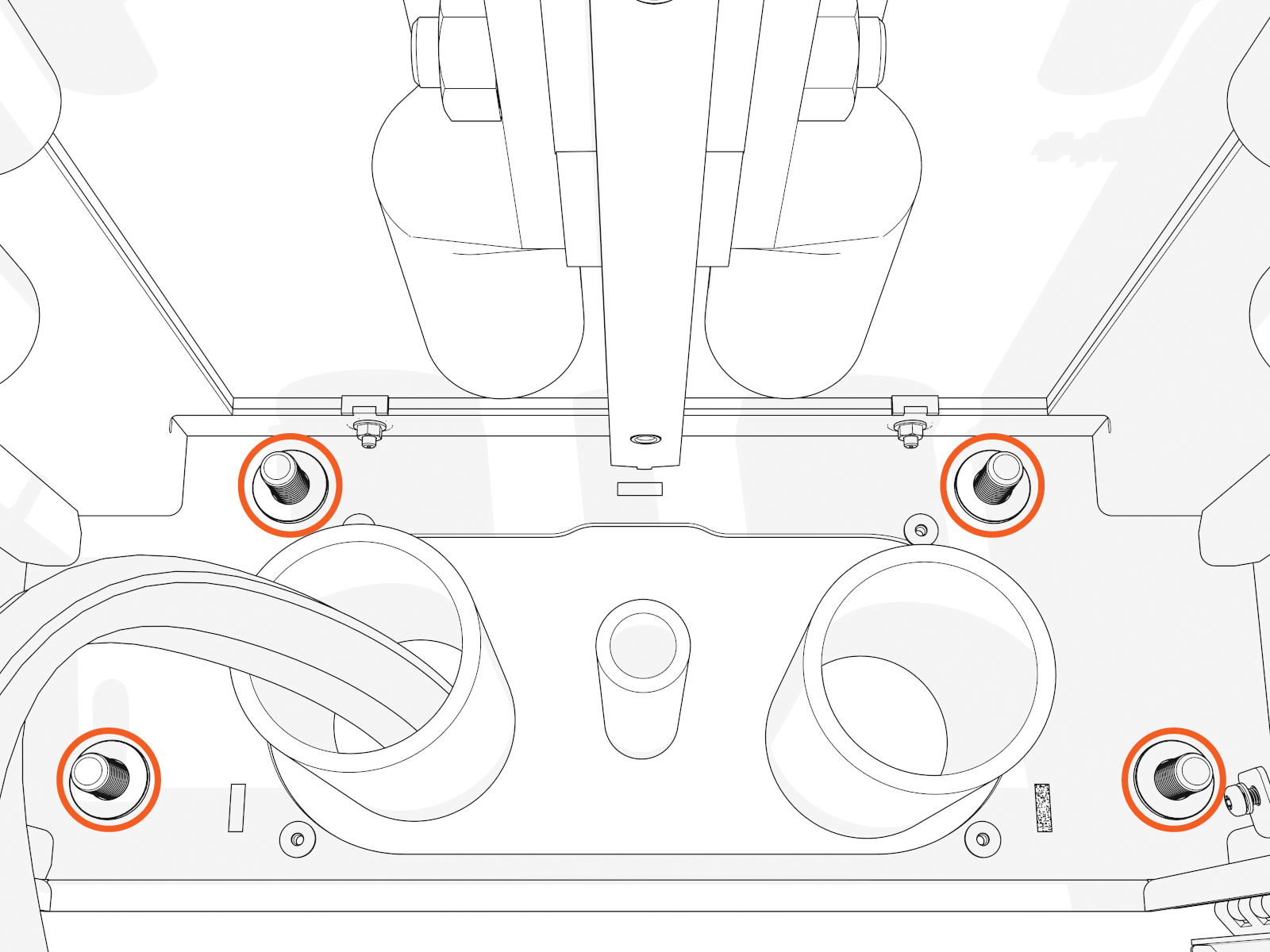
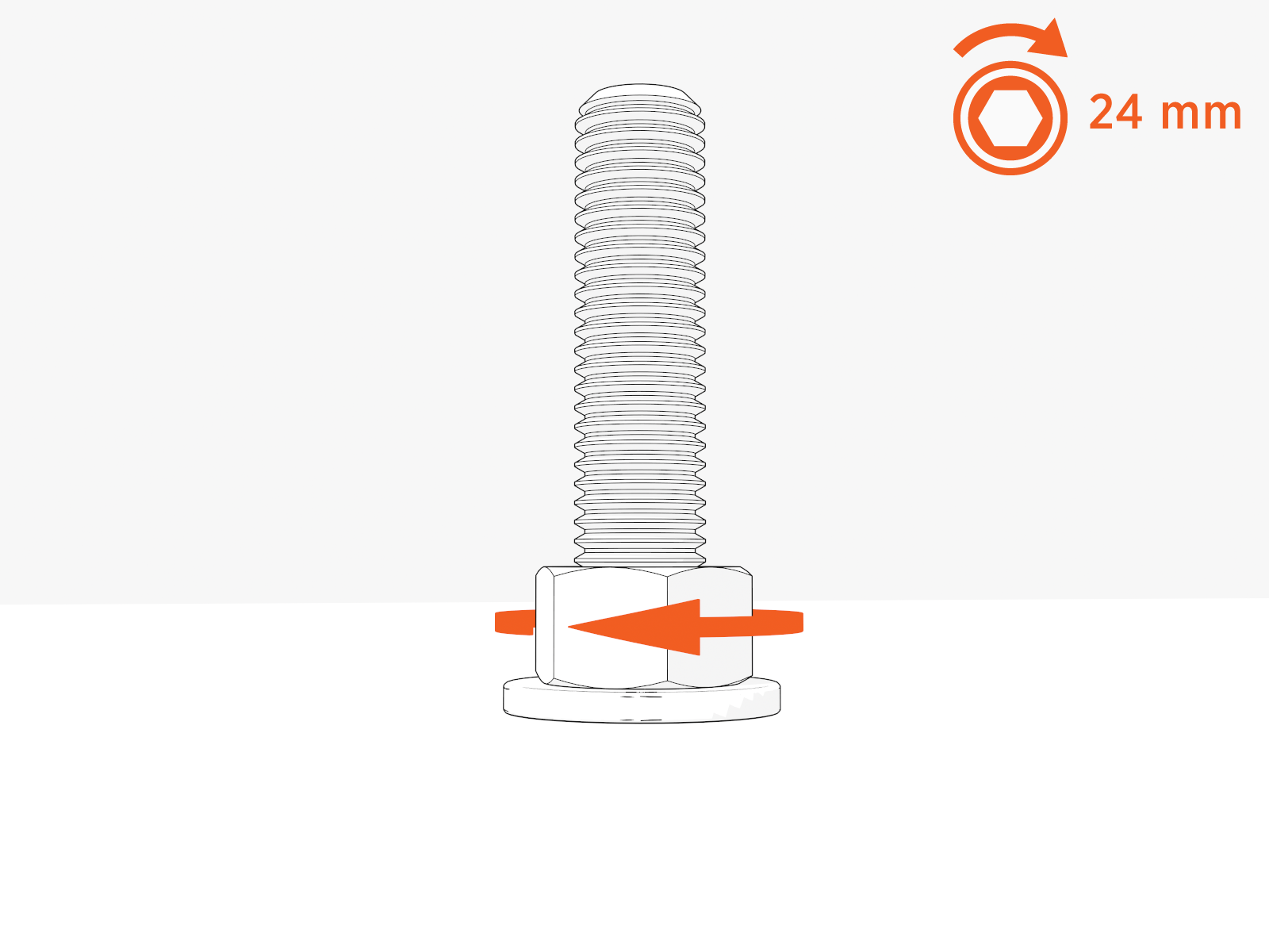
When the Power Link 1000 is fully seated, check that all sides are level (vertically and horizontally). If not, adjust three leveling nuts.
-
Partially install a washer and "top" nut onto each bolt by hand.
Do not tighten yet.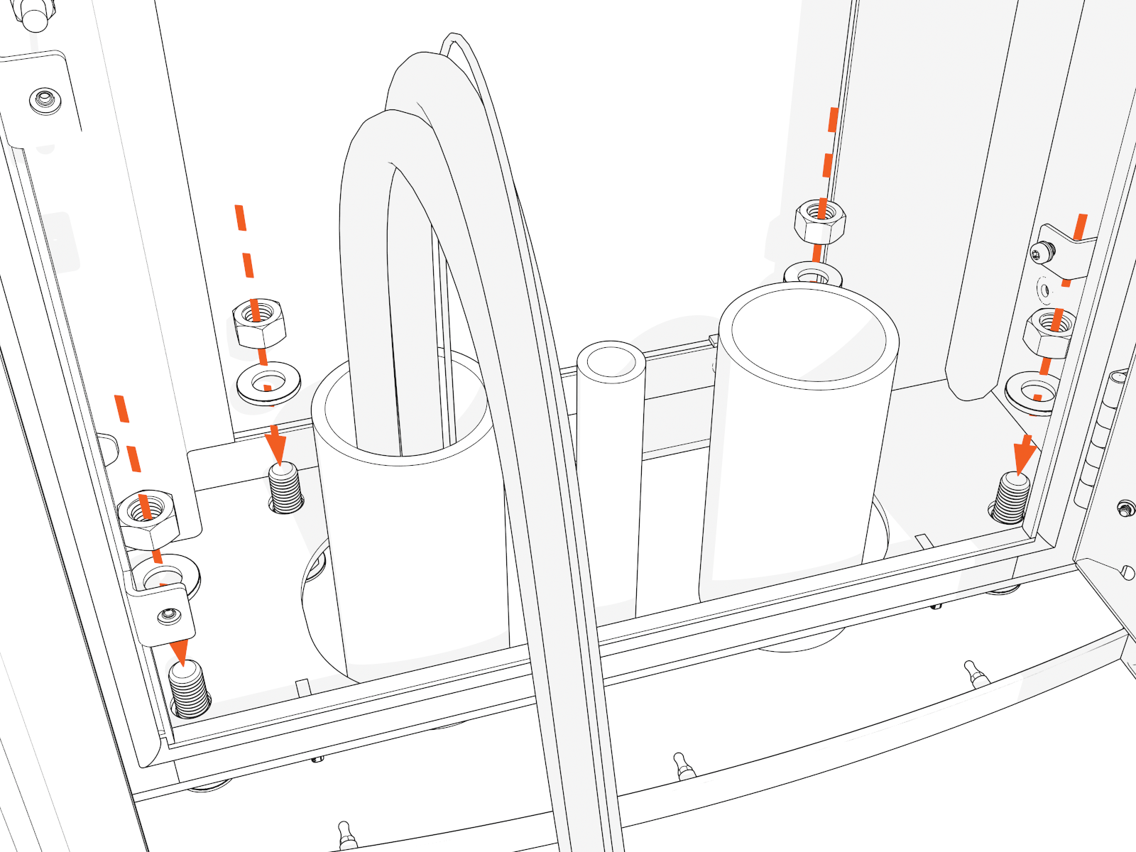
-
Recheck and adjust three leveling nuts.
-
When Power Link 1000 is level, rotate the fourth leveling nut until flush.
-
Torque the top nuts to 95 Nm (70 ft-lb).
-
Remove the lift straps and eye bolts.
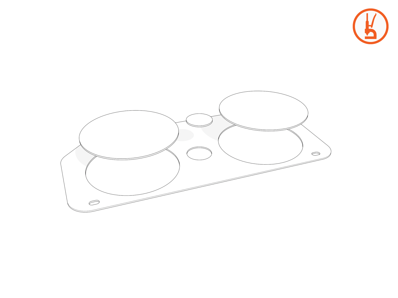
Gland Plate
To create openings in the gland plate, complete the following steps:
-
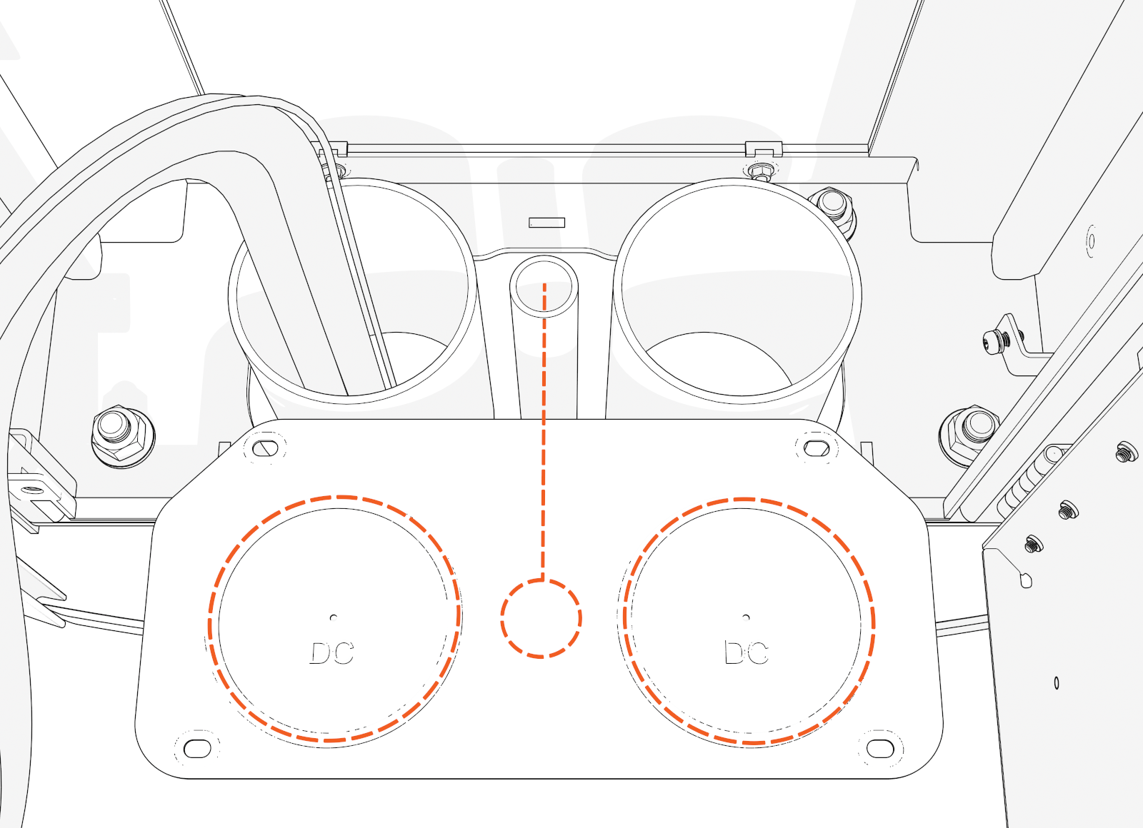
Check site drawings. Use a hydraulic hole punch to create openings in the gland plate for those conduits:
-
DC input conduits
-
Check for one or two DC conduits.
-
Use the gland plate pilot holes as a guide.
-
Punch out one or two larger openings.
-
-
48 V DC and Ethernet conduits
-
Check for one, two, or three conduits (middle of gland plate).
-
Punch out one, two, or three smaller opening(s).
You may have a different number of conduits.
-
-
Match the size of each conduit. Each opening must be large enough for the entire conduit to pass through.
-
Reposition the gland plate. Pull all conductors through the openings.
Do not reinstall the gland plate screws yet.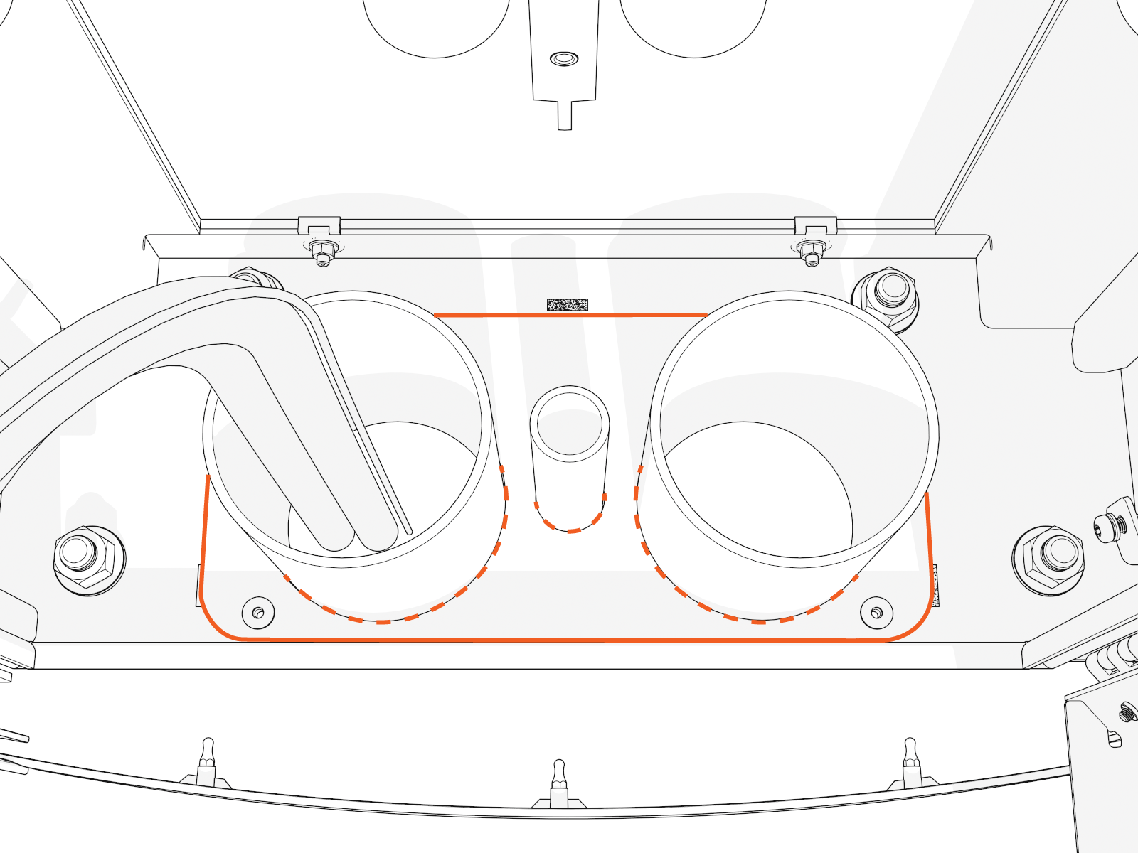
Connect Wires (Standard Pedestal)
To connect wires, complete the following steps:
- Before any procedure, disconnect the power.
- Follow local code and site lockout/tagout procedure to de-energize the station.
- Wait for energy to dissipate (approximately five minutes).
- Keep power off until all covers and panels are reinstalled and the work is complete.
-
Disconnect power at the site electrical panel.
Follow standard practice and local code to de-energize the applicable circuit and lock out/tag out the disconnect before proceeding.
-
Use a multimeter to test that the unit is de-energized.
-
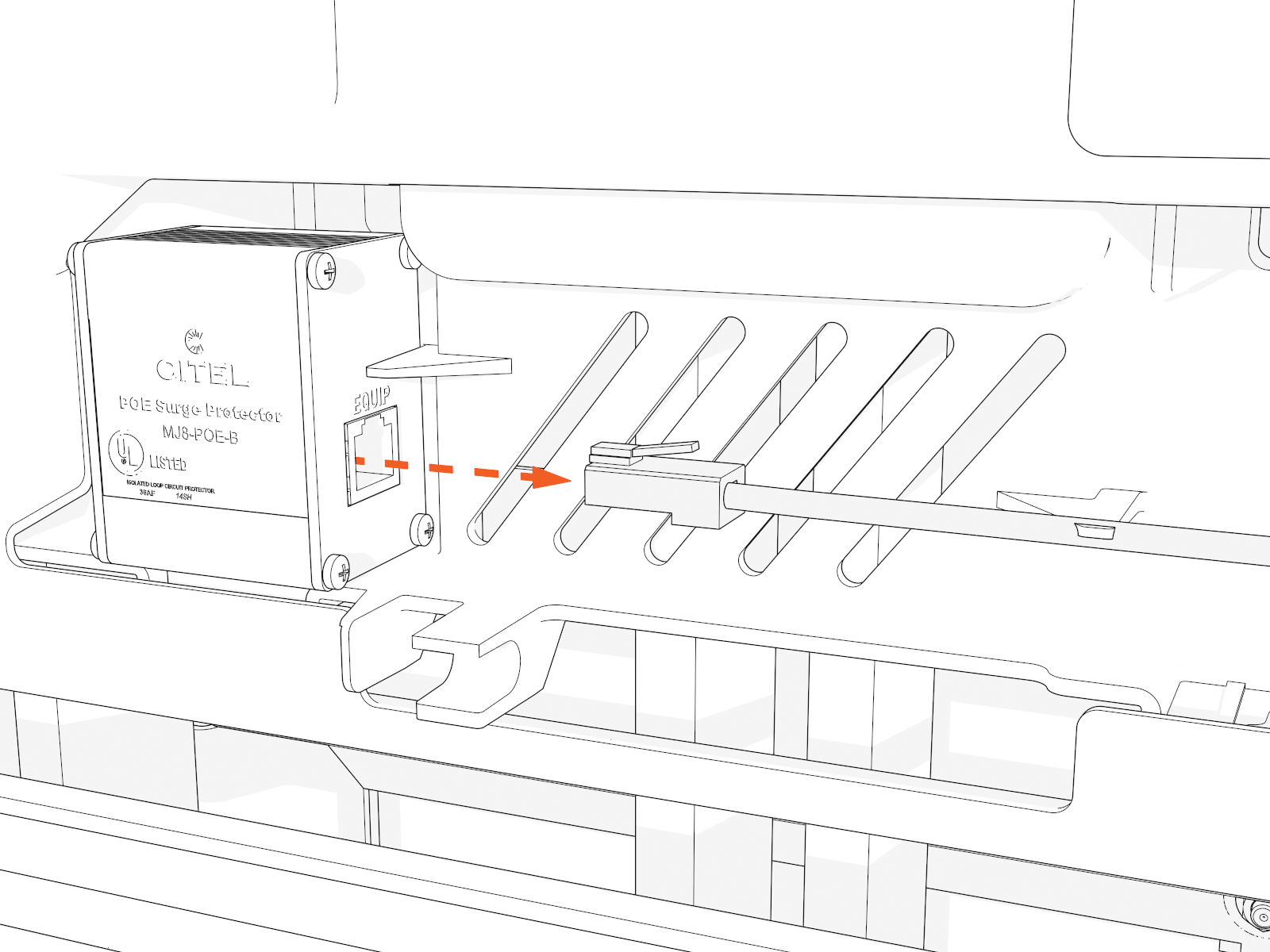
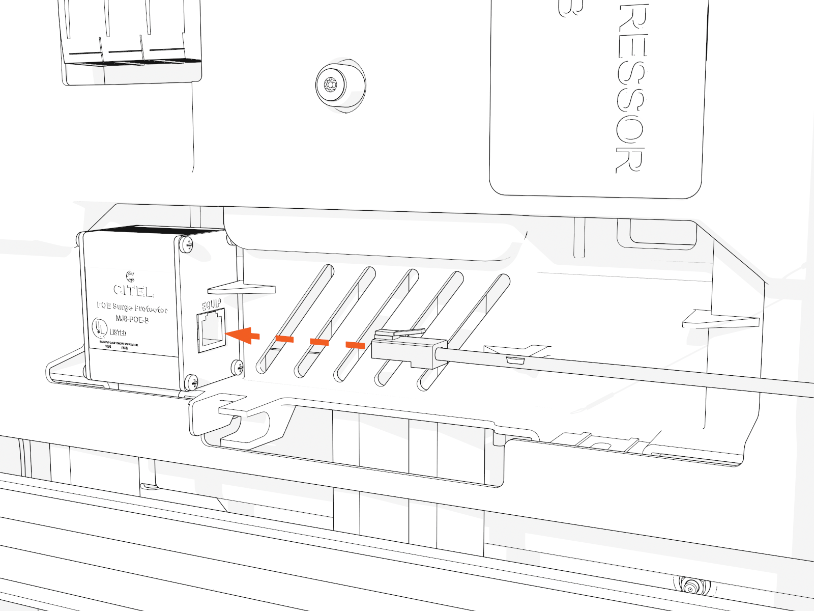
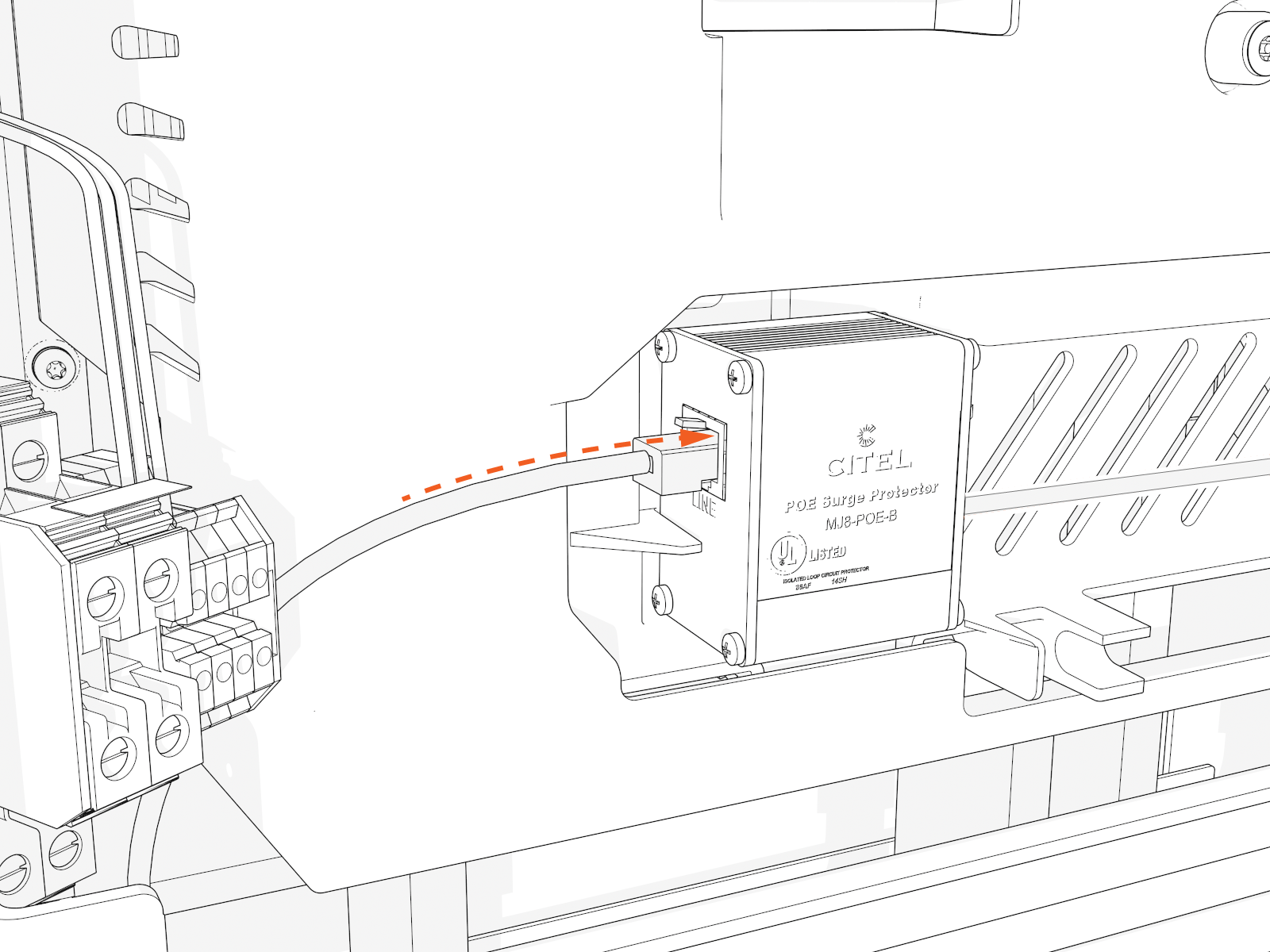
Disconnect the Ethernet cable from the Ethernet surge suppressor.
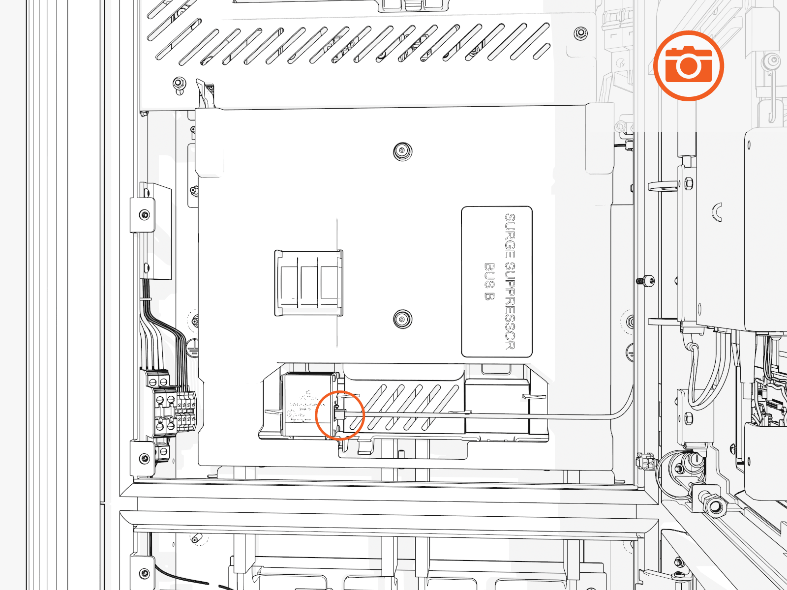
Take a photo or note to identify which port later.
-
Access the upper bus bars.
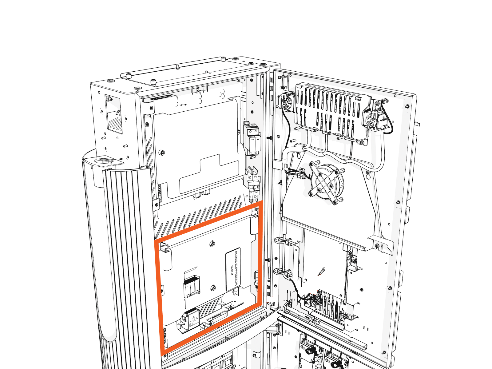
-
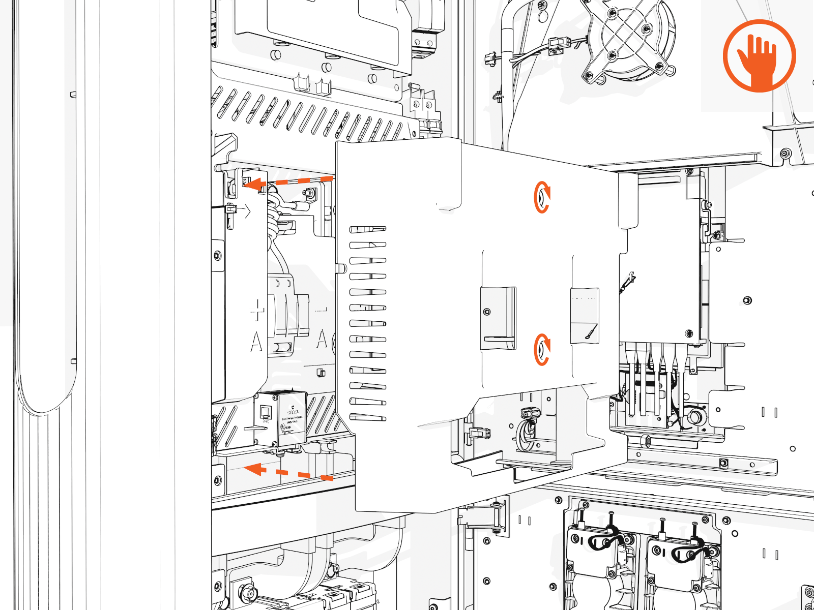
On the power plate cover, loosen the captive screws.
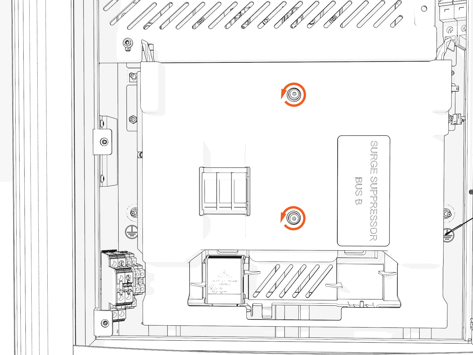
-
Remove the cover.
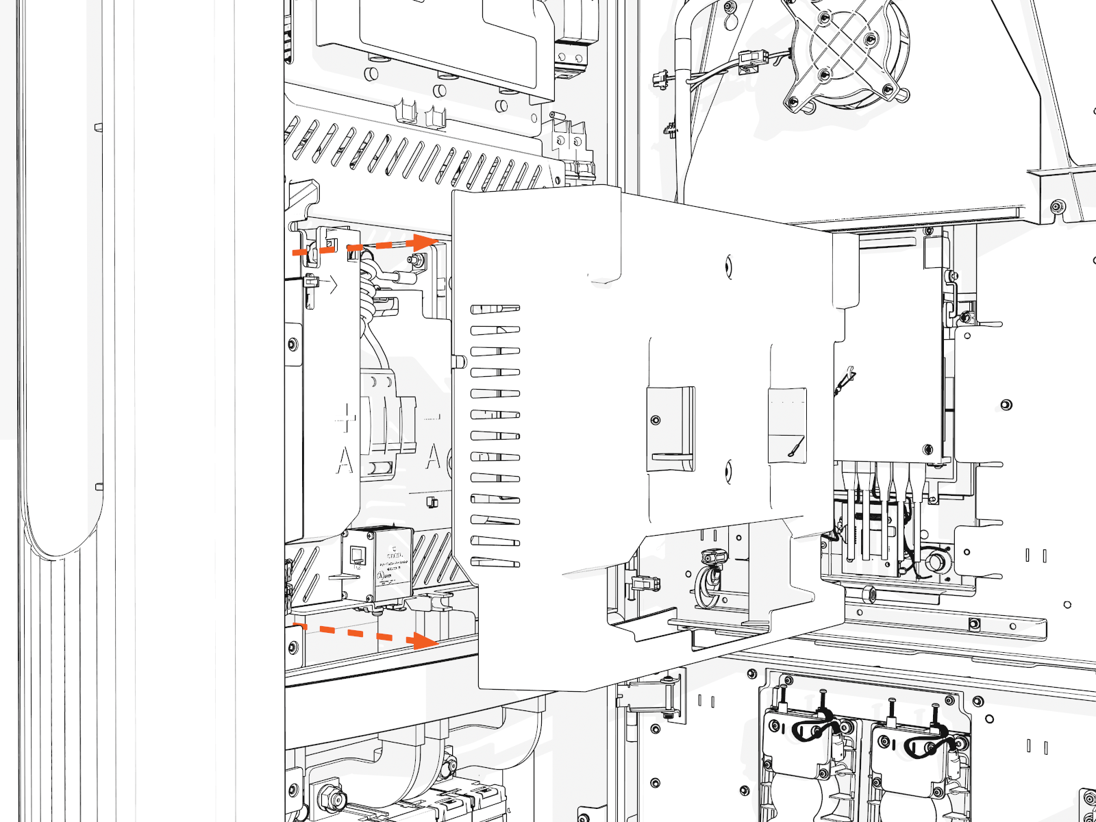
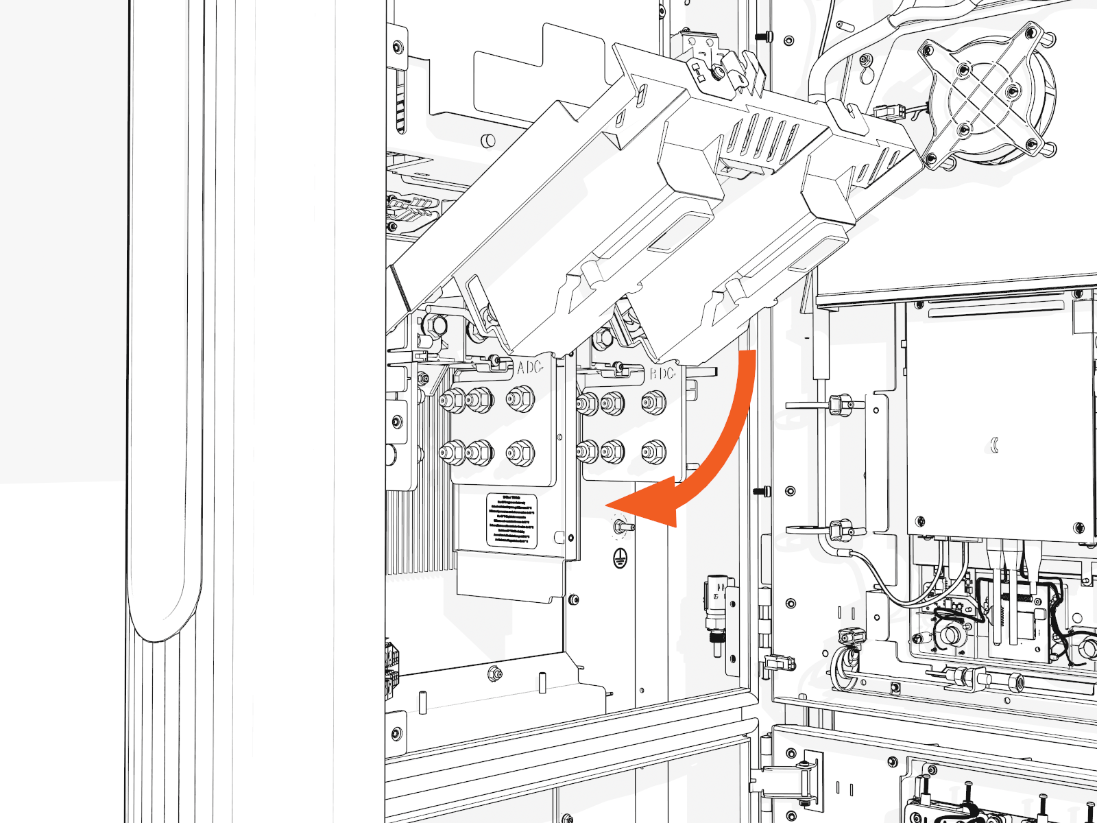
-
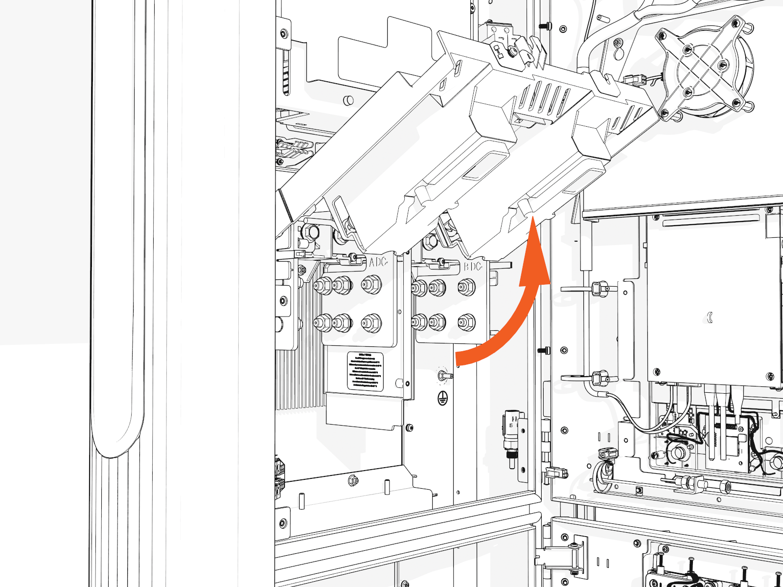
Release the tabs on the upper safety cover.
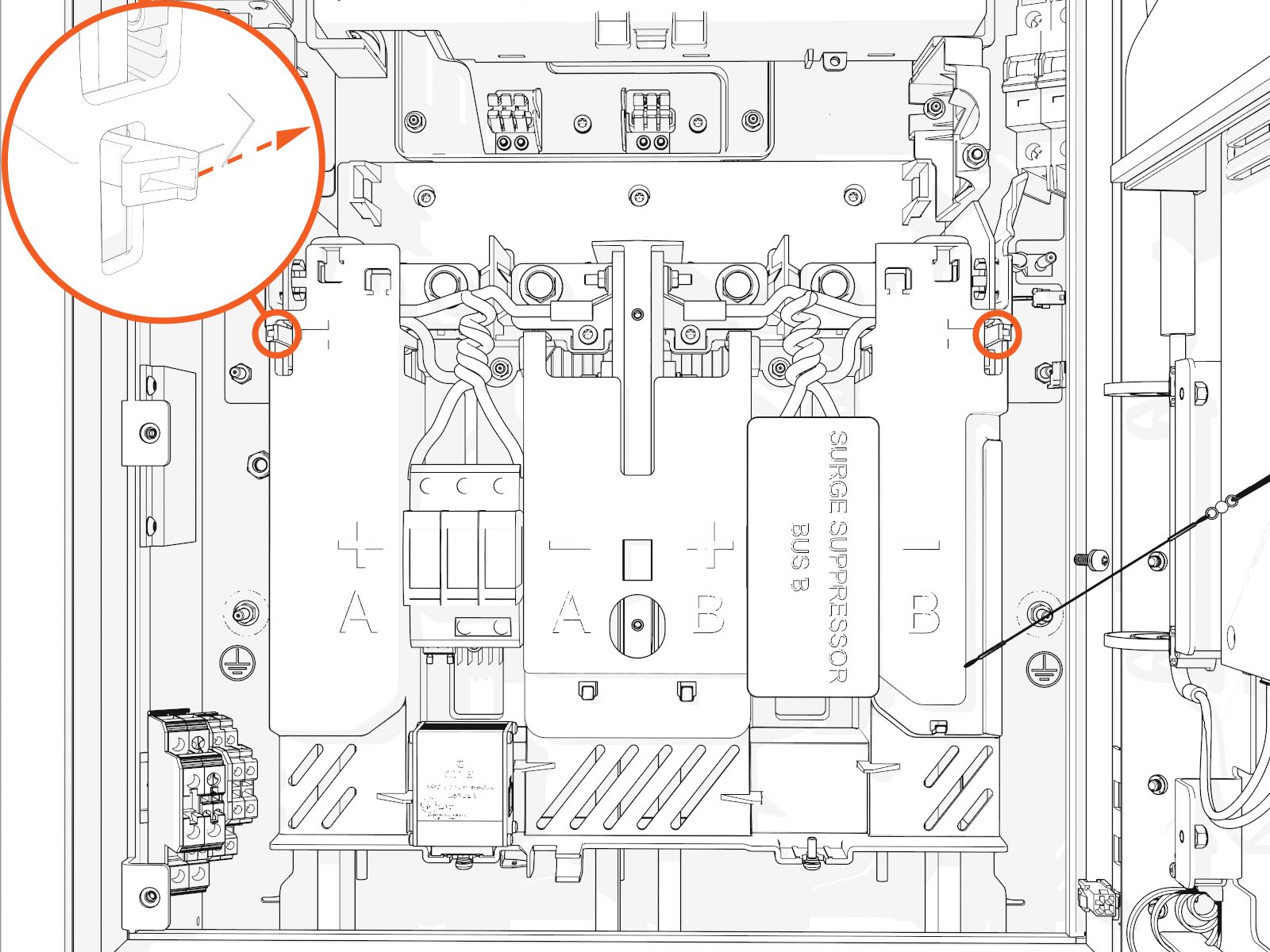
-
Lift up from the bottom until it locks in the open position.
Install DC Conductors and Lugs, and Ground Wire
To install DC conductors and lugs, and ground wires, follow the instructions below.
Prep for wire install
-
Ensure you have de-energized the applicable circuit and locked out/tagged out the disconnect according to standard practice and local code before proceeding.
-
Use a multimeter to test that power is off.
-
Route all conductors into the correct area within the cabinet.
Measure and cut
-
Loosely install lugs only (without the conductors) onto bus bars. Hand-tighten.
Use included bolts, washers, and nuts
-
Measure the length from each conductor to its corresponding lug.
Mark each conductor at the point where you will need to trim it.
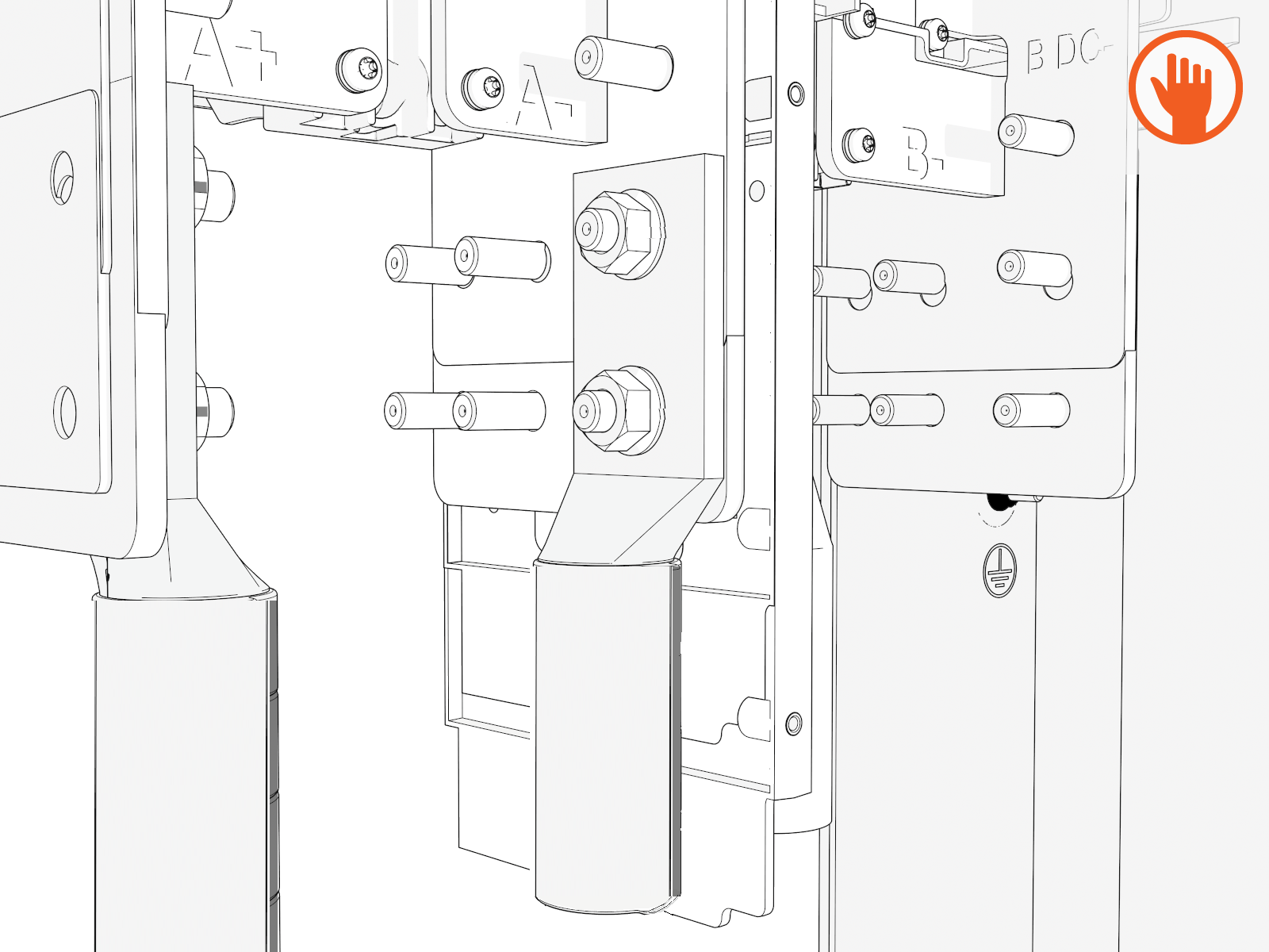
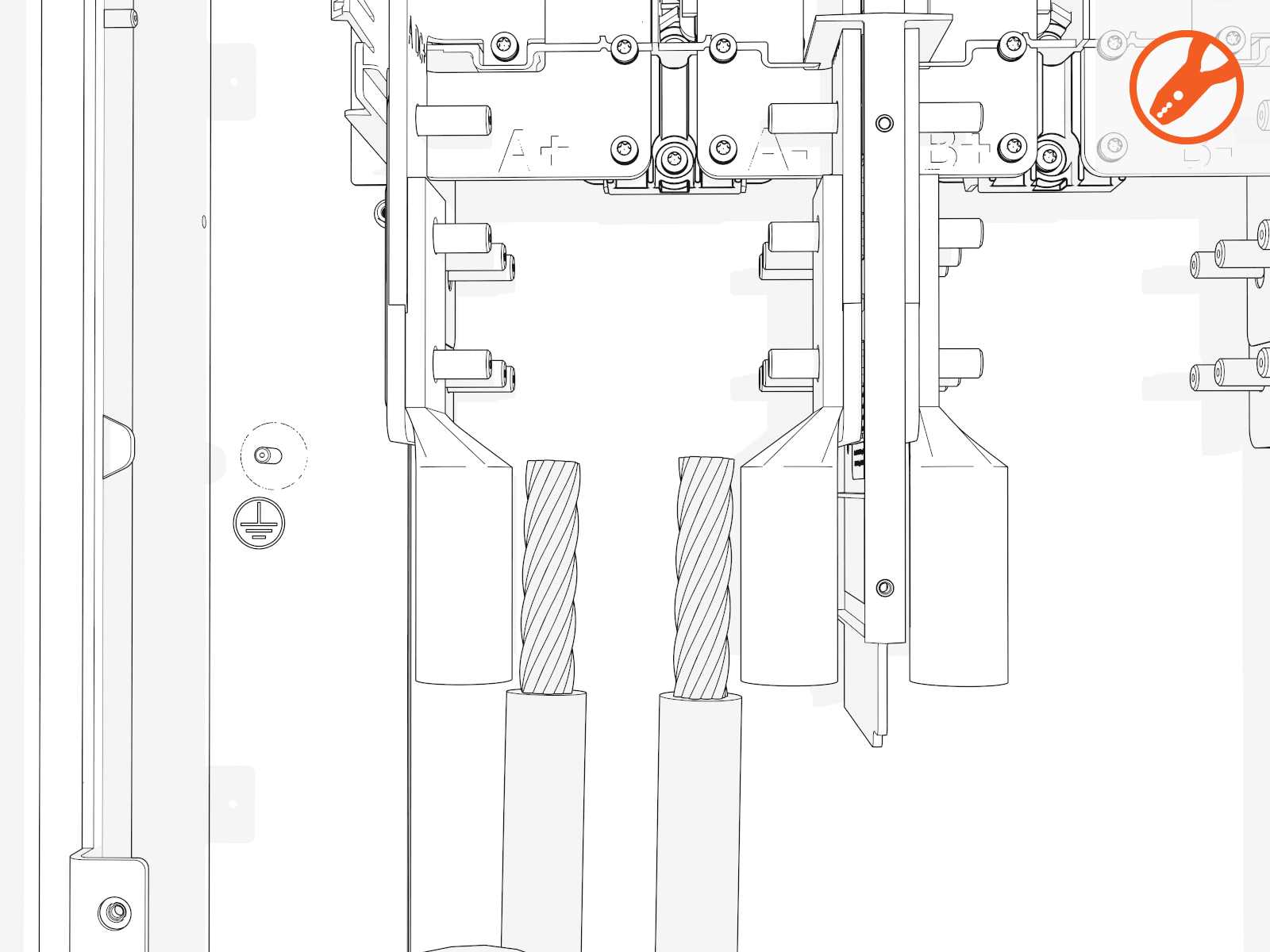
DC bus bars are marked in order from left to right:
Single Input Dual Input A+
A-
A+
A-
B+
B-
-
Strip and cut the conductors to the desired length.
Install DC lugs
-
Uninstall the lugs. Crimp a lug onto each conductor.
Use compression lugs with the specifications . Use the lug manufacturer’s tool and die. If required, heatshrink or tape the crimp area to meet local code.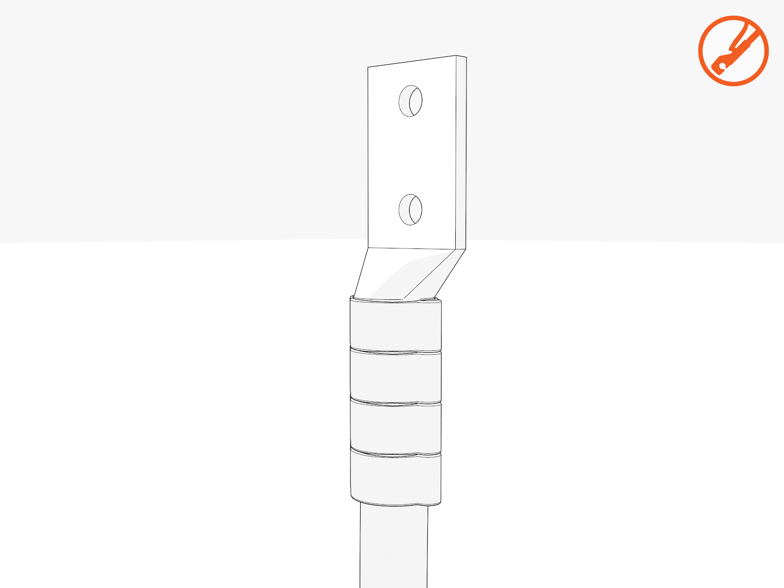
-
Land the DC lugs on the terminals. Torque nuts to 19 Nm (168 in-lb).
Fasteners are pretreated with dielectric grease.If using 500 kcmil conductors, you must use the back set of lugs to avoid interference with the surge suppressor panel.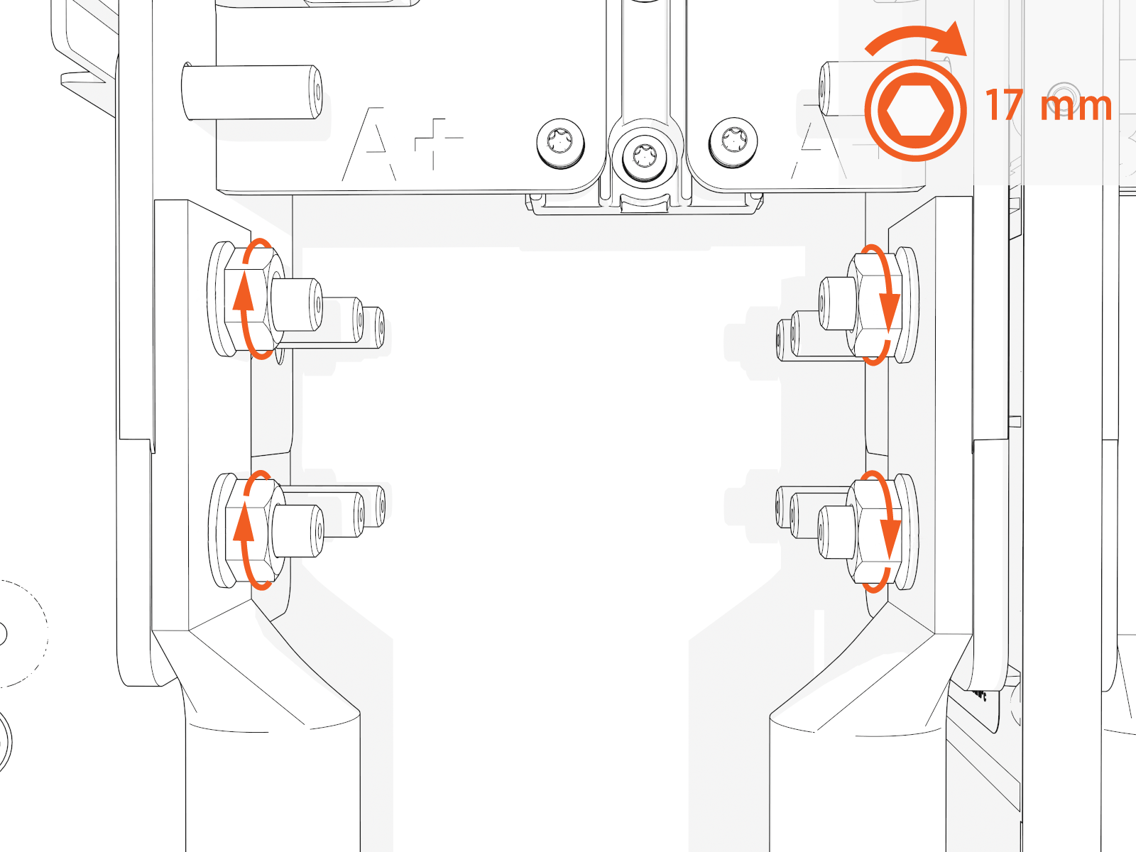
-
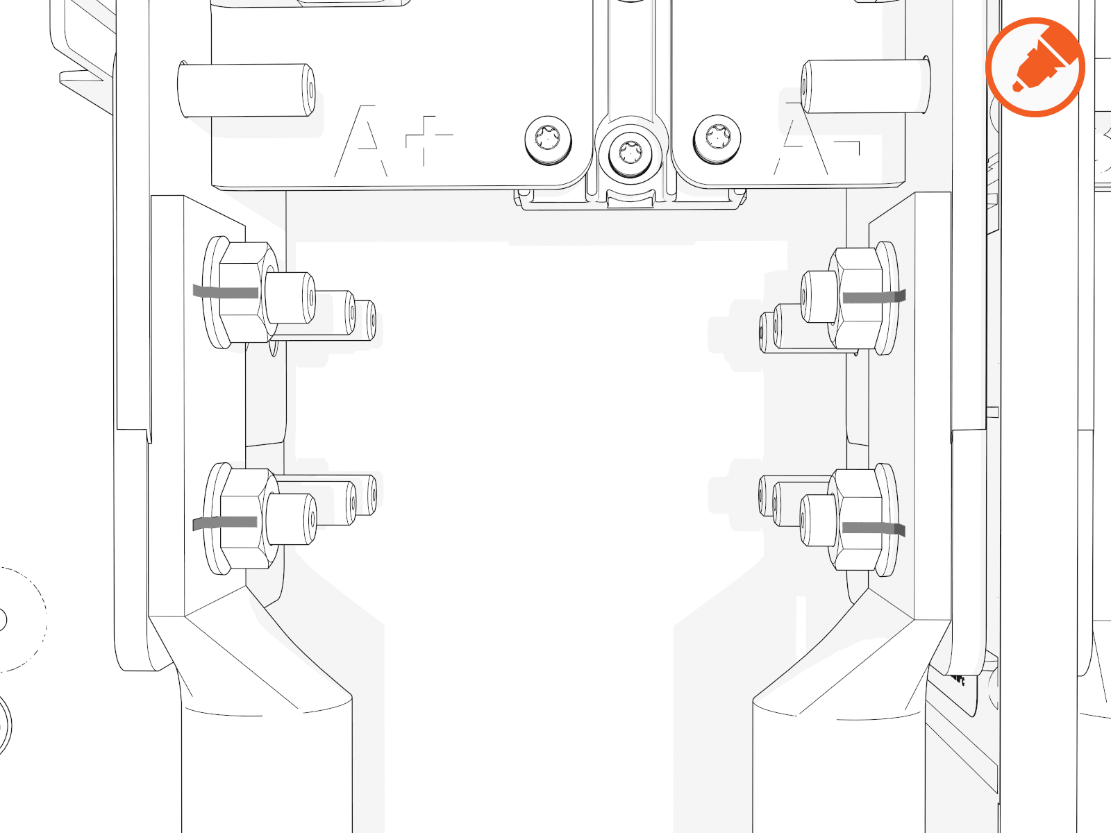
Mark all torqued power connections.
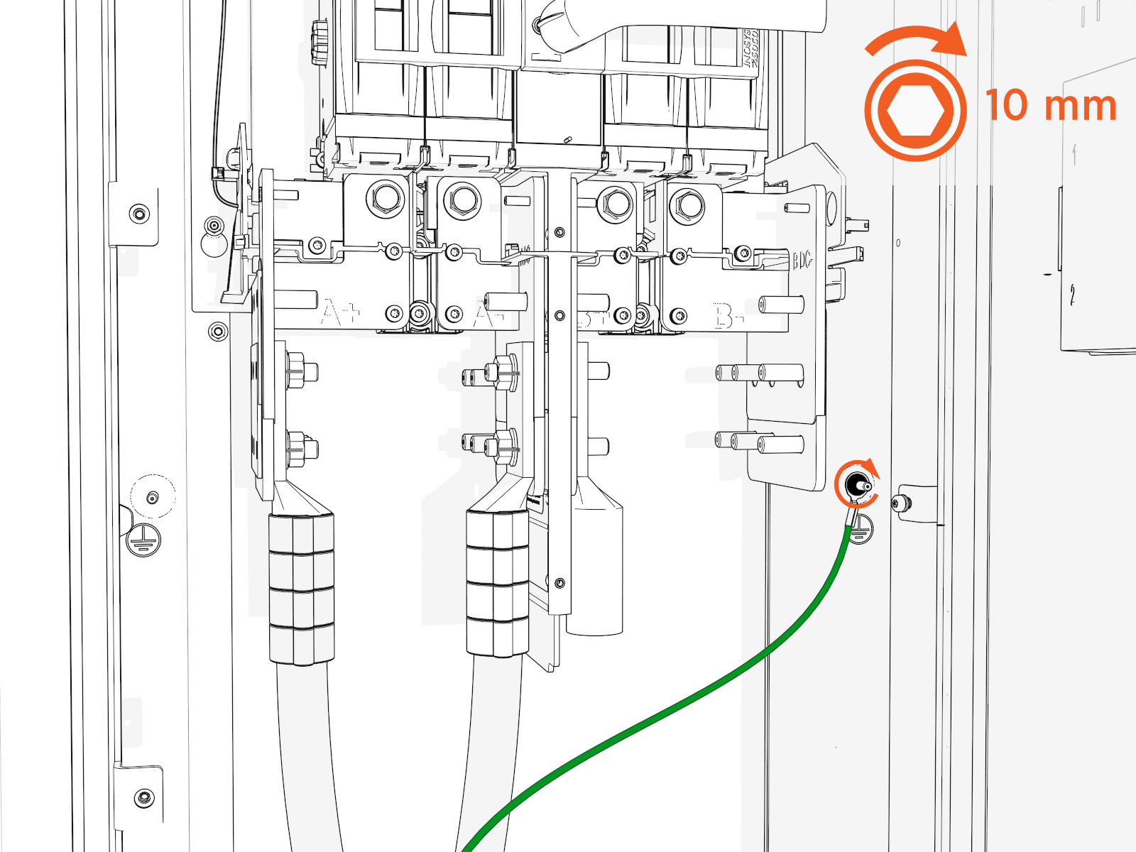
Install DC ground wire
-
Land the ground wire onto a ground stud. Torque to 7 Nm (60 in-lb).
-
If you are installing the "Overhead" Mounted configuration:
Tilt down the upper safety cover to close.
-
Position the power plate cover. Hand tighten the captive screws.
-
Reconnect Ethernet cable(s) to Ethernet surge suppressor into the same ports as before.
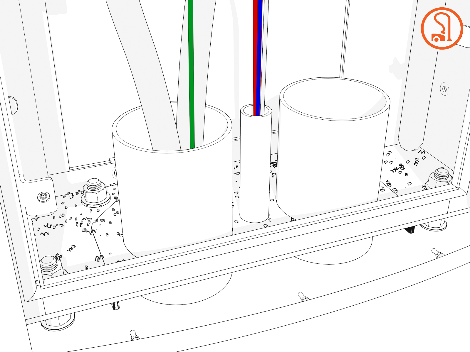
48 V DC Wiring
-
Check the 48 V DC wiring requirements in the site drawings:
48 V DC Wiring 48 V DC Wire Size
Conduit Size
Installation
16 mm2 (6 AWG
 American Wire Gauge)
21 mm (3/4 in)
Install two 48 V DC wires and one Ethernet cable into one conduit.
Use only copper conductor wire rated for 90 °C (194 °F).
-
Strip the 48 V DC wires.
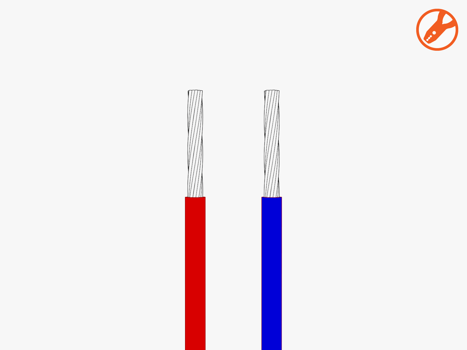
-
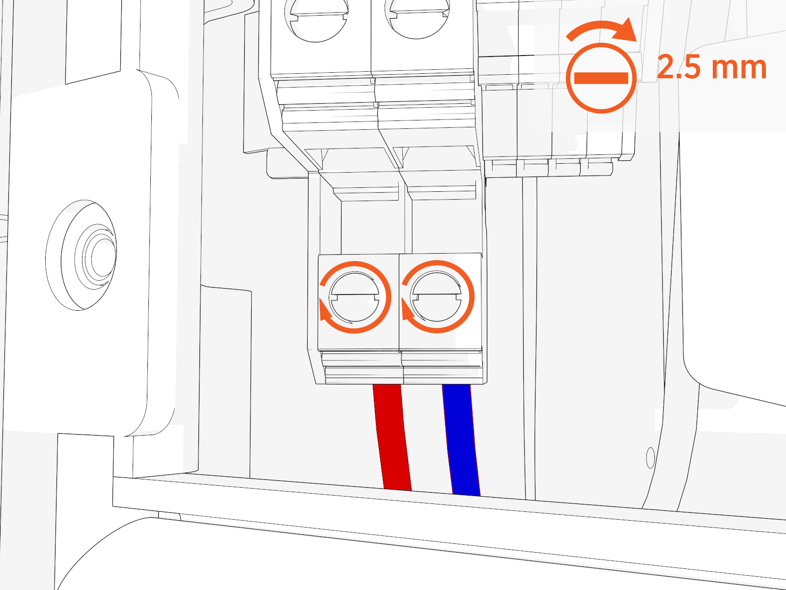
Loosen each terminal tab (upper cabinet, left side).
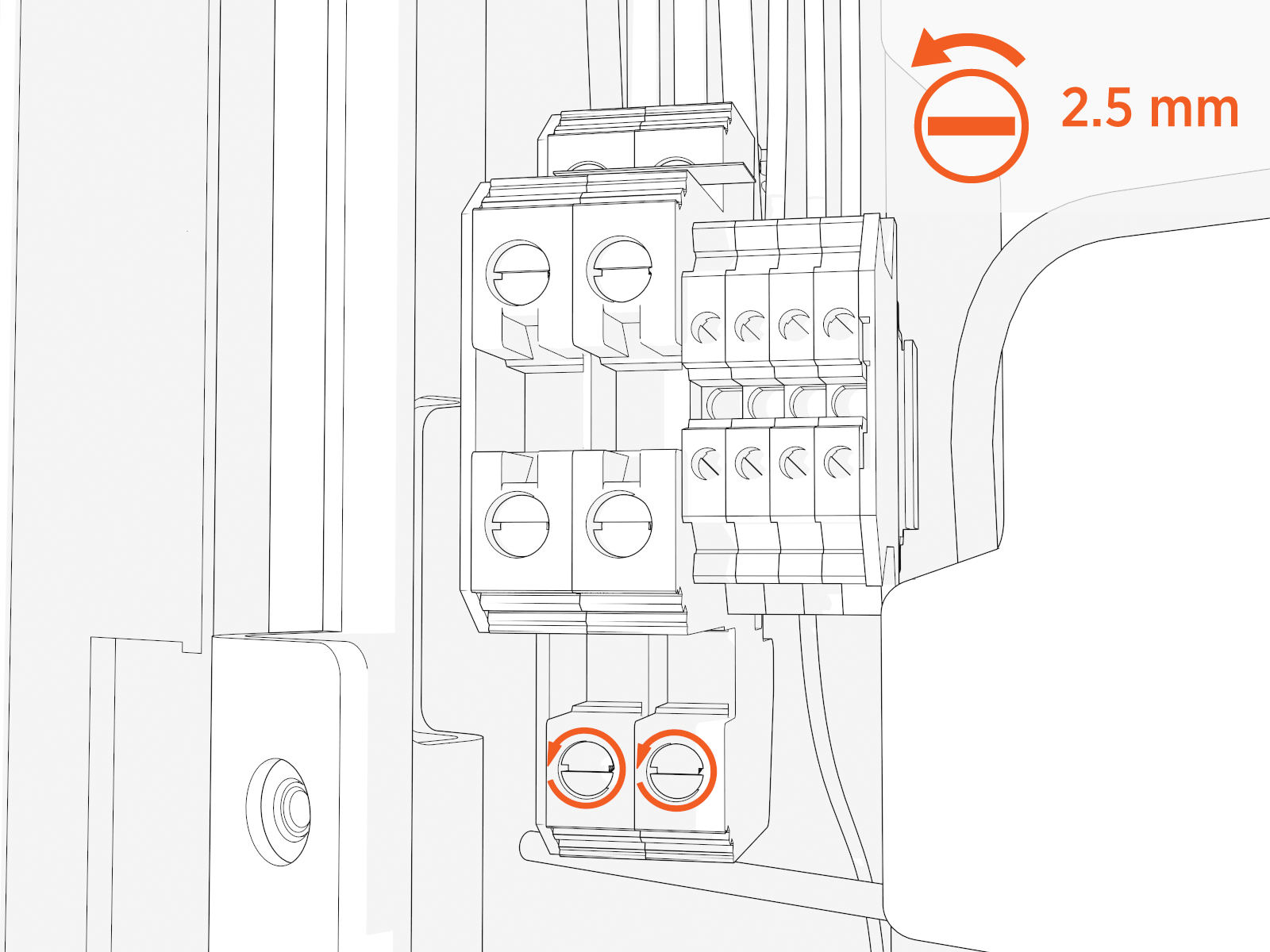
-
Seat the 48 V DC wires. Push-pull to test.
Cat6 STP Ethernet Cable
-
Trim the Cat6 STP
Shielded Twisted Pair Ethernet wires to length and allow for a service loop. Terminate both ends. -
Field crimp a shielded connector onto each Cat6 STP
Shielded Twisted Pair Ethernet wire. Use a straight-through T568B pattern.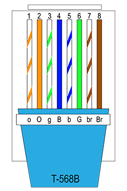 Do not connect the shield wire here at the Power Link 1000 termination.
 -
Test each Ethernet wire for functionality.
-
Identify which blue surge suppressors already have cables in the line-out (right) positions. Connect the Ethernet connectors to those surge suppressors at the line-in (left) positions. Push-pull to test.
Install Ethernet to USB Kit
If the site plan indicates the Power Link 1000 must be configured with a hardwire Ethernet connection to a network server, follow procedures in this section to install the Ethernet to USB![]() Universal Serial Bus Kit and the hardwire connection.
Universal Serial Bus Kit and the hardwire connection.
Mount Ethernet to USB Module
To mount Ethernet to USB![]() Universal Serial Bus module, complete the following steps:
Universal Serial Bus module, complete the following steps:
-
Unpack the Ethernet to USB
Universal Serial Bus Kit. Confirm all parts listed below are present.For any missing component, contact chargepoint.com/support.

-
Ethernet to USB
Universal Serial Bus module -
M5 star washer nuts (x2)
-
Zip ties (x5)
-
USB
Universal Serial Bus 3.0 Type B to Type C cable
-
-
Locate a grounding stud on the Power Link 1000 frame.

-
Install one of the provided M5 star washer nuts partially onto the stud. Thread the nut only halfway onto the stud.

-
Mount the Ethernet to USB
Universal Serial Bus module onto the stud. Slide the module down to secure the keyhole tab to the stud.
-
Torque the nut to 4.5 Nm (40 in-lb).

-
Plug the USB
Universal Serial Bus-B end of the USB Universal Serial Bus cable into the module.
-
Route the cable through the door cable guide and along the main cable harness to the Control and Communication Module (CCOM
Control and Communications Module) located on the upper front door. located on the upper front door.")
-
Connect the cable to the CCOM
Control and Communications Module. 
-
Secure the USB
Universal Serial Bus cable to the existing cable tie guides.
-
If needed, use the provided zip ties to secure the USB
Universal Serial Bus cable to the main cable harness.-
Ensure that the door can open and close without pinching or pulling of any cables.
-
Ensure that the USB
Universal Serial Bus cable does not touch the HV DC High Voltage Direct Current wires when the door is closed.
-
Install Ethernet Cable
To install Ethernet cable, complete the following steps:
-
Pull the hardwire Ethernet cable into the enclosure and route it through existing cable guides to reach the Ethernet to USB
Universal Serial Bus module. Cut to length, allowing for a service loop.
-
Field crimp an RJ45 connector onto the Ethernet cable. Use straight-through T568B pattern.
Do not ground the shield at this end of the Ethernet cable. Ground the shield at the end of the Ethernet cable that connects to the network server.

-
Test the Ethernet cable for functionality.

-
Connect the Ethernet cable to the Ethernet to USB
Universal Serial Bus module.
-
Route and plug the other end of the Ethernet cable into the network server.
Secure and Seal Gland Plate
To secure and seal the gland plate, complete the following steps:
-
Vacuum all wire ends and metal shavings.
-
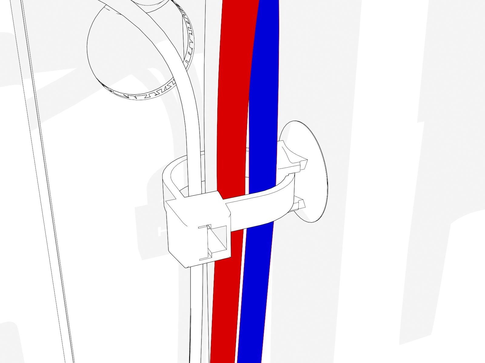
Secure wiring with clips as needed.
-
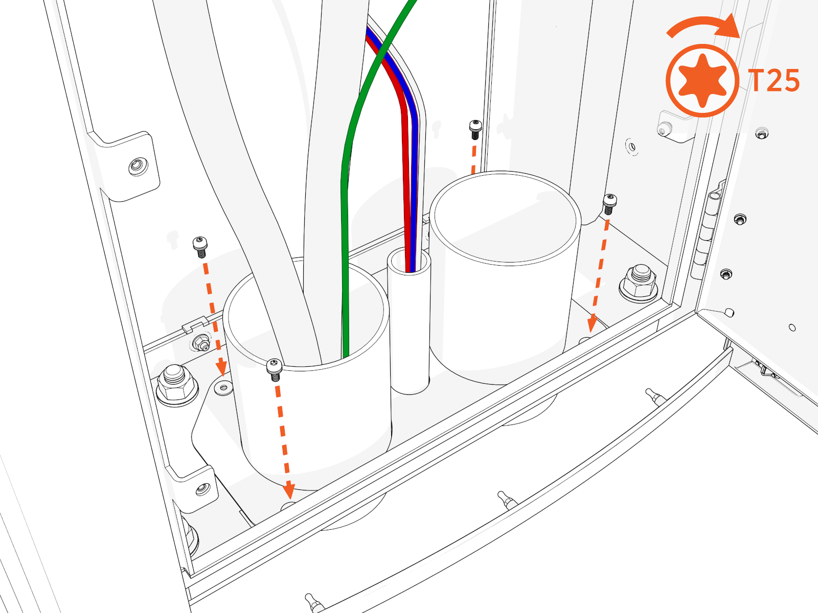
Align the gland plate and install screws.
-
Use duct seal compound to seal inside conduit openings.
-
Seal the gland plate around and to each conduit.
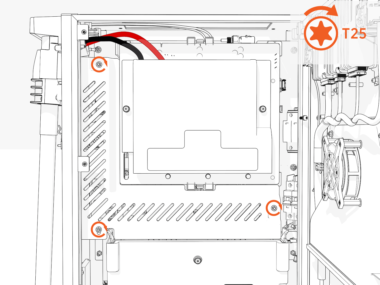
Reinstall Lower Safety Panel (if applicable)
To reinstall the lower safety panel, complete the following steps:
-
Slide in the panel behind the slots on the left.

-
Install screws (x3) (use T25 security screwdriver) on the right side. Torque to 2.8 Nm (25 in-lb).

Install DC Smart Cable
To install DC smart cable, follow the instructions below:
- Before any procedure, disconnect the power.
- Follow local code and site lockout/tagout procedure to de-energize the station.
- Wait for energy to dissipate (approximately five minutes).
- Keep power off until all covers and panels are reinstalled and the work is complete.
Installing a cable cap follows a similar process to installing a DC smart cable but only requires attaching the grounding lug to the machine shoulder; and connecting the 4-pin 48V terminal and RJ-45 communications connector.
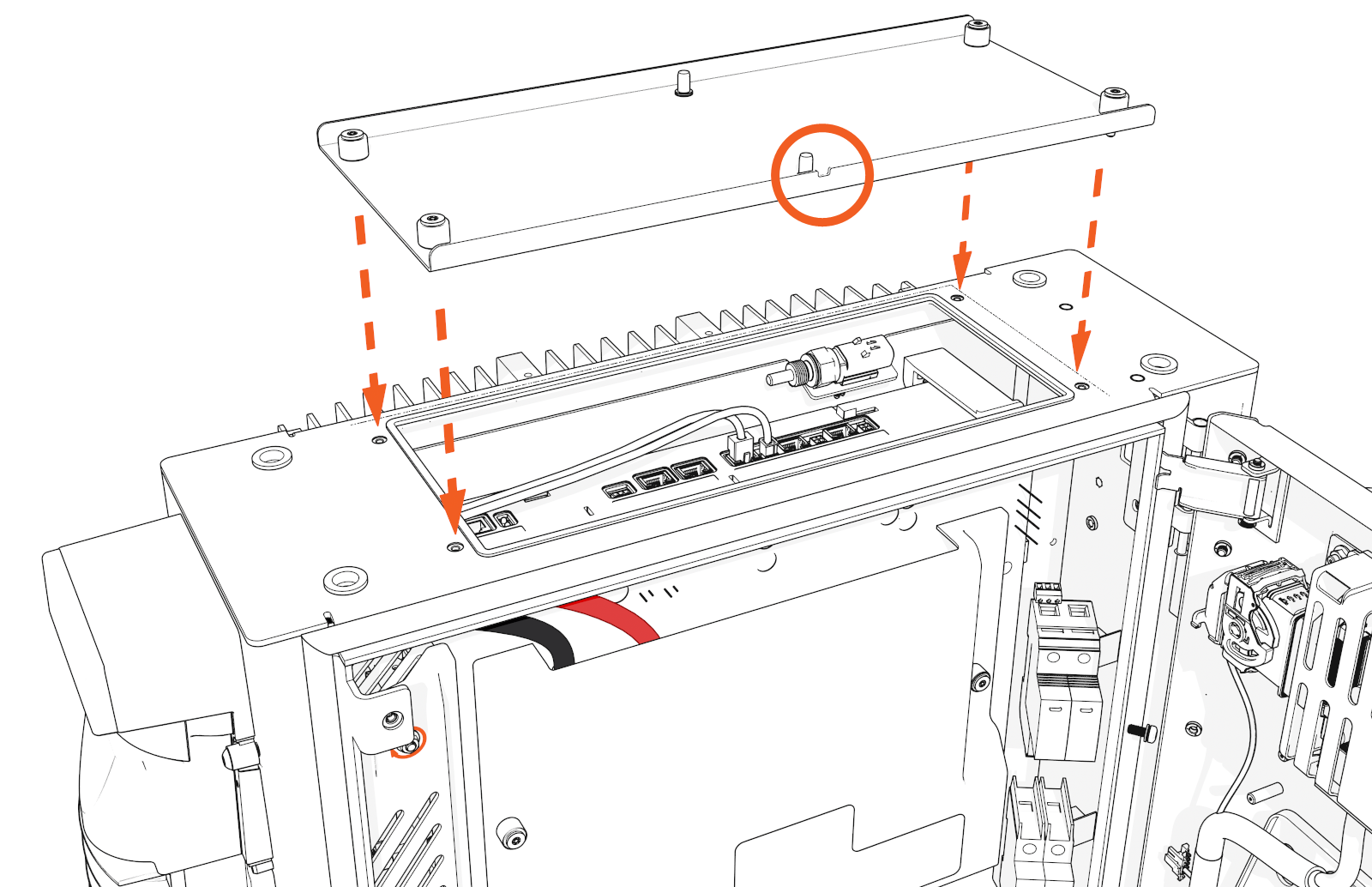
Remove Safety Cover and Top Access Panel
-
Loosen (do not unscrew completely) the two screws and slightly slide the safety cover up to remove it.
The + and - signs on the safety cover indicate the DC lug landing locations for positive (i.e., red color) and negative (i.e., black color) wires respectively.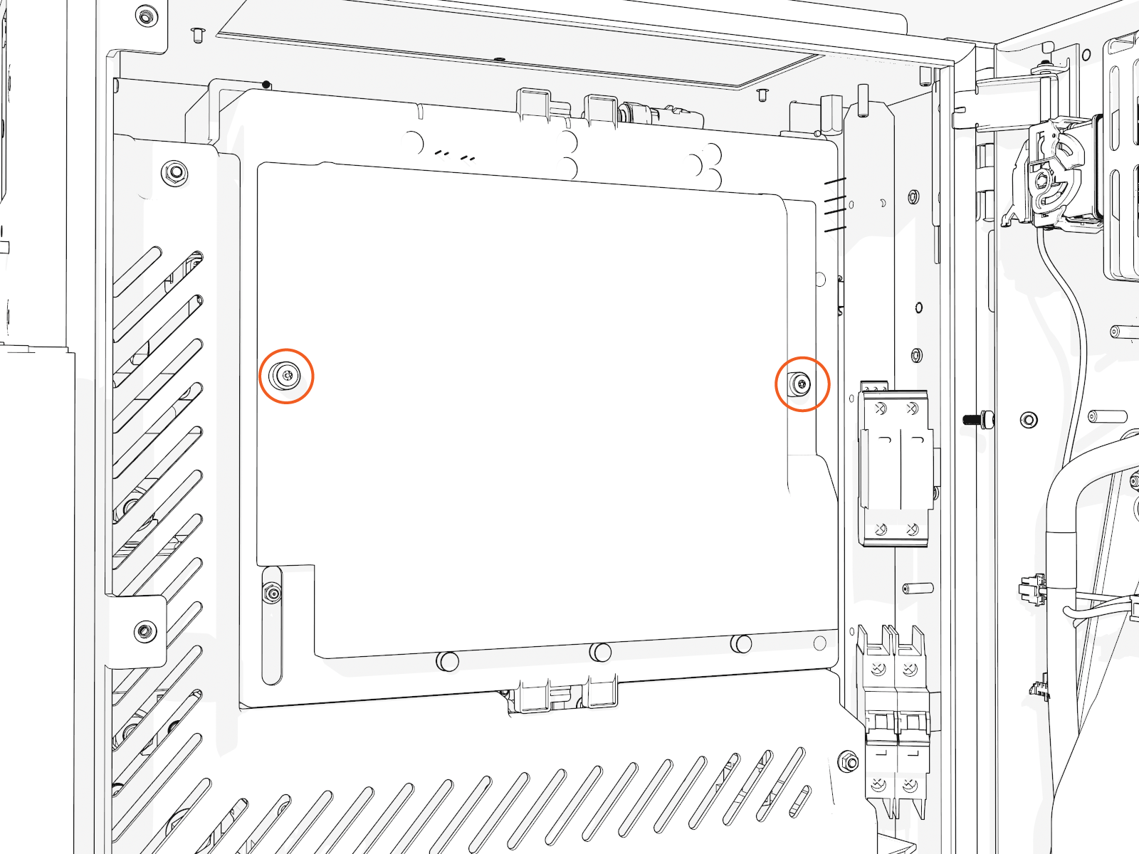
-
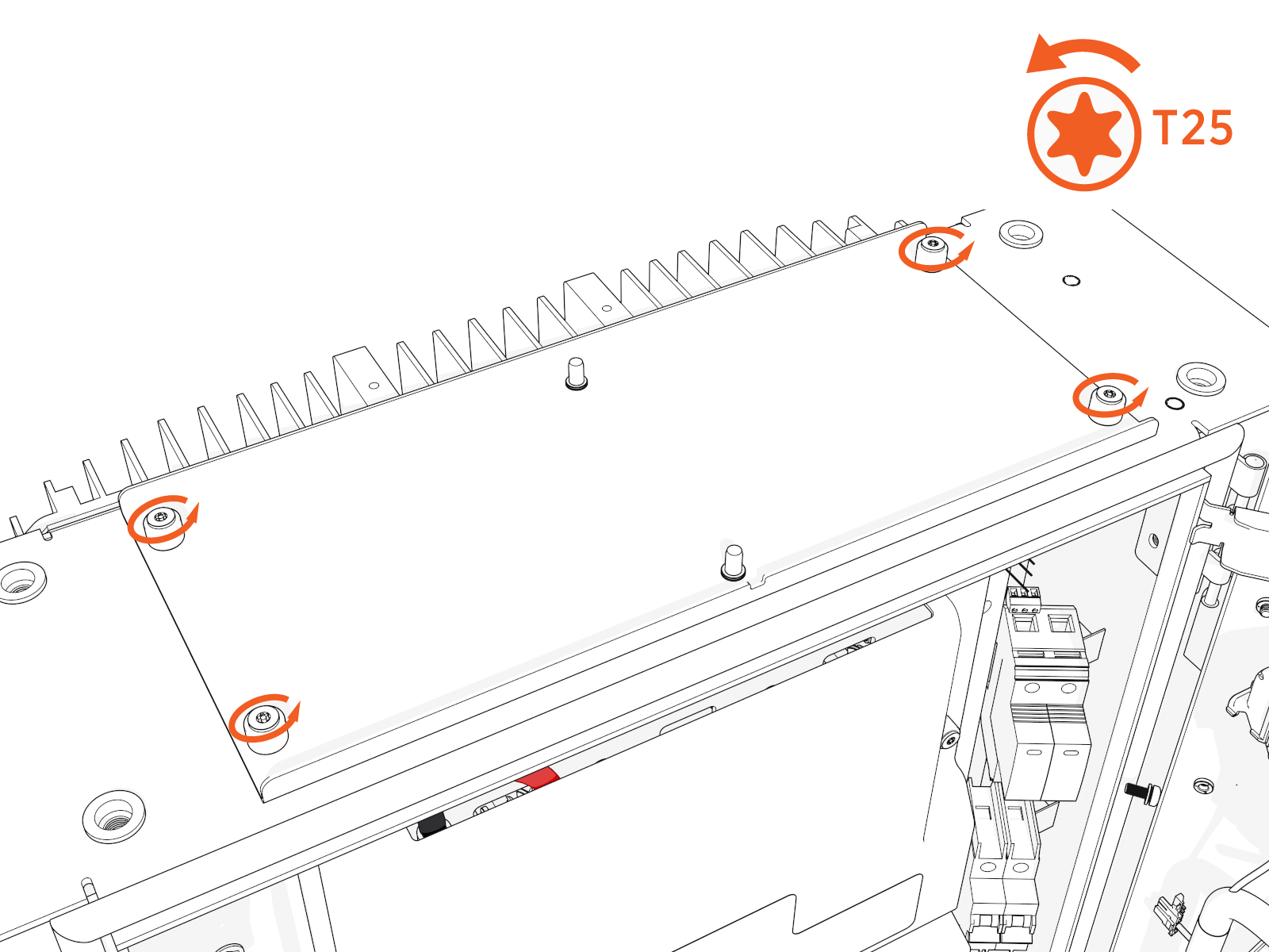
Position a stepladder so you can reach the top access panel.
-
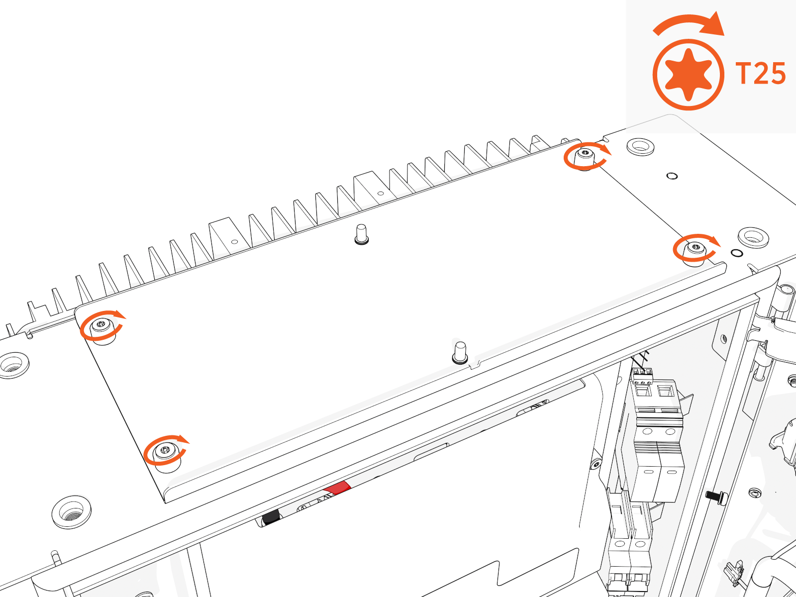
Loosen captive screws and lift off the panel.
Route Into Cabinet
-
Unwrap the charging cable.
Do not unwrap the cable handle to prevent it from getting scratched during the install process.
-
Route the connectors, DC smart cables and lugs, ferrite ring, and ground wire into the upper cabinet through the opening behind the cable housing.

Tilt the ferrite ring to fit.
-
If you removed the zip tie, attach a removable zip tie to the cables and ferrite ring.

Cable Housing
Align the cable housing onto the pegs. Torque to 4.5 Nm (40 in-lb).
Hold or clamp the cable housing in position.

Ground Wire, 48 V Power, and Ethernet
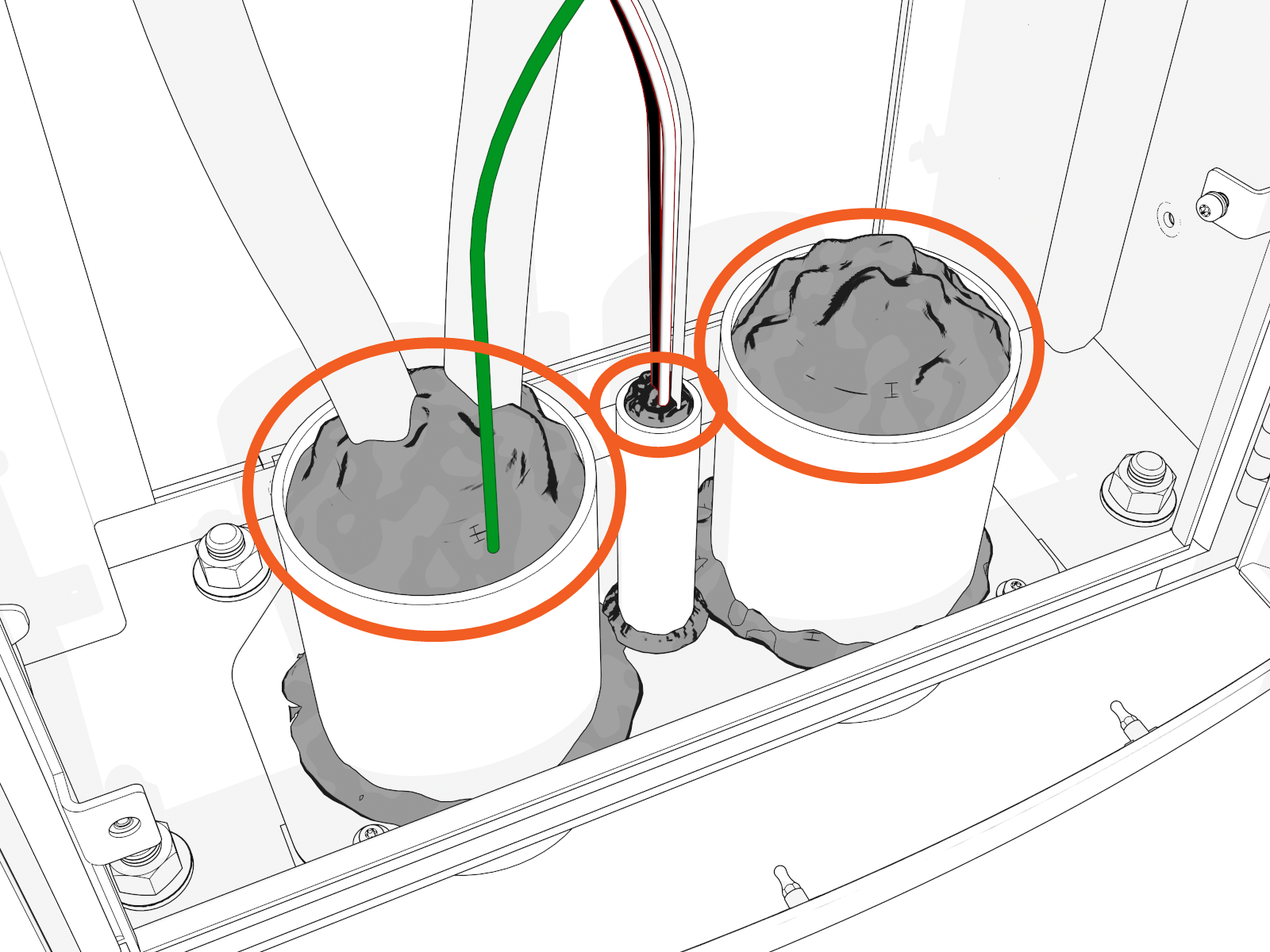
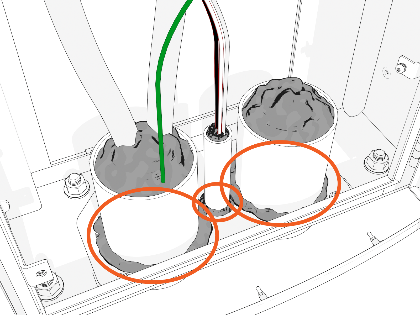
-
Locate the bolt near the cable housing. Install two ground wires for each charging cable. Secure the wires with a nut. Torque to 5.6 Nm (50 in-lb).


-
Locate the right and left wire harness. Connect one 48 V four-pin power connector to each.

-
If you switch connector ports, you could cause charging cable misidentification or disrupt status reporting between the local system and the ChargePoint Cloud Dashboard.
-
If you don't attach the lugs to their correct plate locations, you could reverse positive (red) and negative (black) polarity. This could damage the station or vehicle.
-
-
Plug the RJ45 Ethernet connectors from the left and right charging cables into RJ45 couplers on the left and right side respectively.

DC Lugs and Nuts
-
Land each positive and negative DC lug with a nut on the correct plate.
Torque to 5.6 Nm (50 in-lb).
Ensure that the cable pigtails (i.e., loose ends) crimped into a lug are not rubbing against the lug landing plate.
-
Install either four DC lugs for each charging cable of 350 A or two DC lugs for each charging cable of 250 A or less.
350 A:

250 A or less:

You must install the charging cable lug to either a left or right plate corresponding to the left or right charging cable.
Left and Right Charging Cables

-
Left charging cable
-
Right charging cable
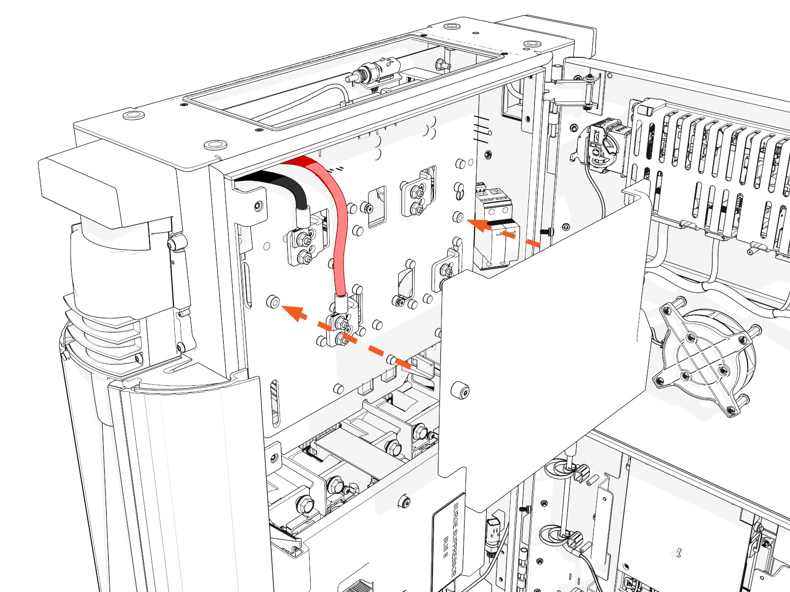
Red DC Cables to Positive Connectors

You must install each charging cable lug to either an upper or a lower plate to maintain the correct negative (black) or positive (red) polarity.
Before work, take a picture of which cable tab plugs into which slot on the contactor assembly. Cables are color-coded (black is negative, red is positive). Color codes are different for each installed charge connector type. It is critical that the cables are reattached to their original locations.
-
CHAdeMO has white and black color codes whereas NACS
North American Charging Standard, CCS1, and CCS2 have red and black color codes. -
It is easiest to unfasten all cables for better access, even if only one cable is being replaced.
If you don't install lugs to the correct plate locations, you could reverse positive (red) / negative (black) polarity. This could damage the station or vehicle. -
-
Mark all torqued power connections.
-
Repeat these steps on the other side to install the second charging cable (only if the charging station has second charging cable).
Reinstall Safety Cover and Top Access Panel
To reinstall safety cover and top access panel, complete the following steps:
-
Use a stepladder to position yourself above the panel.
-
Position the panel with the notch at the front.
-
Torque to 2.8 Nm (25 in-lb).
-
Align and insert the keyholes on the safety cover and slightly slide the safety cover down to hold it in place.
The safety cover has ribs in place to ensure that the charge cable terminations cannot touch the lug landing plates.
 .
. -
Tighten the two M4 screws.
Install Doors
Follow the instructions to install doors for different variants:
(Standard Pedestal)
Power On 48 V
-
Locate the 48 V DC breaker.

-
Flip up the switch to ON. The indicator light should turn red.

Install Upper Door
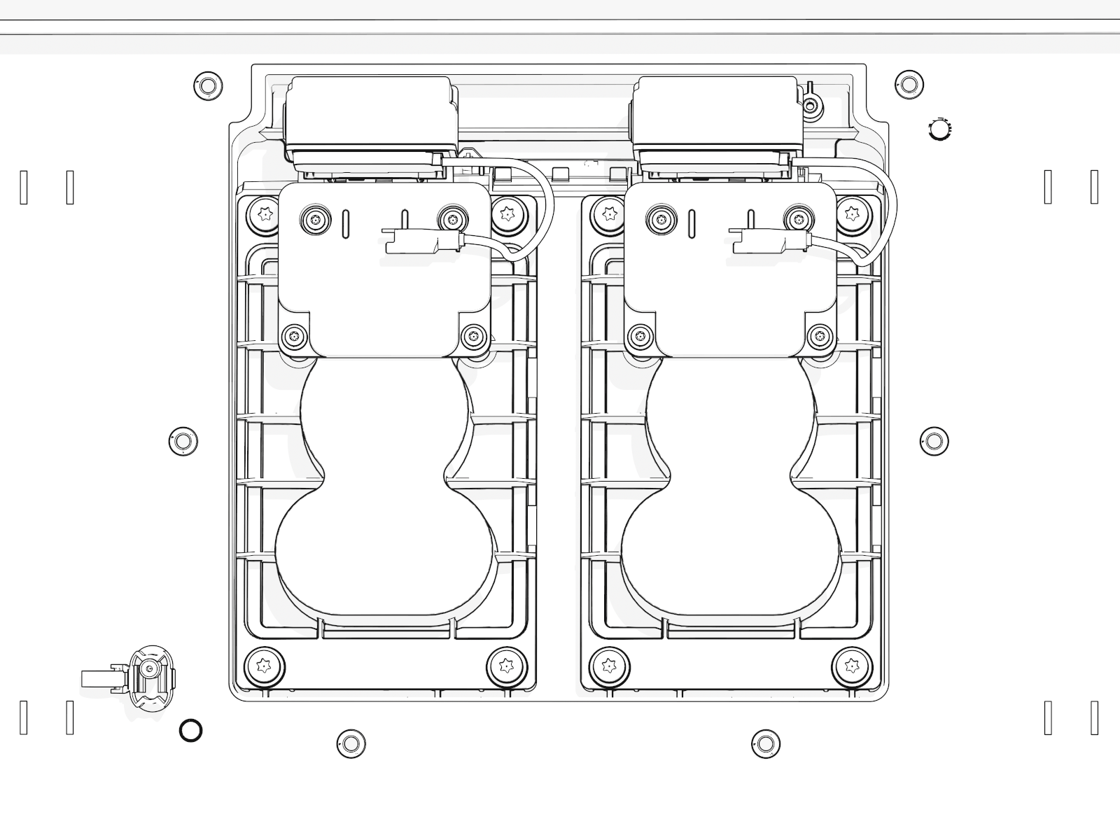
Install and Connect Holsters
-
Match each holster to the connector type for each charging cable on each side.
-
Fit the correct holster into the opening at the center. Install screws into each holster.
-
Optional lock feature:
Route and connect the wiring to each holster.
-
Route the wiring harness through the notch (at right) in the lower safety panel.
-
Locate the markings "1" and "2" on the housing at the base of the wires.
-
Connect the holster near the door hinge to wire "2".
-
Connect the holster near the door opening to wire "1".
-
Install Lower Door
-
Disengage wind stops and close the door.
-
Torque screws on the door to 4.5 Nm (40 in-lb).
-
On the right side of the door, insert the bottom of the door bracket. Tilt in the top of the door bracket. Push down into position.
-
Torque screws on the door bracket to 1 Nm (10 in-lb).
Install Covers
Follow the instructions to install covers for different variants:
(Standard Pedestal)
Identify if you have preassembled covers or unassembled components (vinyl signs, trims, and top cap).
Continue to the applicable instructions below:
A. Install Preassembled Covers
-
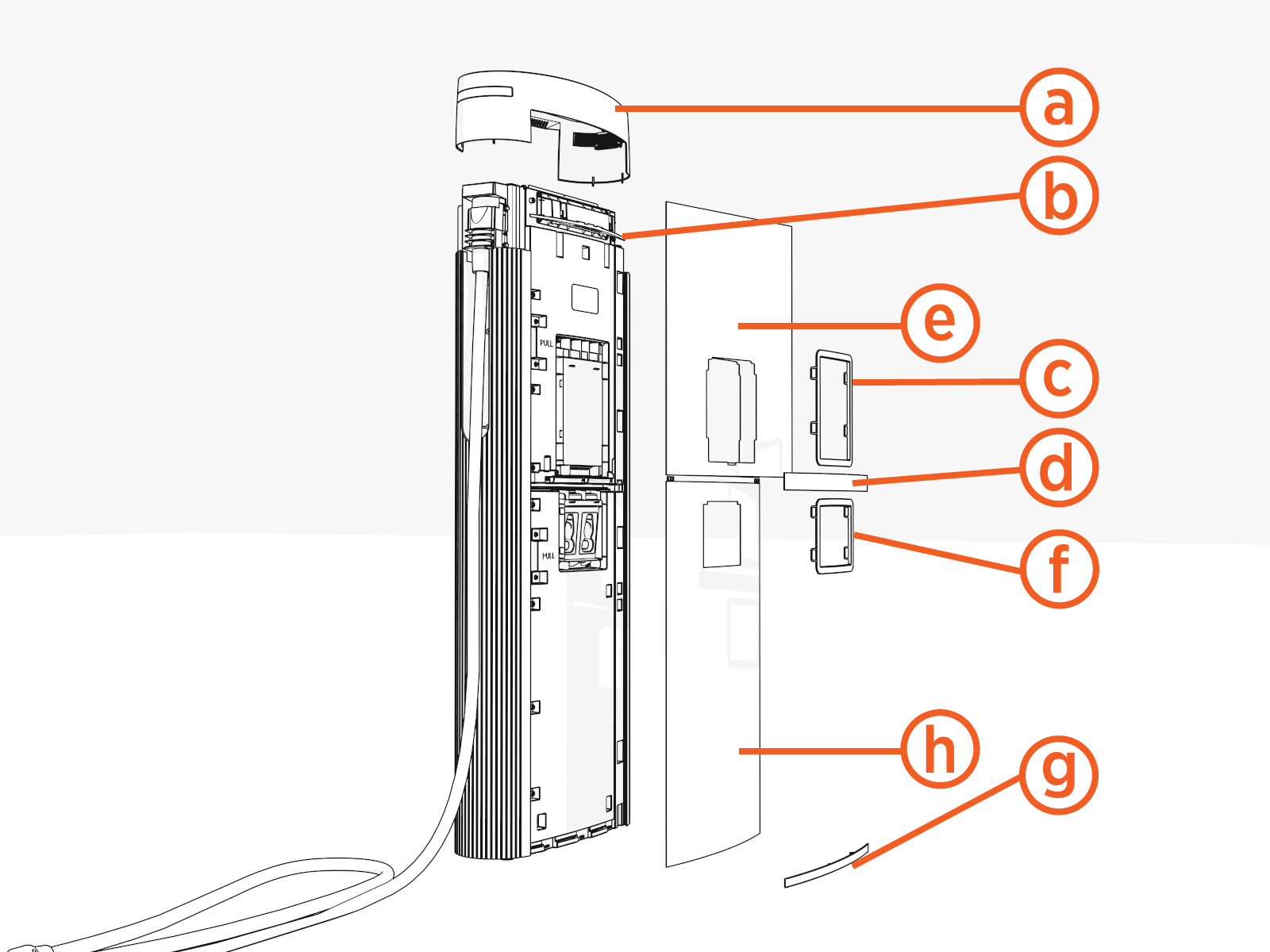
Notice the three brackets on the doors. Pins and hooks on the covers fit into these.
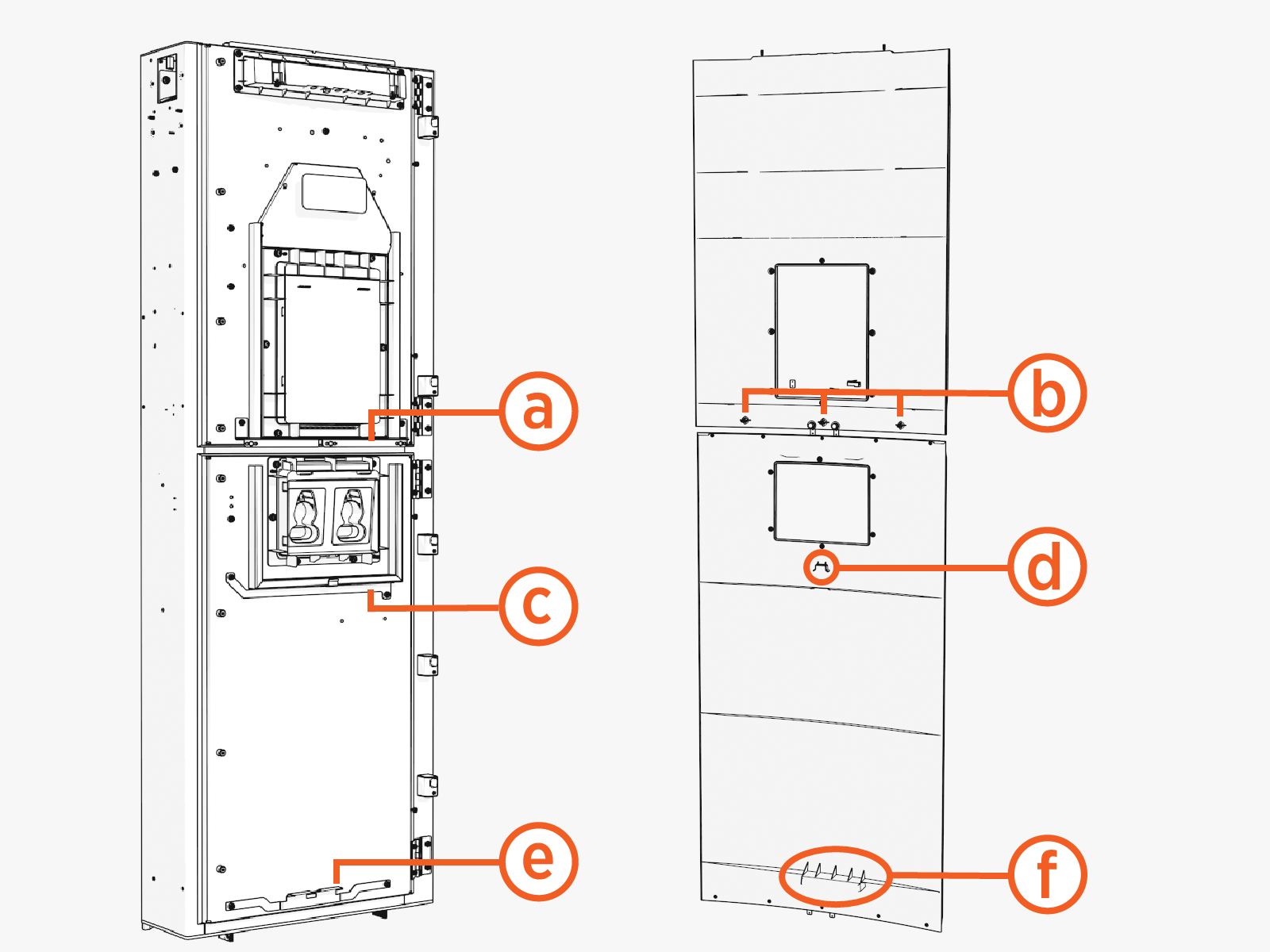
Upper door and cover:
(a) Upper bracket with three clips
(b) Three pins
Lower door and cover:
(c) Middle bracket
(d) Middle hook
(e) Lower bracket
(f) Lower hook
Front Covers
| Left Groove |
Right Groove |
|
|
|
Upper Cover
-
Slide the left or right edge of the cover into the left or right groove.
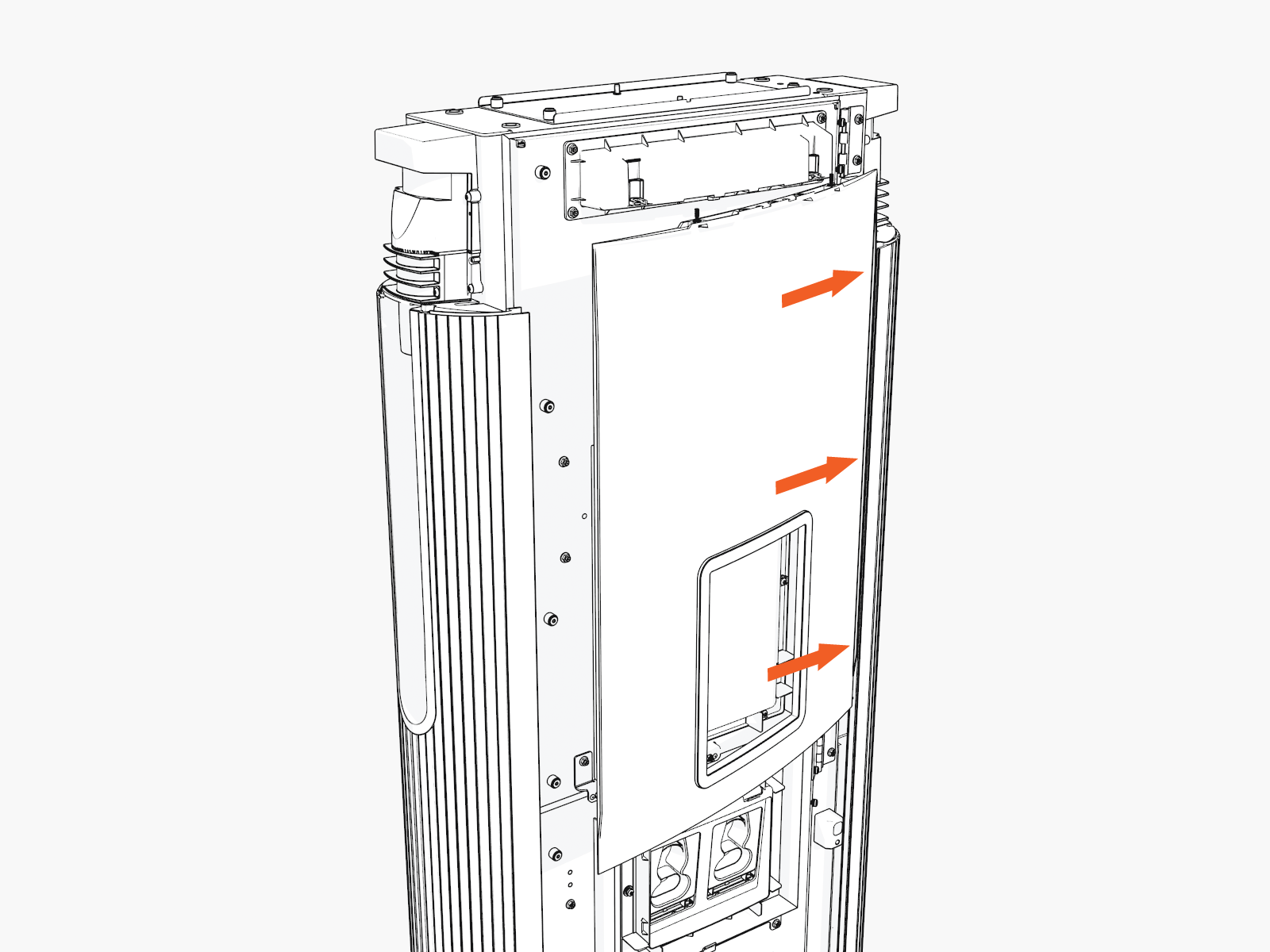
-
Rotate and bend in to slide the other edge into the other vertical groove.
While rotating in, ensure the captive screws at the top edge of the cover do not come in contact with the downlight housing.
-
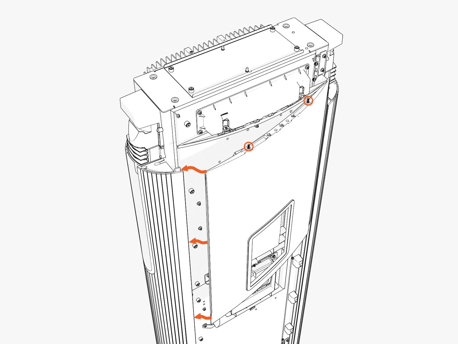
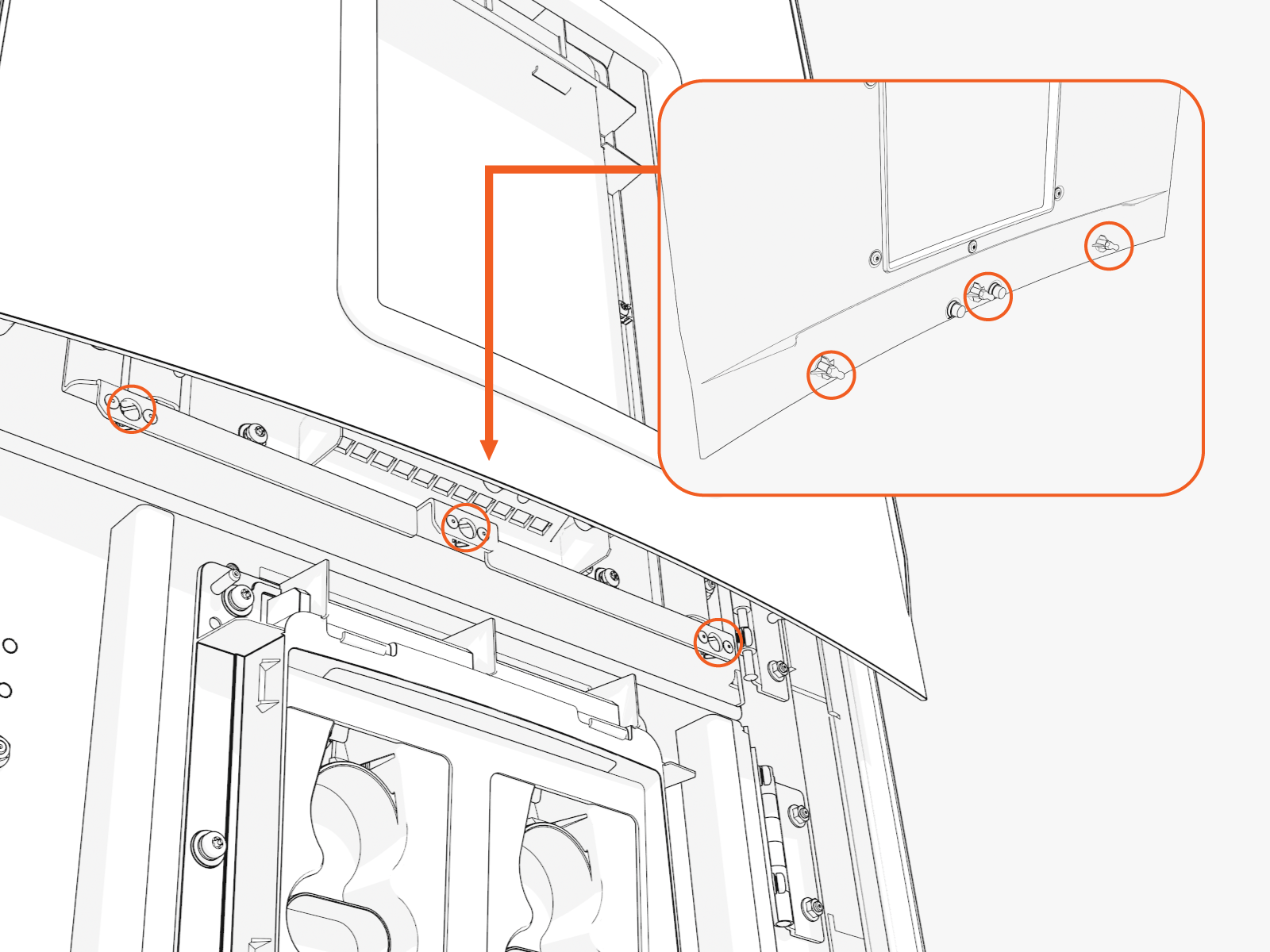
Hold and flex the bottom center of the cover slightly outward and slide it up to mate with the downlight housing. Align and seat the captive screws with the openings in the downlight housing (screws will be tightened later when the top cap is installed).
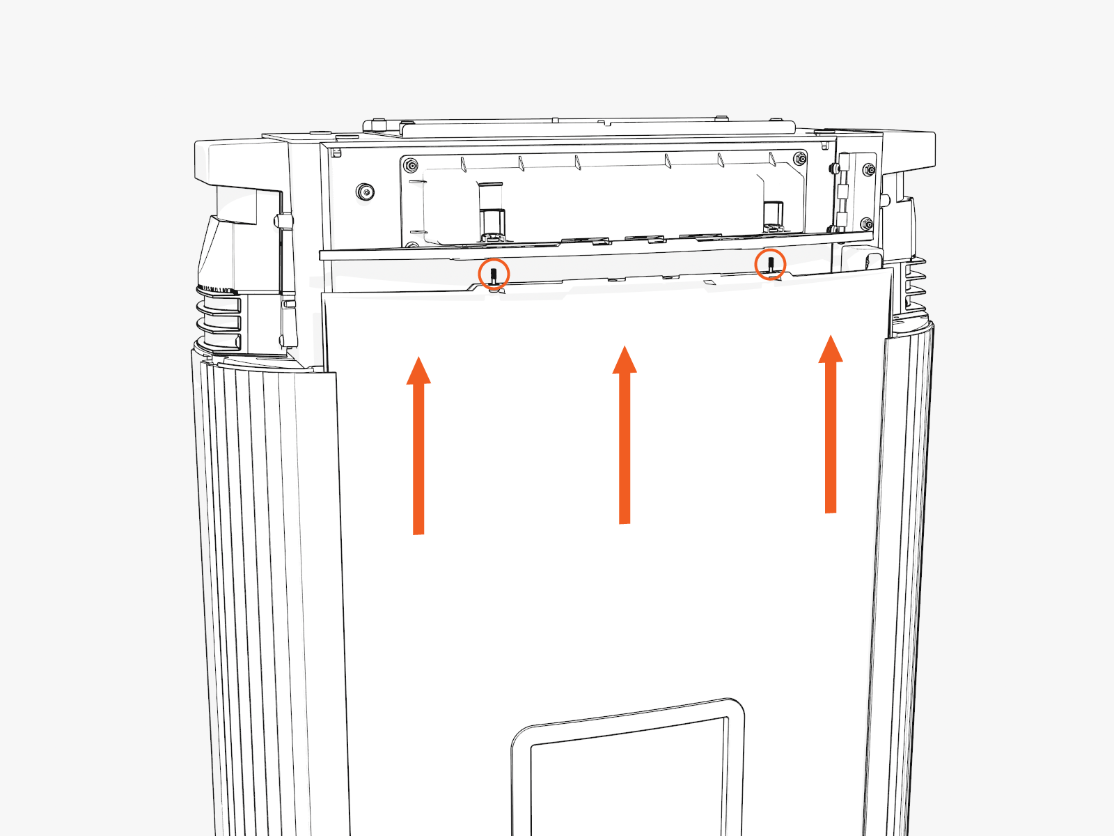
While flexed, align the three ball studs on the cover with holes into the bracket on the door, and press the cover in to clip in the ball studs.
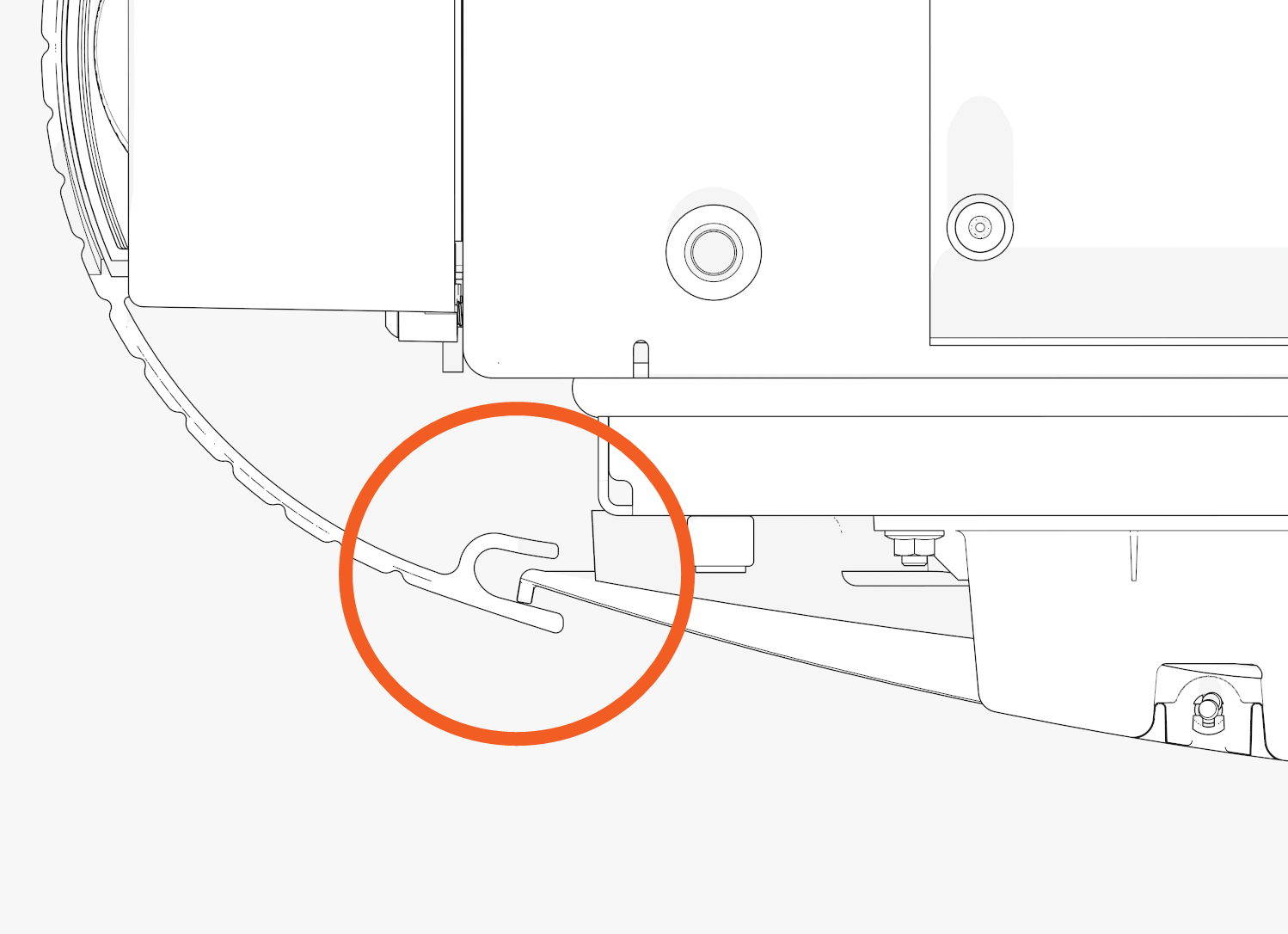
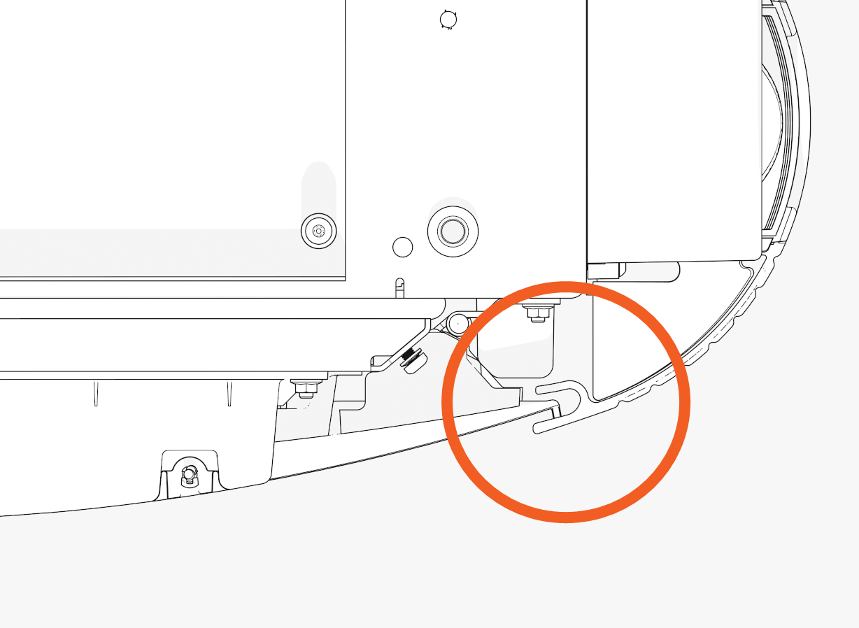
Lower Cover
-
Slide the left or right edge of the cover into the left or right groove and then rotate and bend in to slide the other edge into the other vertical groove.
While sliding in the edges, hold the top edge of the lower cover just below the lower edge of the CCOM
Control and Communications Module trim, or overlap the top portion of the lower cover about 30-35 mm (1.25-1.5 in) over the bottom portion of the upper cover.
-
Check the top and bottom corners to make sure the edges are seated in the groove, and then slide the cover down. While sliding down, press in on the lower edge of the holster trim and lower edge of the cover to engage the hooks behind the cover.
Top Cap
-
Align the screws (x4) (two at front and two at rear) and install the top cap.
Front

Rear

-
Torque the M5 screws (x2) at rear side to 2.8 Nm (25 in-lb) and M4 screws (x2) at front side to 1.7 Nm (15 in-lb) (use T25 security screwdriver).
B. Install Vinyl Signs, Trims, and Top Cover
-
Top cover (helmet)
-
Upper trim
-
Interactive display trim (optional)
-
Middle trim
-
Upper vinyl sign
-
Holster trim
-
Lower trim
-
Lower vinyl sign
-
Identify the lower trim piece and study the orientation mark..
Notice the imprint on the trim shows which edge goes "UP."
-
Push in the lower trim until it engages with the center and side clips.

-
Insert the lower cover behind the lower trim. Simultaneously insert both sides of the lower cover.

-
Hook the upper side of the holster trim onto two hooks and rotate in. Then, press the lower side of the trim into place.

-
Insert the upper cover into each side.
Logo is on upper left.
-
Align the upper cover and the ends of the middle trim. Hold the cover in position so that it does not block the trim clips.

-
Push in the middle trim until it engages with the center and side clips.

-
Align the upper trim with the magnetic side up. Insert the upper trim until it snaps into position.

-
Hook the upper side of the CCOM
Control and Communications Module trim onto two hooks and rotate in. Then press the lower side of the trim into place.
-
Align the screws (x4) (two at front and two at rear) and install the top cap.
Front
Rear
-
Torque the M5 screws (x2) at rear side to 2.8 Nm (25 in-lb) and M4 screws (x2) at front side to 1.7 Nm (15 in-lb) (use T25 security screwdriver).
Continue to Charging Cable Instructions
Check your site plans to identify your charging cable management system. Follow the applicable instructions below:
