Mount Power Link 2000
Parts Needed
To prepare for Power Link 2000 mount, find the following parts:
Prepare Power Link 2000 Site
-
Identify the Power Link 2000 mounting location per the site plan.
-
Use the mounting bracket as a template to determine placement. Measure position and ensure level
placement. Mark the locations of the mounting holes or studs.
-
Prepare the mounting holes or studs. Consult the site plan for any site-specific requirements.
Lift Power Link 2000
-
At the top of the Power Link 2000, locate four preinstalled eye bolts and lifting straps.

-
Lift up the Power Link 2000 by the lifting straps to eye level.
Use a forklift or service cart with retaining straps.

Open Power Link 2000
-
Quarter turn the door latches (x2) to unlock the door.
 to unlock the door.")
-
Open the door and engage the door stopper.

-
Slide the internal bus bar safety cover up to remove from hooks (x2) and latches (x2).
 and latches (x2).")
Remove Side Covers
-
Loosen captive screws (x2) on the interior right wall of enclosure.
 on the interior right wall of enclosure.")
-
Slide the right side panel upward to release it from the Power Link 2000 frame. Remove the panel.

-
Loosen (do not remove) nuts (x6) at the right external bus bar safety cover.
 nuts (x6) at the right external bus bar safety cover.")
-
Slide the safety cover downward to release it from the Power Link 2000 frame. Remove the cover.

-
If working with a dual-output Power Link 2000, repeat steps above to remove the left side extrusion and safety cover. Skip this step if working with a single-output Power Link 2000.

Prepare Gland Plate
-
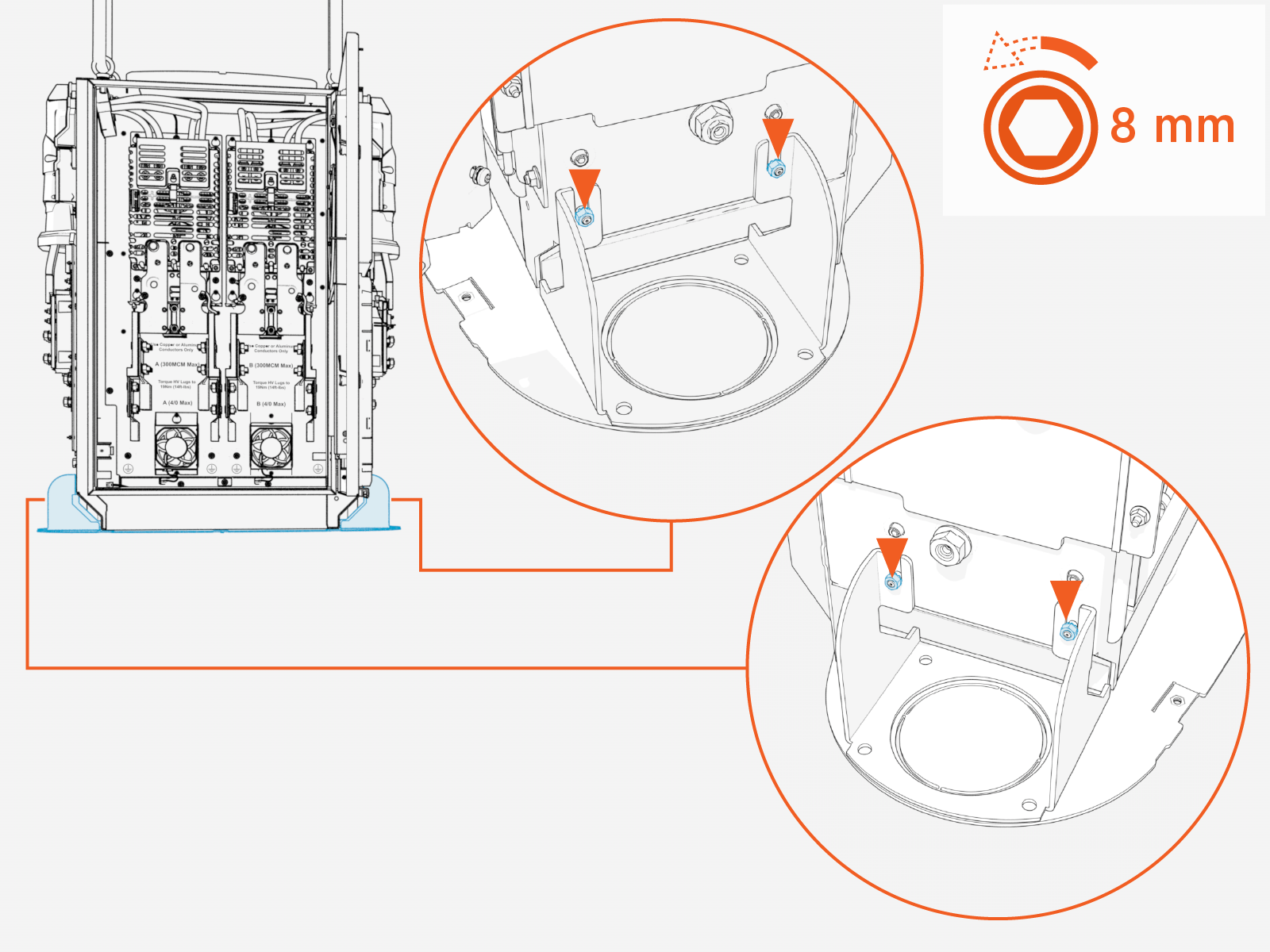
Loosen (do not remove) the nuts securing the bottom gland plate at the left and right sides of the Power Link 2000 (x2 nuts each side).
-
Remove the screws (x6) from the Power Link 2000 bottom gland plate. Save screws for later reinstall.
 from the bottom gland plate. Save screws for later reinstall.")
-
Remove the gland plate.

-
Consult the site plan to determine if the Power Link 2000 requires one or two HV DC
 High Voltage Direct Current output conduits for HV DC High Voltage Direct Current wires connecting to pantograph(s). Remove the conduit knockouts accordingly.
For single output Power Link 2000, remove only the right-side knockout.
. Remove the conduit knockouts accordingly")
-
Consult the site plan to identify the remaining HV DC
High Voltage Direct Current and LV DC Low Voltage Direct Current conduits required for the Power Link 2000. Use a hydraulic hole punch to create the needed conduit openings.-
There is limited space within the Power Link 2000 for bending HV DC
High Voltage Direct Current wires. HV DC High Voltage Direct Current conduit holes must be punched at a location that aligns wire entry with their intended power path landings. See Wiring Overview for more information. - Illustrations in this guide depict a sample conduit configuration. Actual conduit quantity, size, and position at the gland plate will vary by site.

-
-
Reinstall the gland plate with the bottom screws (x6). Torque the screws (x6) to 4.5 Nm (40 in-lb).
 to 4.5 Nm (40 in-lb).")
-
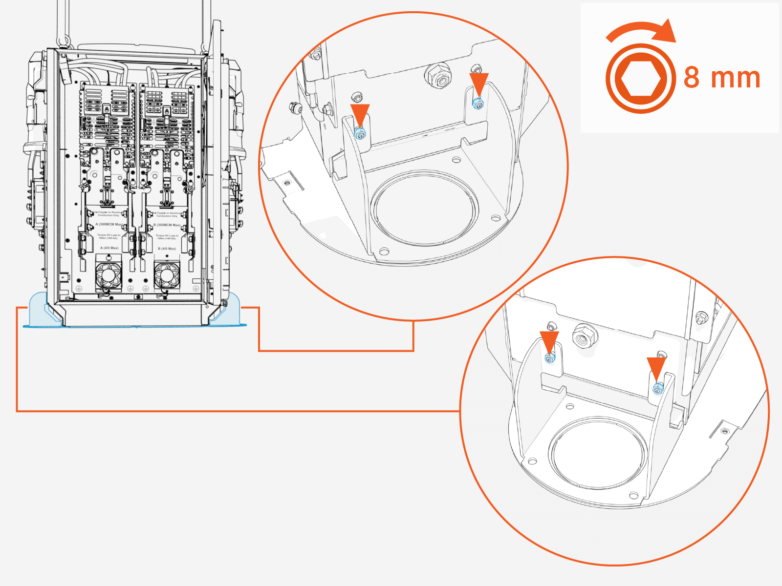
Reinstall nuts to secure the gland plate to the left and right sides of the Power Link 2000 (x2 nuts each side). Torque to 4.5 Nm (40 in-lb).
-
Disengage the door stopper and close the Power Link 2000 door.
Mount Power Link 2000
-
Attach the mounting bracket to the back of the Power Link 2000 with M6 screws (x8). Torque to 5.6 Nm (50 in-lb).
After attaching the bracket, double-check the fasteners to ensure they are torqued to the correct value.. Torque to 5.6 Nm (50 in-lb).")
-
If installing Power Link 2000 in a space where the overhead clearance does not meet the minimum requirement (305 mm or 12 in from top of product), install forklift brackets. Contact ChargePoint for details.
-
Mount the Power Link 2000 with fasteners (x6). Use fasteners specified by the site plan. Torque to the specification indicated by the site plan.
Contractor provides the fasteners. Site plans must specify fasteners appropriate for the mounting surface and rated to secure the weight of the product. After mounting the enclosure, double-check the fasteners to ensure they are torqued to the correct value.. Use fasteners specified by the site plan. Torque to the specification indicated by the site plan.")
-
Release the lifting straps and remove the eye bolts (x4) and rubber washers (x4). Use either an adjustable wrench or screwdriver's shaft to loosen the eye bolts.
 and rubber washers (x4). Use either an adjustable wrench or screwdriver's shaft to loosen the eye bolts.")
Connect Power Link 2000 Conduits
Connect conduits to the bottom gland plate.
-
Use suitable fittings to secure and seal conduits to the enclosure. Conduits must be sealed to maintain a Pollution Degree 2 environment.
-
Illustrations in this guide depict a sample conduit configuration at the bottom gland plate. Actual conduit quantity, size, and position at the gland plate will vary by site.

Save Parts
Safely set aside the side covers, external bus bar safety covers, and internal bus bar safety cover. These parts will be reinstalled when completing the Pantograph Down 2000 system install.
