Complete the Install
Complete Schunk SLS 201.102 Auxiliary Components Frame
Parts Needed
The following parts are needed from auxiliary components mounting frame install:
-
Rear cover
-
Side covers
Install Rear Cover
-
Loosen (do not remove) M6 nuts (x6) on the rear cover.
 M6 nuts (x6) on the rear cover.")
-
Install the rear cover onto the left and right rails. Slide the cover until it locks into the keyholes.

-
Tighten the M6 nuts (x6). Torque to 5.6 Nm (50 in-lb).
. Torque to 5.6 Nm (50 in-lb).")
Install Side Covers
-
Loosen (do not remove) the M6 nuts (x4) on the length of the left side cover.
 the M6 nuts (x4) on the length of the left side cover.")
-
Loosen (do not remove) M5 nuts (x4) on the side cover.
 M5 nuts (x4) on the side cover.")
-
Install the left side cover. Make sure the cover seats into slots (x6).
.")
-
Tighten M6 nuts (x4) to fasten the side cover. Torque to 5.6 Nm (50 in-lb).
 to fasten the side cover. Torque to 5.6 Nm (50 in-lb).")
-
Tighten M5 nuts at each end of the side cover (x1 nut per end). Torque to 4.5 Nm (40 in-lb).
. Torque to 4.5 Nm (40 in-lb).")
-
Repeat above steps to install the right side cover. At the front and rear ends of the frame, align and fasten the left and right side cover together with nuts (x2 each end).
.")
Close Power Link 2000
Parts Needed
The following parts, saved from Power Link 2000 mount, are needed:
-
External bus bar safety covers
-
Side panels
-
Internal bus bar safety cover
Reinstall External Bus Bar Safety Covers
-
Align the right external bus bar safety cover keyholes over nuts (x6).
.")
-
Slide the safety cover up. Ensure the top edge of the safety cover is inserted into the grommet groove above it.

-
Tighten nuts (x6). Torque to 1.7 Nm (15 in-lb).
. Torque to 1.7 Nm (15 in-lb).")
-
If applicable, repeat to install the left external bus bar safety cover.
.")
Reinstall Side Panels
-
Align the right side panel to the hooks (x2) and alignment pins (x2) on the Power Link 2000 frame.
 and alignment pins (x2) on the Power Link 2000 frame.")
-
Firmly slide the side panel downward until it engages with the hooks (x2) on the frame.
 on the frame.")
-
Fasten the side panel to the frame with captive screws on interior left wall of enclosure. Torque to 4.5 Nm (40 in-lb).
.")
-
Repeat to install the left side panel (as needed).
.")
Reinstall Internal Bus Bar Safety Cover
-
Vacuum any residue from the bottom of the enclosure.
-
Install internal bus bar safety cover onto the hooks (x2) and latches (x2). Slide the cover down to engage the latch.
 and latches (x2).")
Record MAC Address
Take a photograph of the Power Link 2000 activation QR![]() Quick Response code and MAC
Quick Response code and MAC![]() Message Authentication Code address, which can be found on the label affixed to the top of the Control and Communications Module (CCOM
Message Authentication Code address, which can be found on the label affixed to the top of the Control and Communications Module (CCOM![]() Control and Communications Module). This information is used at Power Link 2000 setup.
Control and Communications Module). This information is used at Power Link 2000 setup.
.")
Close and Lock Door
-
Disengage the windstop and close the door.

-
Quarter turn the door latches (x2).
.")
Install Power Link 2000 Covers
Parts Needed
The following parts from the Power Link 2000 package are needed:
-
Front cover
-
Bottom crown
-
Top cap
Install Power Link 2000 Front Cover
-
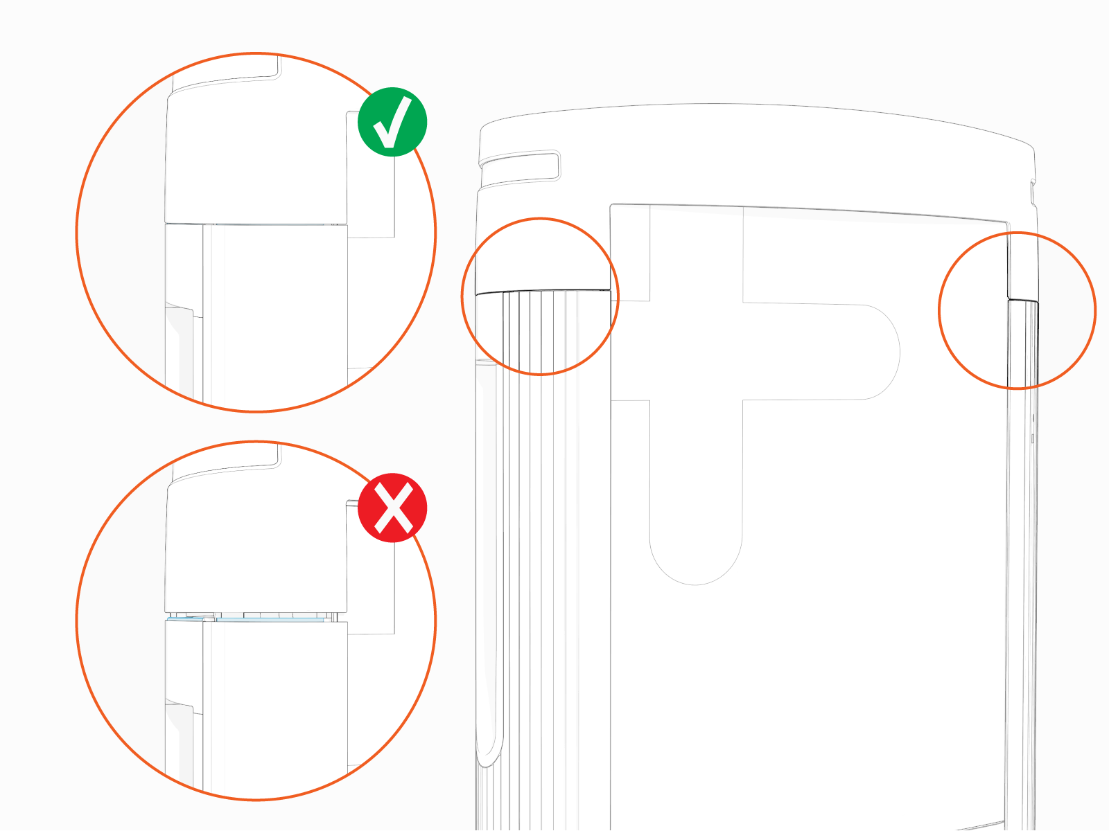
Insert any one side of the cover into the groove on the side cover.

-
Gently flex the cover to insert its other side into the groove on the other side panel. At the same time, align and hook the ball studs (x3) behind the cover into the holes (x3) in a bracket on the upper door.
 behind the cover into the holes (x3) in a bracket on the upper door.")
-
Alternatively, you can hold and flex lower side of the cover slightly outward. While flexed, align the ball studs (x3) behind the cover with the holes (x3) in the bracket on the upper door and press in.
 behind the cover with the holes (x3) in the bracket on the upper door and press in.")
-
Make sure that the screws (x2) on the front upper cover are seated in their slots in the area light housing.
 on the front upper cover are seating in their slots in the area light housing.")
Install Power Link 2000 Bottom Crown
Install the bottom crown. Torque captive screws (x3) to 4.5 Nm (40 in-lb).
 to 4.5 Nm (40 in-lb).")
Install Power Link 2000 Top Cap
-
Align the screws (x4) and install the top cap.
-
Front screws (x2)
 and install the top cap.")
-
Rear screws (x2)
 and install the top cap.")
-
-
Make sure that the top cap sides are seated on edges on top of the side panels (x2).
-
Torque the rear screws (x2) to 2.8 Nm (25 in-lb) and front screws (x2) to 1.7 Nm (15 in-lb).
 to 2.8 Nm (25 in-lb) and front screws (x2) to 1.7 Nm (15 in-lb).")
Adjust Power Link 2000 Ratings Label
Power Link 2000 units ship from the factory with a 500 A output current ratings label. If the installed Power Link 2000 is configured for an output rating of value other than 500 A, an adjustment ratings label must be applied.
Parts Needed
The following part is needed, from the Power Link 2000 package:
-
Ratings adjustment label sticker sheet
Check and Adjust Label
-
Verify the Power Link 2000 output rating per the site plan. If the rating is 500 A, skip this section. Otherwise proceed through the next steps.
-
Locate the ratings label on the rear of the Power Link 2000.

-
Choose the appropriate ratings adjustment label from the label sticker sheet.
-
Adhere the ratings adjustment label over the existing ratings label.

Close and Lock PD Controller
-
Vacuum any residue from the bottom of the enclosure.
-
Close the door.

-
Quarter turn to lock the door.

