Connect PD Controller Wires
Wiring Overview
The PD Controller is configured with the following wire connections:
-
120-277 V AC input from the site
-
LV DC
 Low Voltage Direct Current input, chassis ground, and Ethernet connection from a Power Link 2000
 -
RF coaxial connection to a Wi-Fi
Wireless Fidelity Antenna -
RF coaxial connection to an RFID
Radio Frequency IDentification Antenna
For AC and LV DC![]() Low Voltage Direct Current input wire quantities, sizes, and terminations, see Wires and Terminations Required for Site.
Low Voltage Direct Current input wire quantities, sizes, and terminations, see Wires and Terminations Required for Site.
Wire landing locations within the PD Controller are shown below.

-
120-277 V AC input
-
AC PE
-
Ethernet input
-
Controller interface cable
-
Chassis ground
-
Wi-Fi
Wireless Fidelity antenna
Parts Needed
To prepare for wiring, find the wire terminal operating tool (shipped in the Auxiliary Components Kit).

Connect AC Input Wires
-
Open the PD Controller enclosure.

-
Pull and cut the 120-277 V AC wires to length for landing on the AC circuit breaker and ground terminal.
The AC wire length inside the enclosure must not exceed 127 mm (5 in). Allowing a longer wire length inside the enclosure leaves a potential for protection circuitry failure and introduces a potential electrical hazard.
-
Strip the AC wire jackets.

-
Loosen the AC circuit breaker set screws (x2).
.")
-
Insert the AC wires into the terminals. Insert the live wire into the upper terminal. Insert the neutral wire into the lower terminal.

-
Torque the AC circuit breaker set screws (x2) to 2.4 Nm (21.2 in-lb) for 18-12 AWG
American Wire Gauge wires, 2.8 Nm (24.8 in-lb) for 10-8 AWG American Wire Gauge wires, or 4 Nm (35.4 in-lb) for 6 AWG American Wire Gauge wires. Push-pull to test the wires are secured..")
-
Flip the AC circuit breaker switches (x2) to the ON position. The indicator window should display red.
 to the ON position. The indicator window should display red.")
-
Strip the AC PE wire jacket.

-
Loosen the AC PE terminal set screw.

-
Insert the AC PE wire into the terminal.

-
Torque the terminal set screw to 1.7 Nm (15 in-lb). Push-pull to test the wire is secure.
. Push-pull to test the wire is secure.")
Connect LV DC and Ethernet Wires
Pull Wires
If not already done, pull the 48 V DC wires, Ethernet cable, and chassis ground wire into the enclosure. These wires connect from the Power Link 2000.

Cut and Connect 48 V DC and Ground Chassis Wires
Wire Landing Locations
Study the table and diagram below to identify wire landing locations. Also note the wire strip length given.
| Wire | Terminal Block ID | Port Number | Wire Strip Length |
|---|---|---|---|
|
48 V DC positive (+) |
TB14 |
1A |
10 mm (0.4 in) |
|
48 V DC negative (-) |
TB14 |
2A |
|
|
Chassis ground |
TB2 |
3 |
12 mm (0.5 in) |

Connect Wires
Follow the procedure below to connect each 48 V DC and chassis ground wire:
-
Route and cut the wire to length for landing on its designated terminal.
-
Strip the wire end.
-
Insert the wire into its designated terminal port.
-
For TB14, use the wire terminal operating tool to facilitate wire insertion.
Before inserting a wire into the terminal, the operating tool must be fully inserted to release the latch mechanism. Otherwise the terminal block may be damaged. -
For TB2, use a 3.5 mm or smaller flathead screwdriver to release the port clamp for wire insertion.
-
-
Push-pull to test the wire is secure.
Connect Ethernet Cable
-
Route the Ethernet (Cat6 STP
Shielded Twisted Pair) cable to the Ethernet surge suppressor and trim to length. Allow for a service loop. cable to the Ethernet surge suppressor and trim to length. Allow for a service loop.")
-
Field crimp a shielded RJ45 connector onto the Ethernet cable. Use straight-through T568B pattern.
Do not ground the shield at this end of the cable. Ground the shield at the end of the cable that connects to the Power Link 2000.
-
Test the Ethernet cable for functionality.

-
Connect the cable to the Ethernet surge suppressor.
To establish a secure connection, the RJ45 connector latch must click into the surge suppressor port.

Connect Antenna Cables
-
Route the Wi-Fi
Wireless Fidelity and RFID Radio Frequency IDentification antenna cables into the PD Controller enclosure.-
For cables run without conduit:
Route the cables into the PD Controller through the 3/4 in NPT
National Pipe Thread cable gland.Feeding the RP-SMA connectors through the cable gland may require care due to a snug fit. See Appendix: RFID and Wi-Fi Antenna Cable Reference for recommended technique.

-
For cables specified to run with conduit:
Pull the cables through the conduit into the PD Controller (if not already done).
If the 3/4 in NPT
National Pipe Thread cable gland (provided with PD Controller) is used to seal the end of the conduit nearest to the pantograph, feeding the RP-SMA connectors through the cable gland may be snug. See Appendix: RFID and Wi-Fi Antenna Cable Reference for recommended technique.
The cables can be pulled through the conduit in only one direction, from the antennas to the PD Controller.
-
For cables run with or without conduit:
Coil the cables outside the enclosure as needed to take up excess slack.
-
Do not coil the antenna cables within the PD Controller.
-
If the cables are already connected at the antennas, you may need to disconnect the cables from the antennas to take up excess cable slack at the antennas and then reconnect the cables. See Connect Auxiliary Component Cables.
The LMR-240 antenna cables shipped with product have a one-time bend radius of 19 mm (0.75 in) and repeated bend radius of 63 mm (2.5 in). Do not exceed the bend radius or the cable may be damaged and the system may not operate. If using an LMR-240 equivalent cable, do not exceed the bend radius limits for the cable type used. -
-
-
Connect the Wi-Fi
Wireless Fidelity cable to the Wi-Fi Wireless Fidelity Access Point. Rotate the right-angle adapter as needed to facilitate the connection. Torque to 0.45 Nm (4 in-lb).
-
Connect RFID
Radio Frequency IDentification cable to the RFID Radio Frequency IDentification Reader. Rotate the right-angle adapter as needed to facilitate the connection. Torque to 0.45 Nm (4 in-lb).
-
Torque the right-angle adapters to 0.45 Nm (4 in-lb).
-
Seal the wire entry.
-
For cables run without conduit:
The cable gland is located at the PD Controller. Torque the cap to 4.5 Nm (40 in-lb). Torqe the nut to 7.9 Nm (70 in-lb).

-
For cables run with conduit:
If the 3/4 in NPT
National Pipe Thread cable gland was relocated to the end of the conduit near the antennas, torque the cable gland cap to 4.5 Nm (40 in-lb). Use a 33 mm wrench. Otherwise apply duct seal compound to seal the conduit end.
-
-
If the antenna cables are not run through conduit, use zip ties to secure and support the cables along the full length of the cables outside of the PD Controller.
Connect Controller Interface Cable Wires
Prepare for Wire Connection
-
Familiarize yourself with the controller interface cable wires that terminate at the PD Controller. See Controller Interface Cable Schunk SLS 201.102.
-
Route the controller interface cable into the PD Controller enclosure.
-
For cable run without conduit:
Route the cable to enter the PD Controller through the 1-1/4 in NPT
National Pipe Thread cable gland.
-
For cable specified to run with conduit:
Pull the cable through the conduit into the PD Controller (if not already done).
The cable can be pulled through the conduit in only one direction, from the pantograph to the PD Controller.
-
For cable run with or without conduit:
The controller interface cable may not coil or bunch within the enclosure. In the following steps, cable wires must be cut to length for routing directly to the landing terminals, without excess wire length.
-
-
Familiarize yourself with the system cables bundled within the controller interface cable. See cable cross-section provided below. For more detail see Controller Interface Cable Schunk SLS 201.102.

-
Pantograph rest sensor cable
-
Pantograph control pilot cable
-
Pantograph control cable
-
Status LED cable
-
Connect Pantograph Control Cable Wires
Wire Landing Locations
Study the table and diagram below to identify wire landing locations. Also note the wire strip length given.
| Wire | Wire Color | Wire Gauge | Terminal Block ID | Port Number | Wire Strip Length |
|---|---|---|---|---|---|
|
Pantograph low current 24 V |
Red/white |
(0.5 mm2) |
TB9 |
4 |
13 mm (0.5 in) |
|
Pantograph motor GND |
Black |
(2.5 mm2) |
TB8 |
6 |
12 mm (0.5 in) |
|
Pantograph high current GND |
Black |
(1.5 mm2) |
TB8 |
5 |
12 mm (0.5 in) |
|
Pantograph low current GND |
Black |
(0.5 mm2) |
TB8 |
4 |
12 mm (0.5 in) |
|
Pantograph high current 24 V |
Red |
(2.5 mm2) |
TB10 |
4 |
13 mm (0.5 in) |
|
Raised |
Blue |
(0.5 mm2) |
TB11 |
4B |
10 mm (0.4 in) |
|
Lowered |
Yellow |
(0.5 mm2) |
TB11 |
3B |
10 mm (0.4 in) |
|
Request raise |
Blue/white |
(0.5 mm2) |
TB13 |
4B |
10 mm (0.4 in) |
|
Request lower |
Yellow/white |
(0.5 mm2) |
TB13 |
3B |
10 mm (0.4 in) |

Each terminal ships with wires that are factory-installed on one half of the terminal. The field-installed wires shall install on the opposite half of the terminal, mirroring the factory-installed wires in terms of port position and wire color.
Connect wires
Follow the procedure below to connect each individual pantograph control cable wire:
-
Route and cut the wire to length for landing on its designated terminal.
-
Strip the wire end.
-
Install wire ferrule (option).
-
Insert the wire into its designated terminal port.
-
For TB11 and TB13, use the wire terminal operating tool to facilitate wire insertion.
Before inserting a wire or ferrule into the terminal, the operating tool must be fully inserted to release the latch mechanism. Otherwise the terminal block may be damaged. -
For TB8, TB9, and TB10, use a 3.5 mm or smaller flathead screwdriver to release the port clamp for wire insertion, or push ferrule termination into the terminal block port.
-
-
Push-pull to test the wire is secure.
Connect Pantograph Rest Sensor Cable Wires
Wire Landing Locations
Study the table and diagram below to identify wire landing locations. Also note the wire strip length given.
| Wire | Wire Color | Wire Gauge | Terminal Block ID | Port Number | Wire Strip Length |
|---|---|---|---|---|---|
|
Rest signal |
Green/blue |
(0.5 mm2) |
TB11 |
1B |
10 mm (0.4 in) |
|
Rest 24 V |
Red/white |
(0.5 mm2) |
TB9 |
3 |
13 mm (0.5 in) |
|
Rest GND |
Black |
(0.5 mm2) |
TB8 |
3 |
12 mm (0.5 in) |
Each terminal ships with wires that are factory-installed on one half of the terminal. The field-installed wires shall install on the opposite half of the terminal, mirroring the factory-installed wires in terms of port position and wire color.
Connect Wires
Follow the procedure below to connect each individual rest sensor cable wire:
-
Route and cut the wire to length for landing on its designated terminal.
-
Strip the wire end.
-
Install wire ferrule (option).
-
Insert the wire into its designated terminal port.
-
For TB11, use the wire terminal operating tool to facilitate wire insertion.
Before inserting a wire or ferrule into the terminal, the operating tool must be fully inserted to release the latch mechanism. Otherwise the terminal block may be damaged. -
For TB8 and TB9, use a 3.5 mm or smaller flathead screwdriver to release the port clamp for wire insertion, or push ferrule termination into the terminal block port.
-
-
Push-pull to test the wire is secure.
Connect Pantograph Control Pilot Cable Wires
Wire Landing Locations
Study the table and diagram below to identify wire landing locations. Also note the wire strip length given.
| Wire | Wire Color | Wire Gauge | Terminal Block ID | Port Number | Wire Strip Length |
|---|---|---|---|---|---|
|
Control pilot |
White/brown |
(0.5 mm2) |
TB5 |
1B |
12 mm (0.5 in) |
|
Control pilot shield |
Brown/black |
(0.5 mm2) |
TB5 |
2B |
12 mm (0.5 in) |

Each terminal ships with wires that are factory-installed on one half of the terminal. The field-installed wires shall install on the opposite half of the terminal, mirroring the factory-installed wires in terms of port position and wire color.
Connect Wires
Follow the procedure below to connect each individual control pilot cable wire:
-
Route and cut the wire to length for landing on its designated terminal.
-
Strip the wire end.
-
Install wire ferrule (option).
-
Insert the wire into its designated terminal port. Use a 3.5 mm or smaller flathead screwdriver to release the port clamp for wire insertion, or push ferrule termination into the terminal block port.
-
Push-pull to test the wire is secure.
Connect Status LED Cable Wires
Wire Landing Locations
Study the table and diagram below to identify wire landing locations. Also note the wire strip length given.
| Wire Color | Wire Gauge | Terminal Block ID | Port Number | Wire Strip Length |
|---|---|---|---|---|
|
Orange |
24 AWG |
TB6 |
1B |
10 mm (0.4 in) |
|
White/orange |
24 AWG |
TB6 |
2B |
10 mm (0.4 in) |
|
Brown |
24 AWG |
TB6 |
3B |
10 mm (0.4 in) |
|
White/brown |
24 AWG |
TB6 |
4B |
10 mm (0.4 in) |
|
Blue |
24 AWG |
TB7 |
1B |
10 mm (0.4 in) |
|
White/blue |
24 AWG |
TB7 |
2B |
10 mm (0.4 in) |
|
Green |
24 AWG |
TB7 |
3B |
10 mm (0.4 in) |
|
White/green |
24 AWG |
TB7 |
4B |
10 mm (0.4 in) |
Each terminal ships with wires that are factory-installed on one half of the terminal. The field-installed wires shall install on the opposite half of the terminal, mirroring the factory-installed wires in terms of port position and wire color.
Connect Wires
Follow the procedure below to connect each individual status LED cable wire:
-
Route and cut the wire to length for landing on its designated terminal.
-
Strip the wire end.
-
Install wire ferrule (option).
-
Insert the wire into its designated terminal port. Use the wire terminal operating tool to assist wire insertion.
Before inserting a wire or ferrule into the terminal, the operating tool must be fully inserted to release the latch mechanism. Otherwise the terminal block may be damaged. -
Push-pull to test the wire is secure.
Secure Controller Interface Cable
-
Seal the wire entry.
-
For cable run without conduit:
The cable gland is located at the PD Controller. Torque the cap to 4.5 Nm (40 in-lb). Torque the nut to 10.2 Nm (90 in-lb).
-
For cable run with conduit:
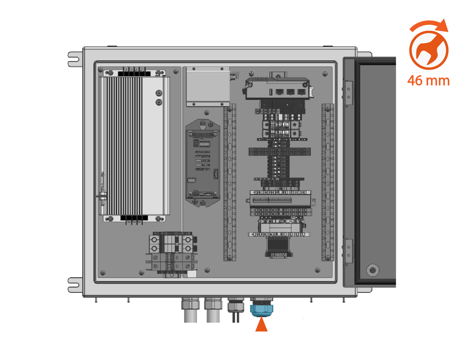
If the 3/4 in NPT
National Pipe Thread cable gland was relocated to the end of the conduit near the pantograph and status LED, torque the cap to 4.5 Nm (40 in-lb). Use a 46 mm wrench. Otherwise apply duct seal compound to seal the conduit end.
-
-
Use zip ties to secure and support the cable along its full length outside of the PD Controller. Skip this step if the cable is run through conduit.
