Connect the Head Assembly
-
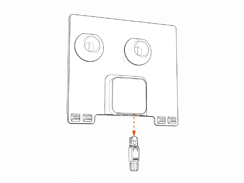
If you are setting the CP6000 charging station up to connect to a local Ethernet network, remove the RJ45 Ethernet connector from the Ethernet module in the kit. If you are not setting up Ethernet capability, skip to step 2.
-
Slide the power plate cover or Ethernet module down.

-
Remove the head assembly from the packaging by holding the metal castings.
Wear protective gloves. Hold the metal edges of the head assembly, not the plastic front cover, to avoid damaging the front cover.
-
Align the rails on the head assembly with the pedestal and slide it into the pedestal housing.
Avoid damaging cables when installing the head assembly.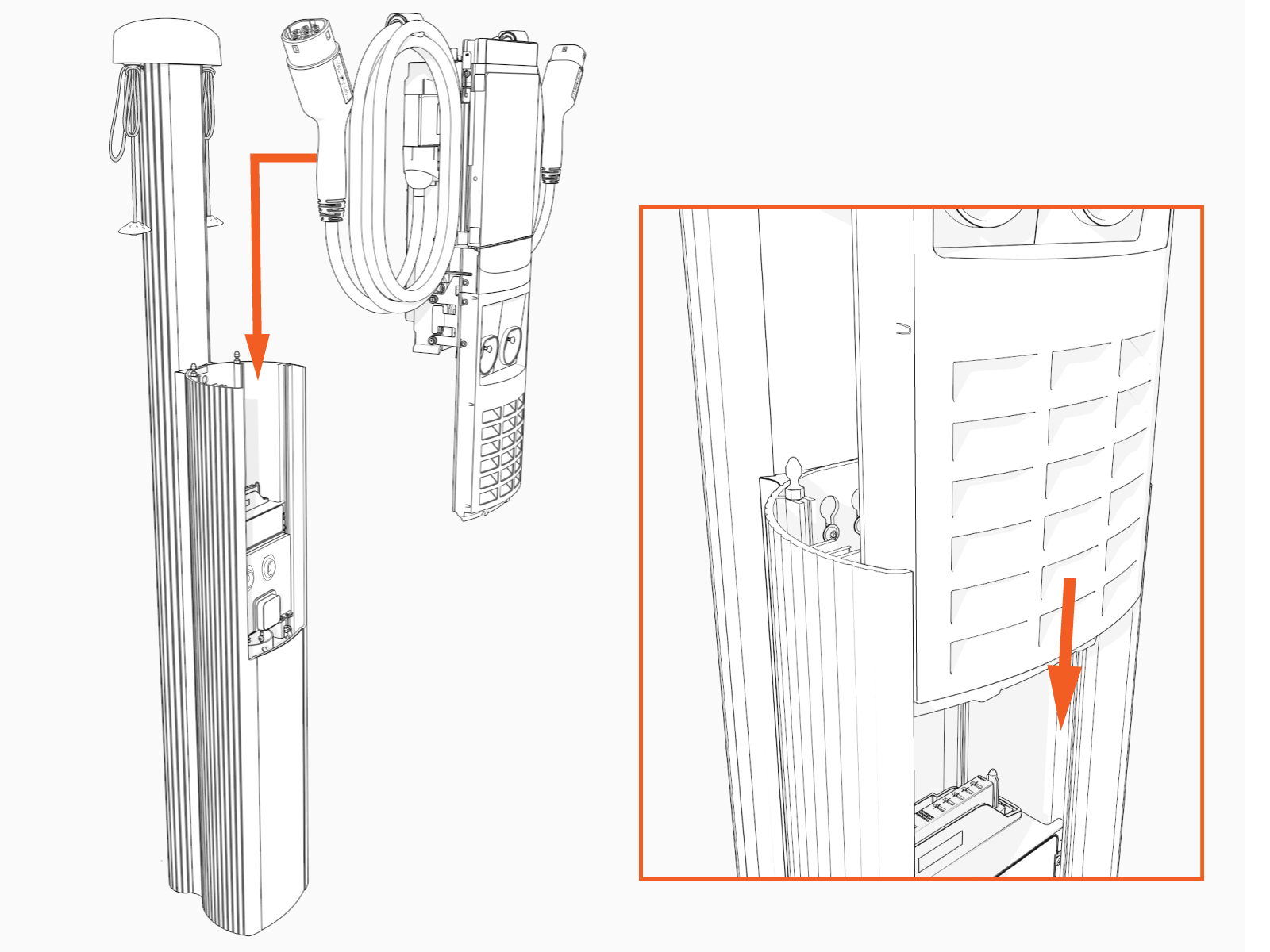
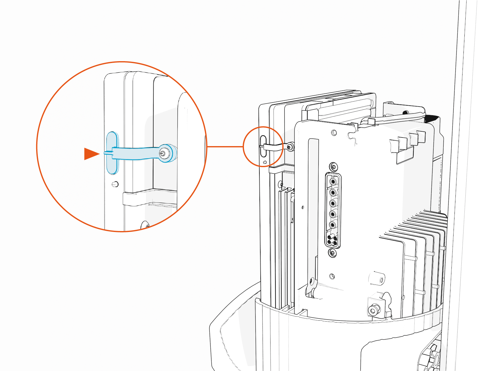
The head assembly rests on the L-wrench connected to the side of the assembly.

-
Install the SIM card.
The CP6000 includes two separate SIM cards – an embedded SIM card (a chip) and a SIM slot that supports physical SIM cards. If the physical SIM card provided with the station head unit is multi-punch or break-apart, as in the example below (a), then make sure to punch out the size matching the SIM being replaced in the unit. CP6000 stations use Mini SIM (2FF).
 Card")
Follow the instructions provided below to replace the pre-installed SIM card with the one taped to the station head unit.
-
Remove the SIM card from its carrier by pushing it firmly.
-
Remove the top cap to access the service panel (position).
-
Remove the front lens to locate the SIM plug on the head assembly.
-
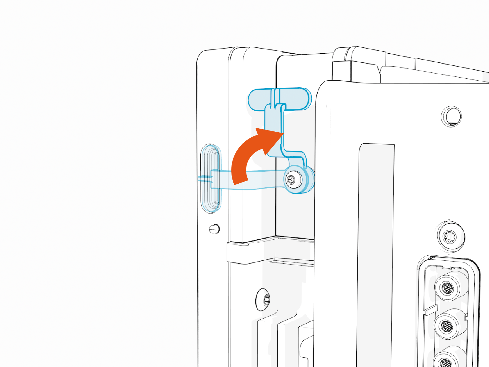
Lift the SIM plug located on the head assembly.
-
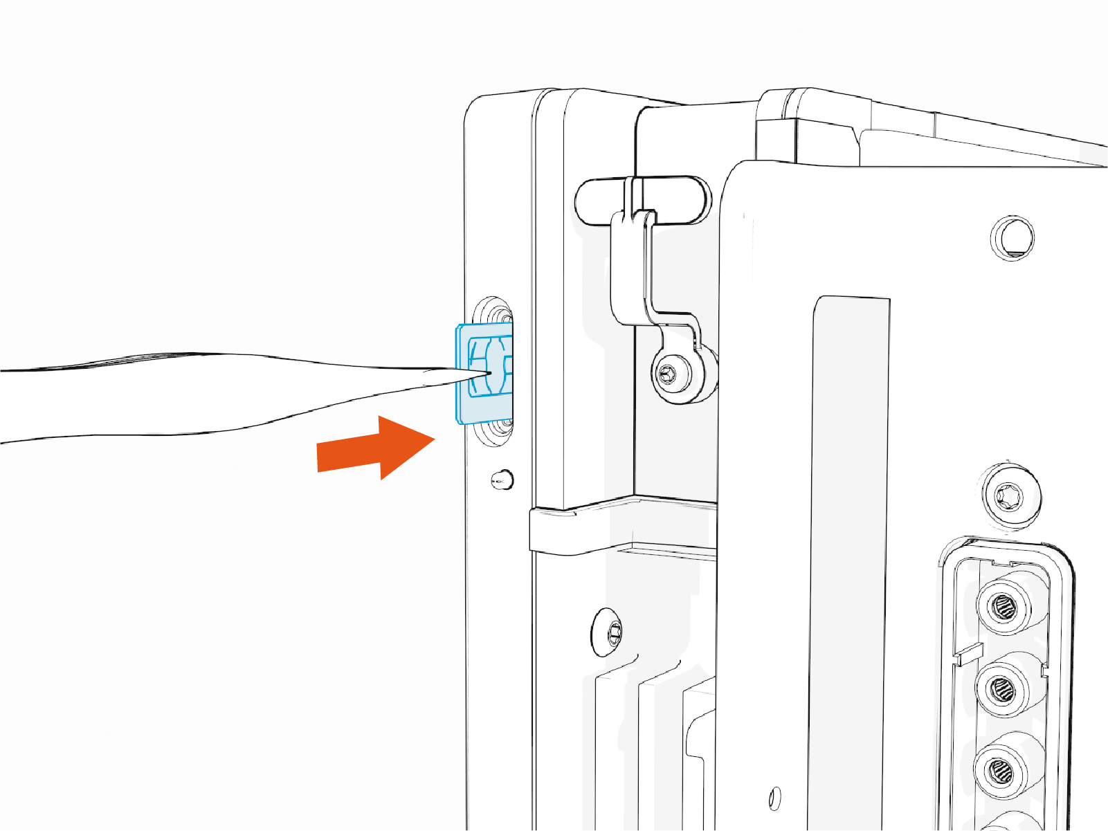
Insert the notched edge of the SIM card into the slot with the notch facing upward. Slide it into the slot and use a corner of the SIM card's carrier or a tweezer to push it fully into the slot until it clicks into place. Refer to the orientation instructions printed on the side of the head assembly.
-
-
After securing the SIM card in place, return the SIM plug to its original position and reattach the front lens.
-
If you are installing the Ethernet module, visit Install the Install the USB to Ethernet Module.
-

-
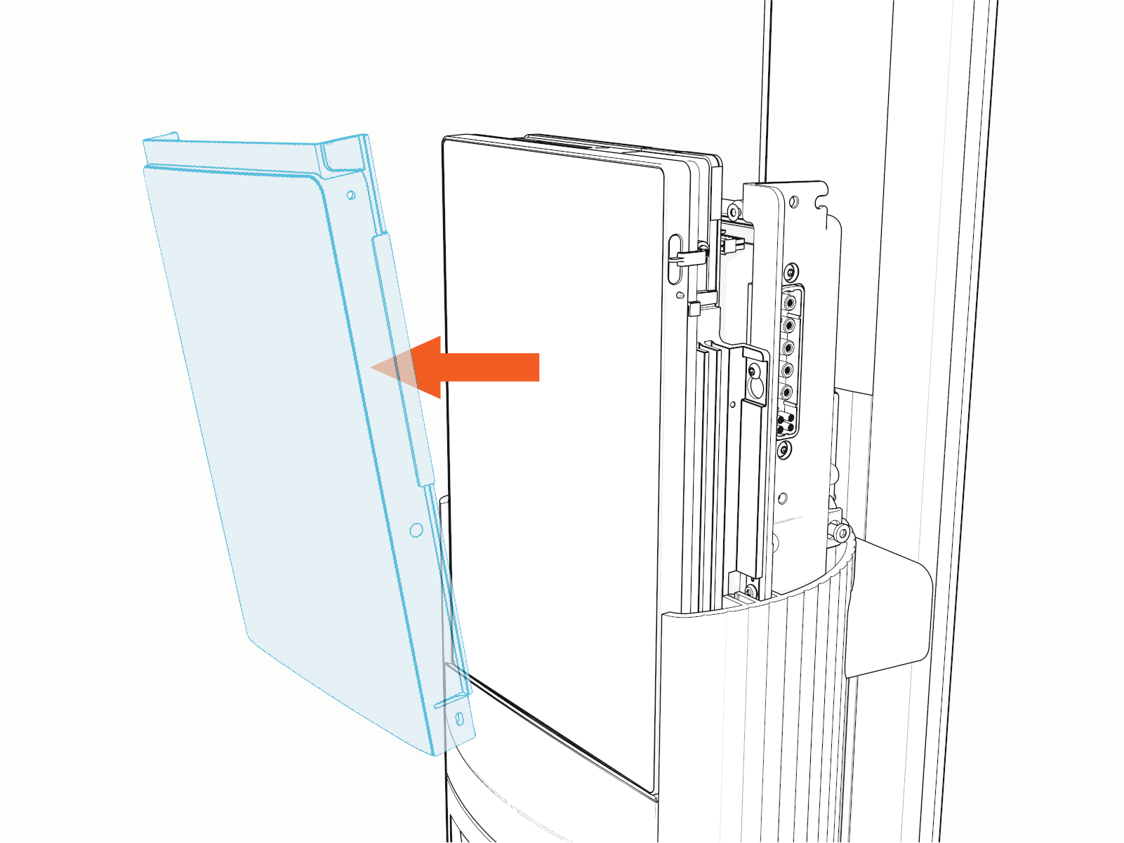
Slide the head assembly all the way into the pedestal housing. Ensure the head assembly is fully seated.
If the head assembly doesn't slide all the way into the pedestal housing, check that the power plate is seated correctly.
-
Using the L-wrench or 4 mm hex tool, tighten two screws.

-
Take a picture of the activation label, remove the protective film, and give the protective film with the label to the station owner.

-
Slide the top cap onto the head assembly, adjusting as necessary to clear the charging cables, until it fits into place.

-
Torque two captive screws to 1.1 Nm (10 in-lb).
")
