Install the Station and Charging Cable
Proceed to the following topics to install the charging station and charging cable.
Mount the Station
-
Remove the faceplate and the wire cover from the charging station. Set them aside.

-
Insert a 3/8 inch screw into the top center hole on the front of the bracket using a #2 Phillips screwdriver. Leave the screw protruding approximately 6 mm (1/4 inch) to create a 3 mm (1/8 inch) gap between the back of the screw head and the bracket.
-
Position the mounting skirt against the back of the main unit.
-
Route the service wiring through the knockout in the back or the bottom of the main unit based on the configuration.
-
Hang the mounting skirt and the main unit on the top protruding screw on the bracket.
-
Insert two hex screws (3/4 inch) through the holes near the bottom center and secure the main unit.
-
Tighten the hex screws using a 3/8 inch hex driver.
Review the Wiring Diagram
240 VAC Single Phase Panel
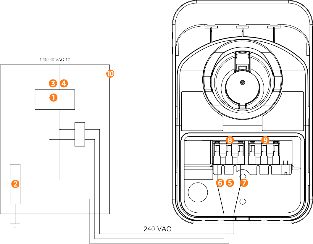
(1) Main Breaker
(2) Ground Bus
(3) L1
(4) L2
(5) Ground
(6) L1
(7) L2
(8) Input Terminal Block
(9) Output Terminal Block
(10) Local Service or Sub Panel
208 VAC Three Phase Panel
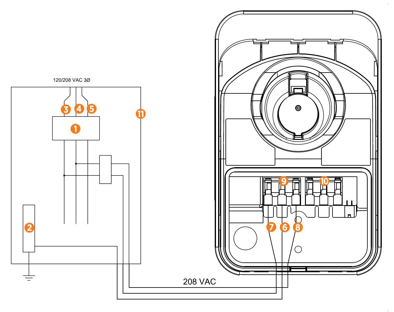
(1) Main Breaker
(2) Ground Bus
(3) L1
(4) L2
(5) L3
(6) Ground
(7) L1
(8) L2/N
(9) Input Terminal Block
(10) Output Terminal Block
(11) Local Service or Sub Panel
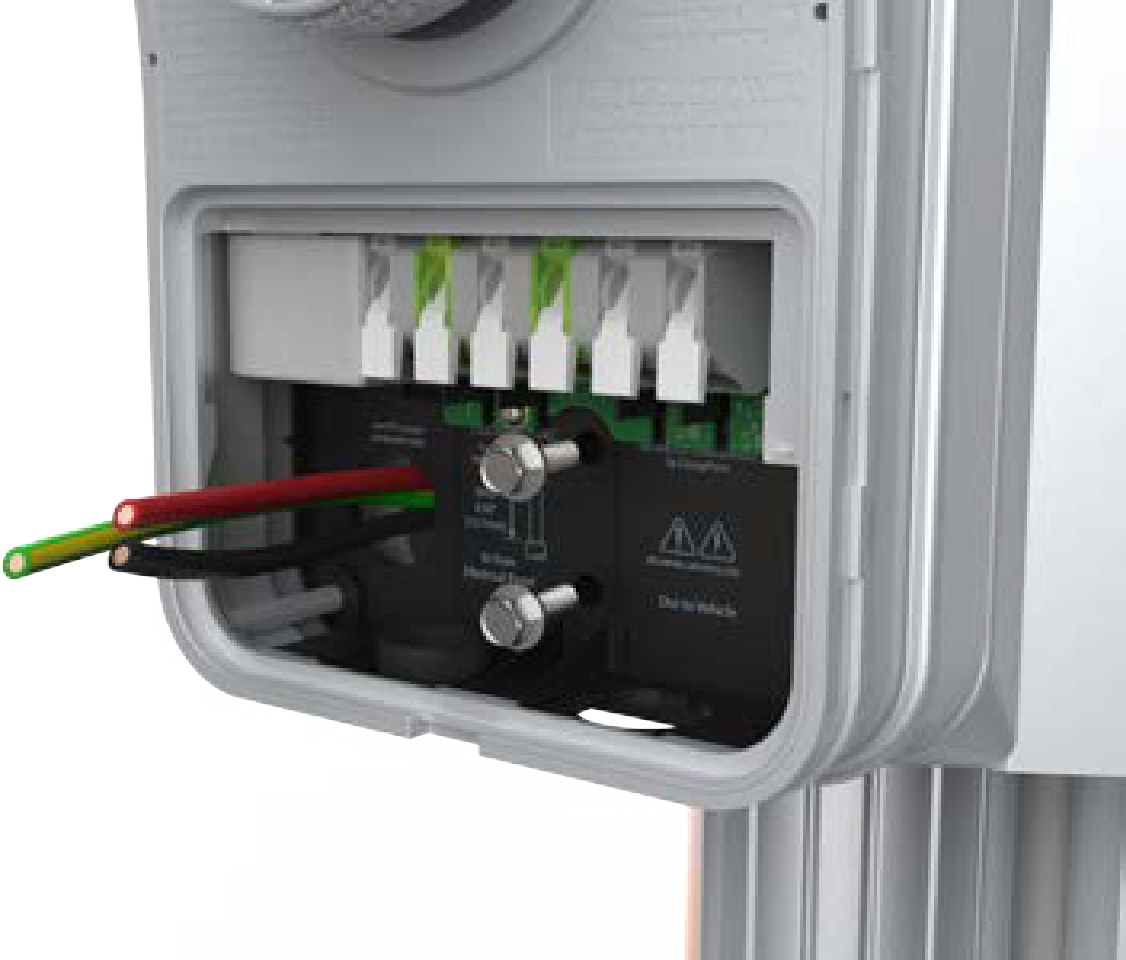
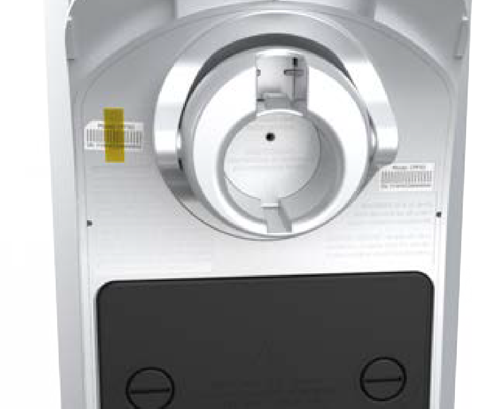
Connect the Service Wiring
-
Ensure that the service wiring can easily reach the connectors on the charging station’s terminal block.
If mounting the CPF50 on an exterior wall and bringing power through the rear knockout, apply sealant around the rear knockout to prevent water ingress.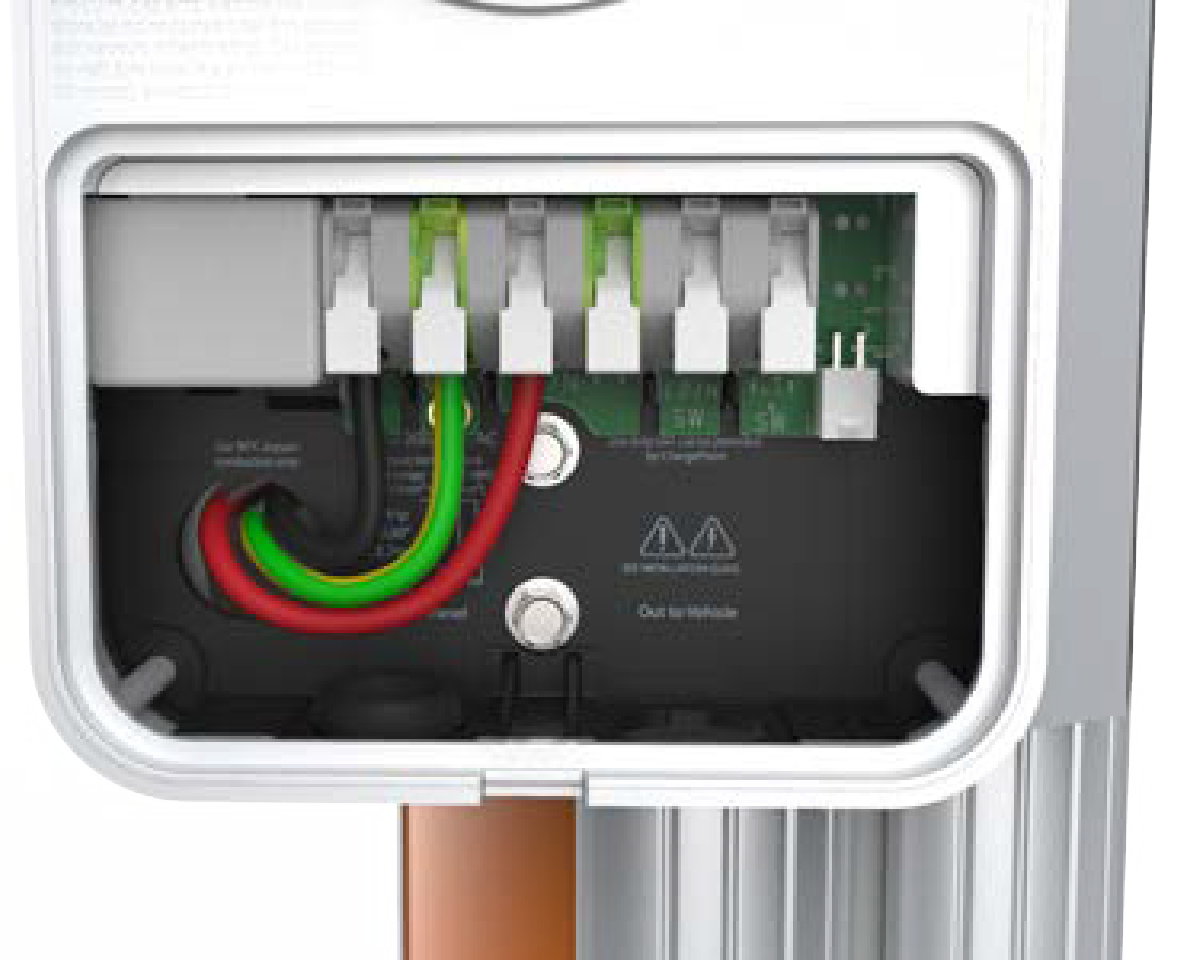
-
Trim the wiring to reduce excess length if any.
-
Strip each wire to 12 mm (1/2 inch).
-
Ensure that the white clips on the terminal block are fully open.
-
Insert the wires into the connectors on the left side of the terminal block.
-
On each connector, press down the three levers until they snap into place.
Ensure that each wire is fully inserted into the connector with no bare wire visible before pressing it into place with the white clip.
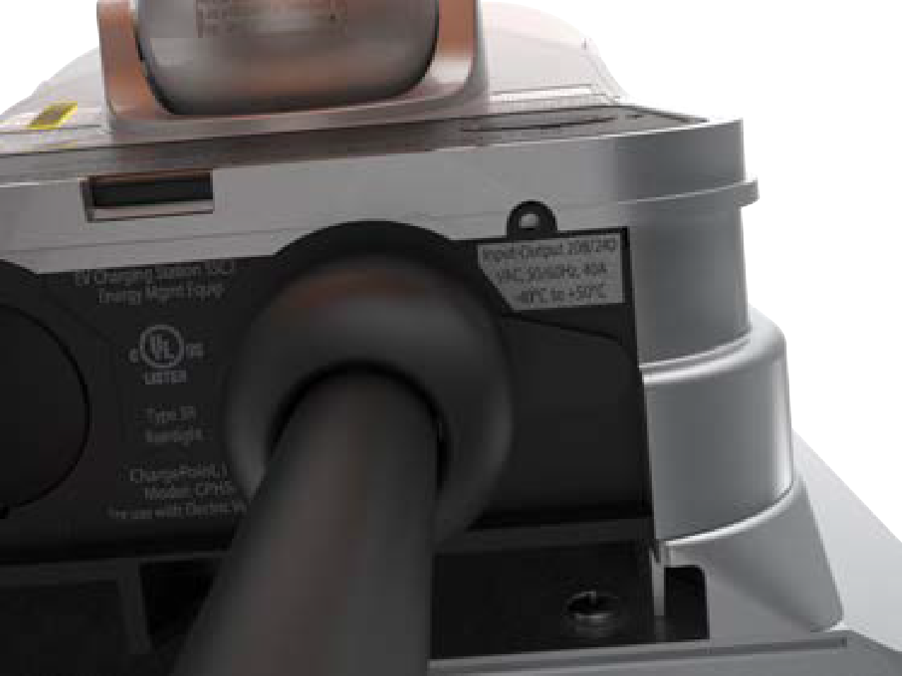
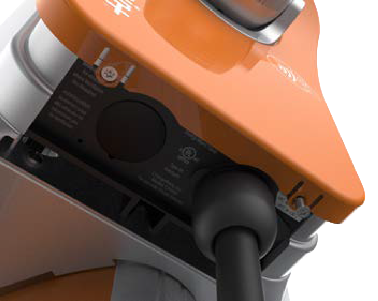
Connect the Charging Cable
-
Remove the cable clip connected to the wiring end of the cable, but do not discard it. Save the clip to use later.
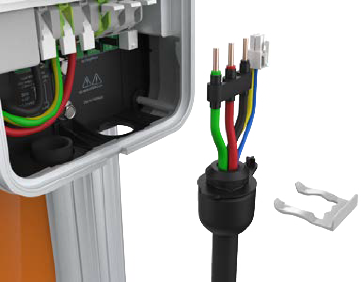
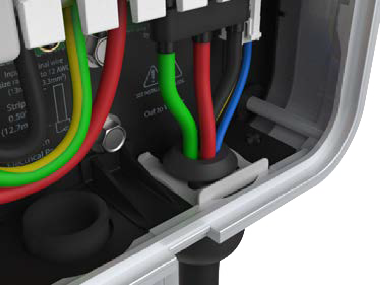
-
Fold the wire ends and insert them into the opening on the lower right side of the station, push up until the cable collar is flush against the enclosure.
-
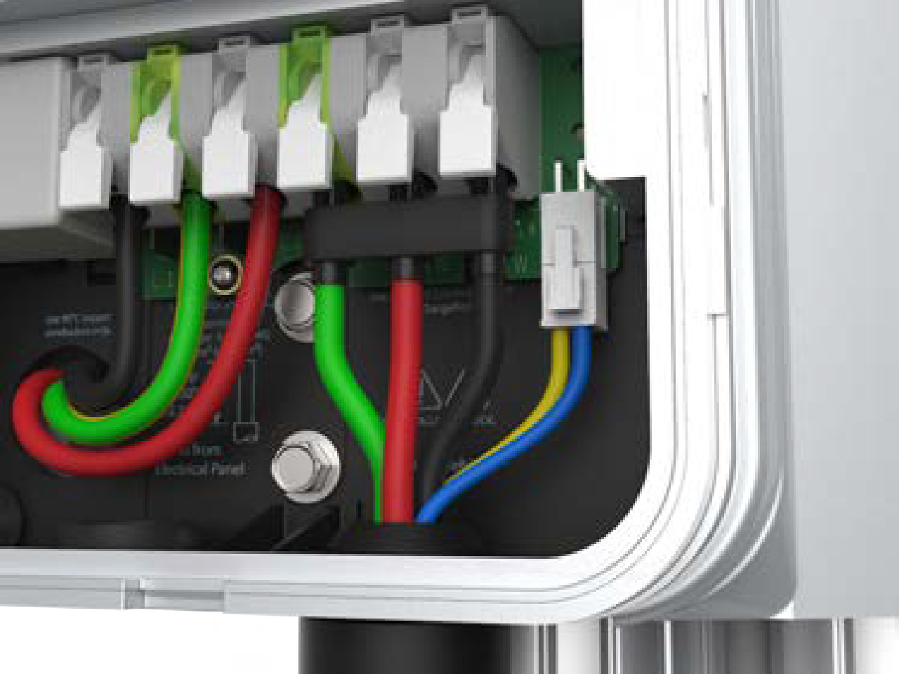
Insert the green wire in the green slot on the left terminal of the output block.
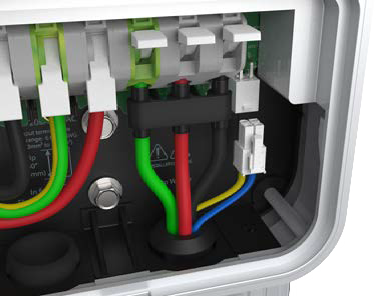
-
Insert the remaining wires into the corresponding connectors on the right side of the terminal block.
-
Push the cables up until the silver conductors are no longer visible.
-
Snap the white levers all the way down on each wire.
Ensure that each wire is fully inserted into the connector with no bare wire visible before pressing it into place with the white clip. -
Insert the 4-pin plug into the connector on the right side of the output supply wiring.
-
While pushing the cable up, slide the cable clip into the slot until it snaps into place. This secures the cable and provides strain relief.
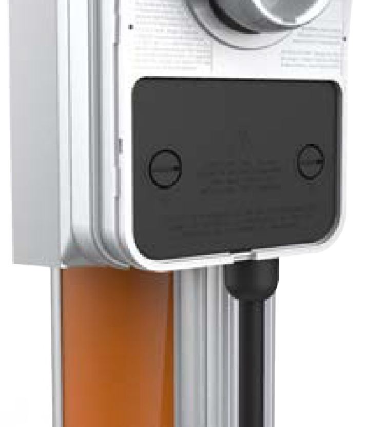
Attach the Wire Cover and Faceplate
-
Place the wire cover over the exposed wiring.
-
Use a coin to lock the wire cover in place.
Do not use a screwdriver as it may damage the wire cover. -
Stick rating label at the bottom of the station over the default rating displayed. The rating label values must match the circuit feeding the charging station.
-
Remove the spare activation label taped to the front of the main unit and place it on the CPF50.
-
Snap the faceplate onto the charging station.
-
Use two T10 Security Torx screws and fasten the faceplate to the bottom of the station.
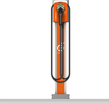
Prepare the Charging Cable for Use
To prepare the charging cable, follow these steps:
For Stations Without a CMK
-
Extend the charging cable to its full length to remove any kinks or twists.
-
Drape the charging cable over the top of the charging station.
-
Insert the connector in its holster.
-
Proceed to Complete Station Setup to complete the station setup.
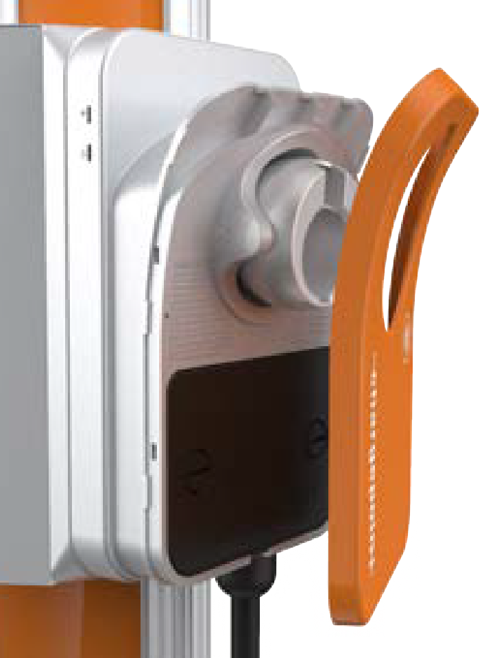
For Stations With a CMK
-
Extend the charging cable to its full length to remove any kinks or twists.
-
Align the knot bearing on each rope to its corresponding mating feature on the cable clamp.
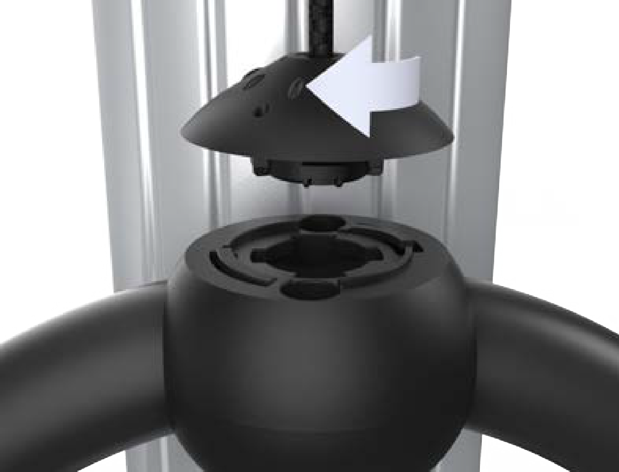
-
Turn the knot bearing clockwise approximately one-quarter turn. Push down gently while turning the knot bearing.
If you are installing a single station CPF50, attach the charging cable on the left side of the station to minimize interference with the RFID Radio Frequency IDentification reader.
-
Proceed to Complete Station Setup to complete the station setup.
