Replace a Charging Cable
To replace a charging cable, complete the following steps.
Required Tools and Materials
|
|
Torx screwdriver (T25, T20) |
|
T25 Security screwdriver |
|
|
10 mm socket hex wrench |
|
Headlamp |
Power Off the Station
Power off at the breaker panel and lock out/tag out before continuing work.
-
Before any procedure, disconnect the power. If station is paired, disconnect the power to both paired charging stations.
-
Follow local code and site lockout/tagout procedure to de-energize the station.
-
Wait for energy to dissipate (approximately five minutes).
-
Keep power off until all covers and panels are reinstalled and the work is complete.
Failure to follow these instructions can result in serious injury, loss of life, or property damage.
Remove the Area Light Bar
To remove the area light bar, complete the following steps:
-
Use a T25 Security screwdriver to loosen the two captive screws on the bottom edge of the area light bar.
When reinstalling the area light bar, route the cable through the notch in the center of the area light bar. Ensure the cable does not get caught between the area light bar and the secondary display controller. Torque to 2.8 Nm (25 in-lb).
-
While holding the area light bar near the opening at the top of the Express 280, disconnect the 4-pin power cable from the area light bar.
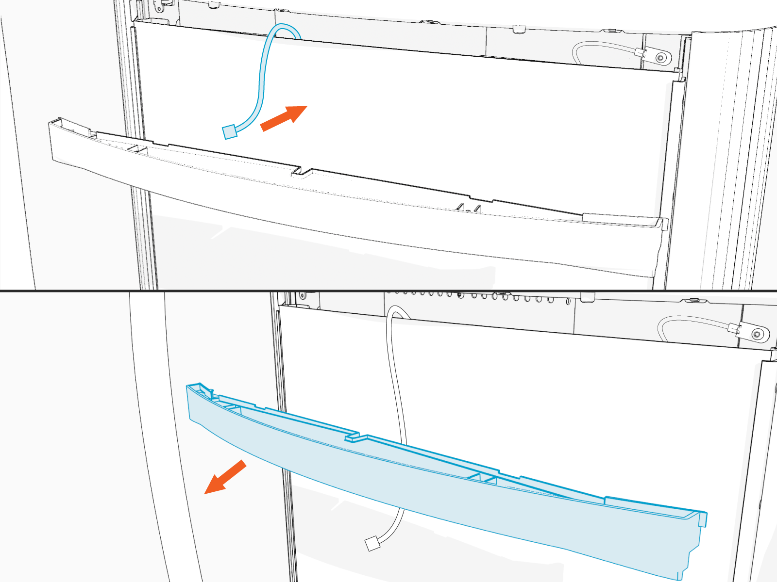
-
Set the area light bar gently on a padded surface.
Remove the Upper Panels and Top Cap
To remove the upper panels and top cap, complete the following steps:
-
Gently pull the middle section of the trim panel out until the tabs clear the side trim. Remove the trim panel.

-
Use both hands to carefully pull the panel away from the station body and lift upward to remove it.

-
Place a protective cover, such as a lint-free cloth, over the touchscreen to prevent damage during service.
-
Use a T25 security screwdriver to loosen the two screws that secure the top of the upper rear panel to the enclosure frame.
When replacing this panel, torque to 4.5 Nm (40 in-lb).
-
Use two hands to pull the upper rear panel away from the station and lift up to remove it.

-
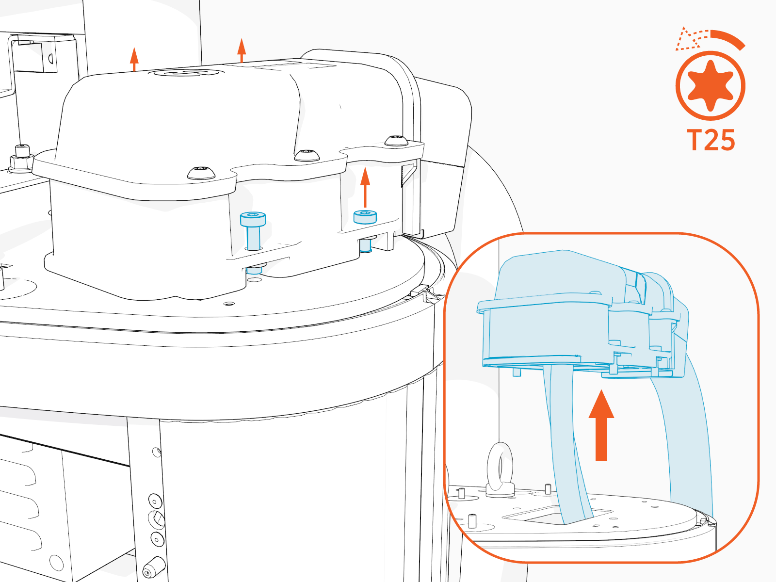
Use a T25 Torx screwdriver to loosen the four screws securing the top cap. Slide the latch to the right to release the tab.

-
Lift the top cap upward to remove it.

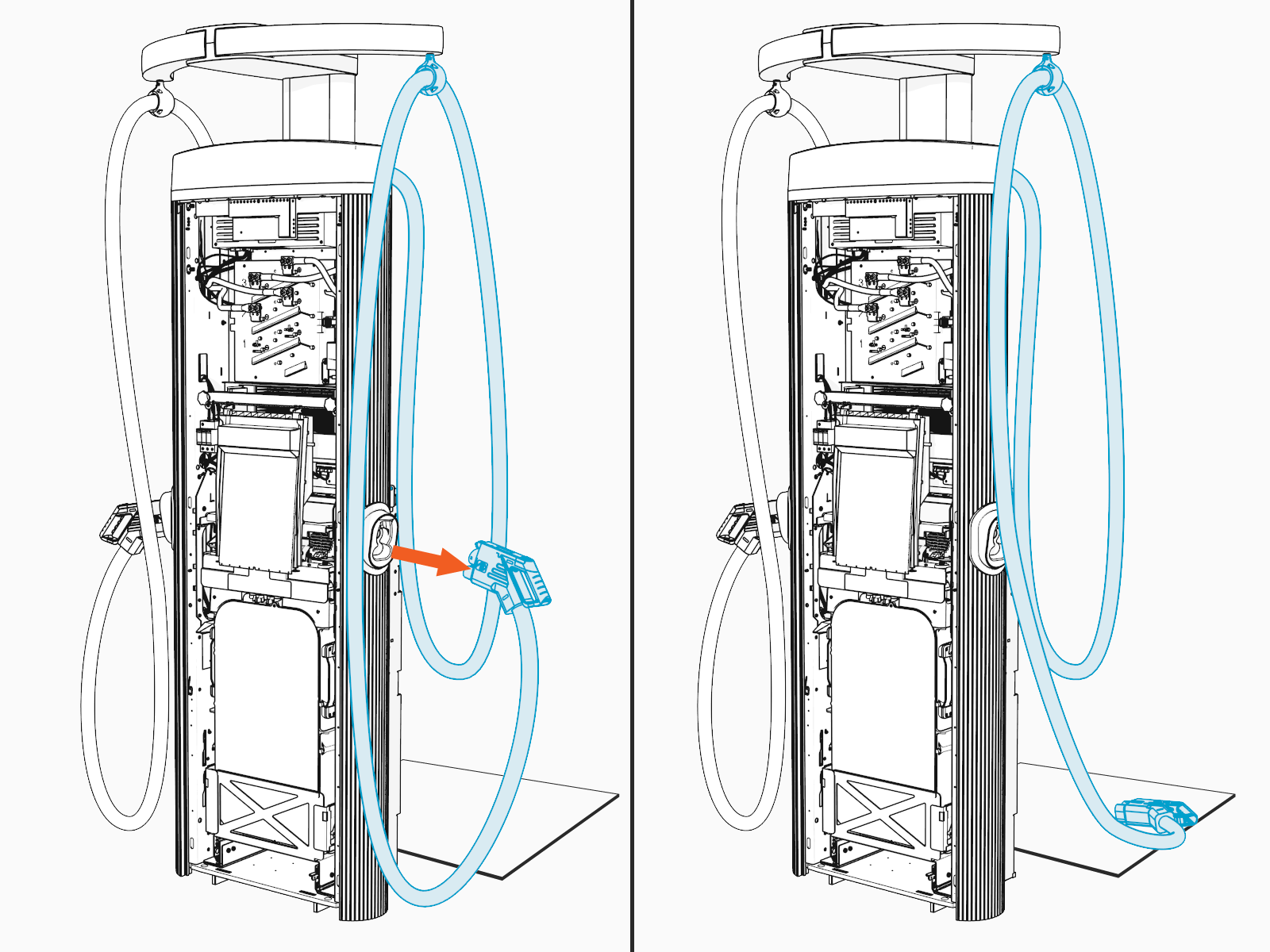
Remove the Charging Cables
To remove the charging cables, complete the following steps:
If you are replacing the charging cable with a NACS![]() North American Charging Standard cable, you must replace the cable on the left side of the station (a).
North American Charging Standard cable, you must replace the cable on the left side of the station (a).
If the station has a CCS![]() Combined Charging System charging cable on the left side and a CHAdeMO charging cable on the right side and you are replacing the CHAdeMO cable with a NACS
Combined Charging System charging cable on the left side and a CHAdeMO charging cable on the right side and you are replacing the CHAdeMO cable with a NACS![]() North American Charging Standard cable, follow these steps:
North American Charging Standard cable, follow these steps:
- Remove both the CCS
 Combined Charging System and CHAdeMO cables.
 - Install the CCS Combined Charging System charging cable on the right side of the station.
- Install the new NACS North American Charging Standard charging cable on the left side.

-
Remove the charging cables and set them down gently on a padded surface.
-
Use a T20 Torx screwdriver to loosen the set screw on the tether ball. Use a flat blade screwdriver to depress the spring while pushing the tether ball up to remove the tether ball.
When replacing the tether ball and cable, align the spring in the ball clamp with the flat notch on the anchor pin. When aligned, push the ball clamp onto the anchor pin. Torque the set screw to 2.8 Nm (25 in-lb).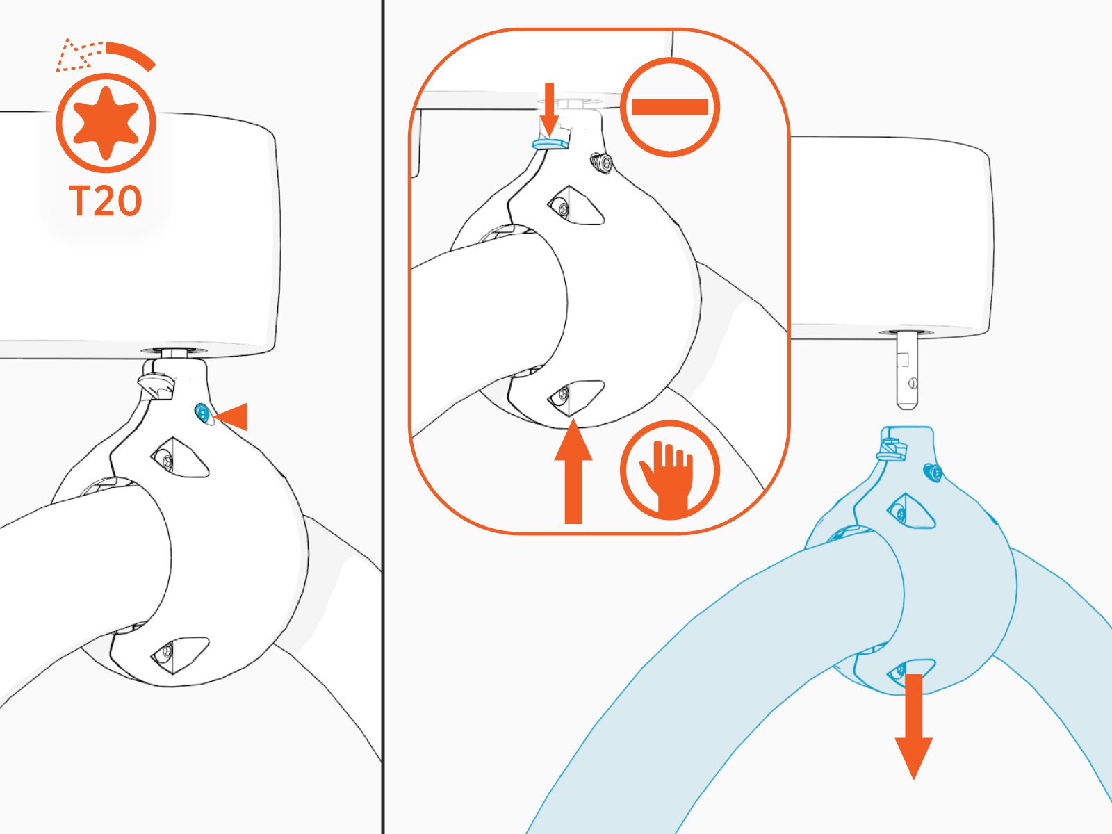
-
Set the charging cable aside gently.

Remove Data and DC Cables
To remove data and DC cables, complete the following steps:
-
Disconnect the data cable extension from the main data cable (a).

-
Use a 10 mm socket hex driver to disconnect the positive and negative conductors from the front tabs of the connector box.
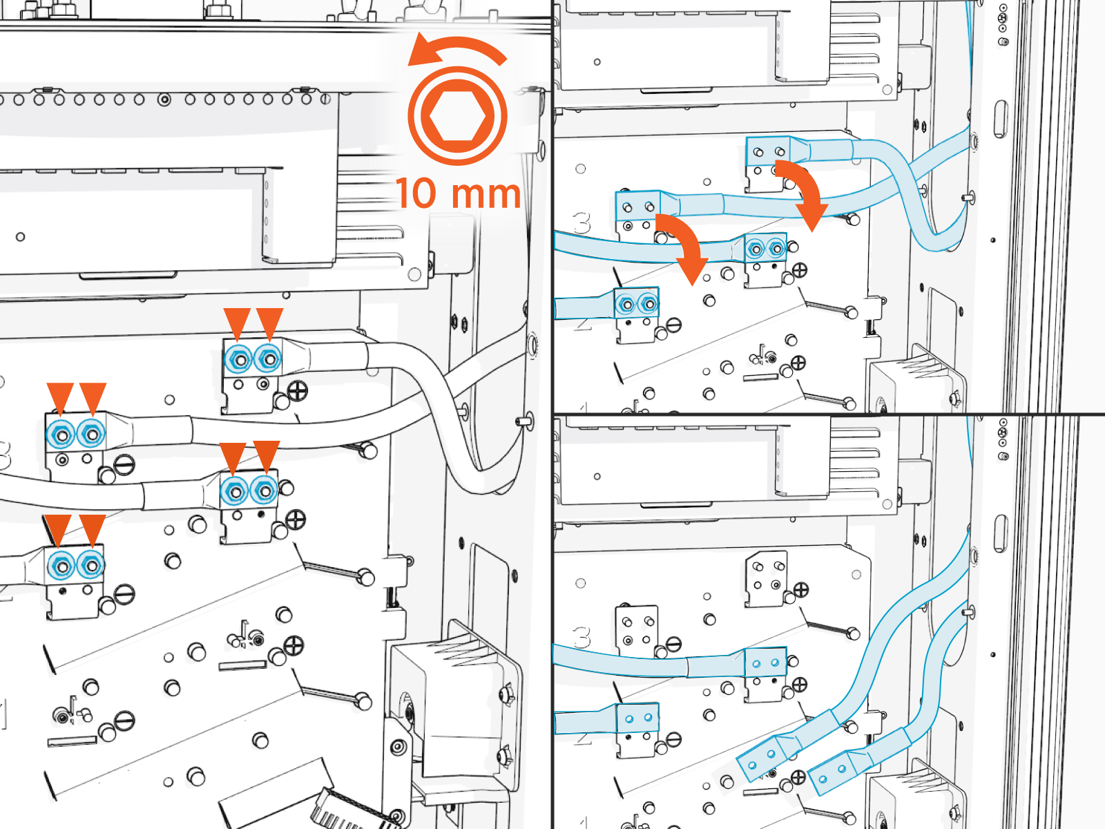
-
Use a T25 Torx screwdriver to loosen the four screws securing the charging cable housing.
-
Remove the DC (a) and data (b) cables. Route the DC cables gently through the ferrite (c) stack.


Install the New Charging Cable
To install the new charging cable, complete the following steps:
-
Guide the DC, ground, and data cables gently through the top of the station.

(a) DC
(b) Ground
(c) Data
-
Route the cables through the ferrite stack.

-
Use a T25 Torx screwdriver to tighten the four screws securing the charging cable housing. Torque to 4.5 Nm (40 in-lb).

-
Apply a thin coat of dielectic grease on each lug.

-
When you are connecting a charging cable on the right side of the station, use a 10 mm socket hex driver to connect the positive and negative DC conductors from the front tabs of the connector box to the upper set of connectors.
 socket hex driver to connect the positive and negative DC conductors from the front tabs of the connector box to the upper set of connectors.")
- Use the middle set of DC connectors for charging cables on the left side of the station.

-
If the station is being configured with two CCS
Combined Charging System charging cables, or if a single CCS Combined Charging System cable is installed, connect a data cable extension to the main data cable.Guide the data cable extension behind the contactor box to connect to the CCS
Combined Charging System cable and the upper data connector.
If the single CCS
Combined Charging System is being installed on the left side when you are standing in front of the station, you do not need the data cable extension. Connect the data cable to the lower data connector. 
REVERSE THE ABOVE STEPS TO REINSTALL THE TETHER BALL, TOP CAP, UPPER PANELS AND AREA LIGHT BAR.
Power On the Station
Ensure all panels are installed before powering station on.
Once all parts are installed, power on the Express 280. The Express 280 runs a self test to verify that it can operate properly.
