Replace the Display
To replace the display assembly, complete the following steps:
Power Off the Station
Power off at the breaker panel and lock out/tag out before continuing work.
-
Before any procedure, disconnect the power. If station is paired, disconnect the power to both paired charging stations.
-
Follow local code and site lockout/tagout procedure to de-energize the station.
-
Wait for energy to dissipate (approximately five minutes).
-
Keep power off until all covers and panels are reinstalled and the work is complete.
Failure to follow these instructions can result in serious injury, loss of life, or property damage.
Before You Begin
Remove the Display
-
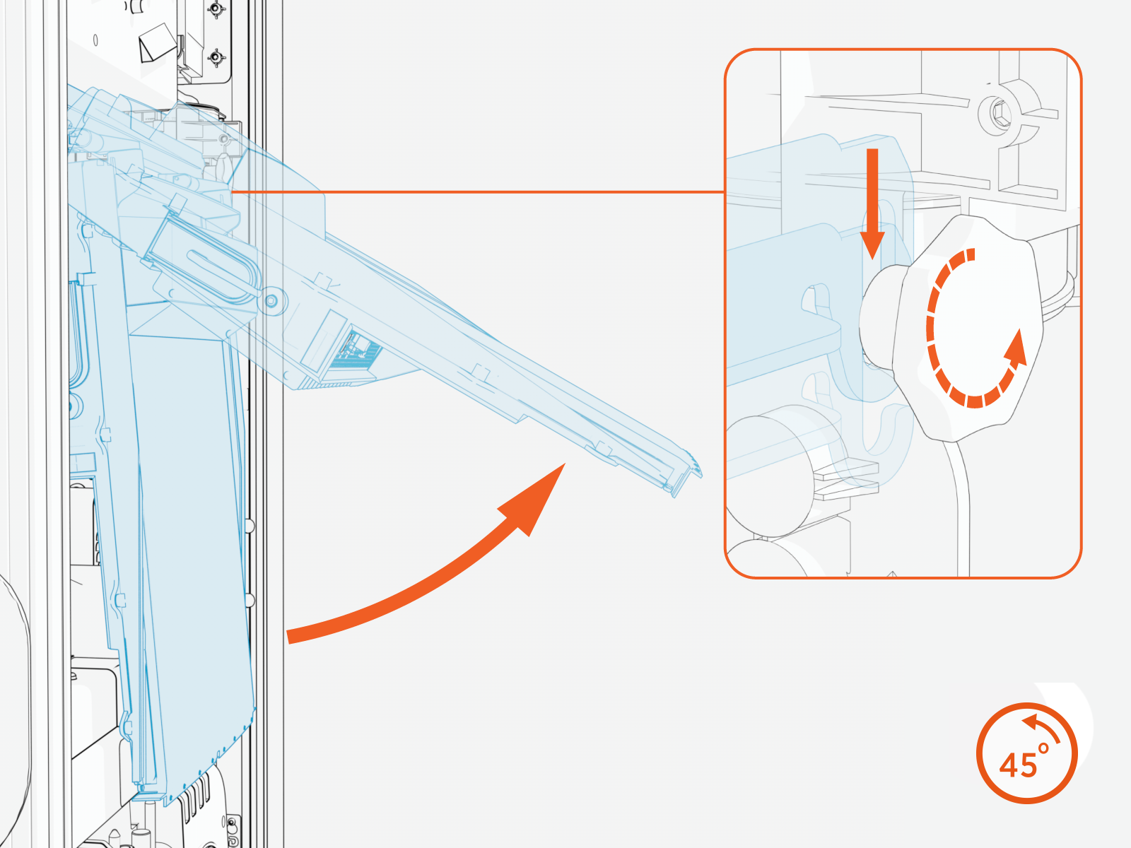
Loosen both retention knobs (a), allowing the display beam (b) to slide up vertically and the display bottom edge to clear the lower front panel slot (c).
.png)
-
Rotate the display upward about the hinge until it reaches a 90-degree position and rotate the retention knobs to re-tighten.

-
Disconnect all cables from the connectors on the bottom of the display and remove them from the wire management rings.
-
While supporting the display, rotate the knobs counterclockwise to loosen them. Then, remove the display from the station.
Install the New Display
To install the display, configure the following steps:
-
Loosen but do not remove the retention knobs.

-
Remove the display from the packaging.

-
Align the hooks of the display mounting bracket over the retention knob supports. Tighten the knobs enough to secure the display.

-
Swing the bottom of the display out to a 90-degree angle.
-
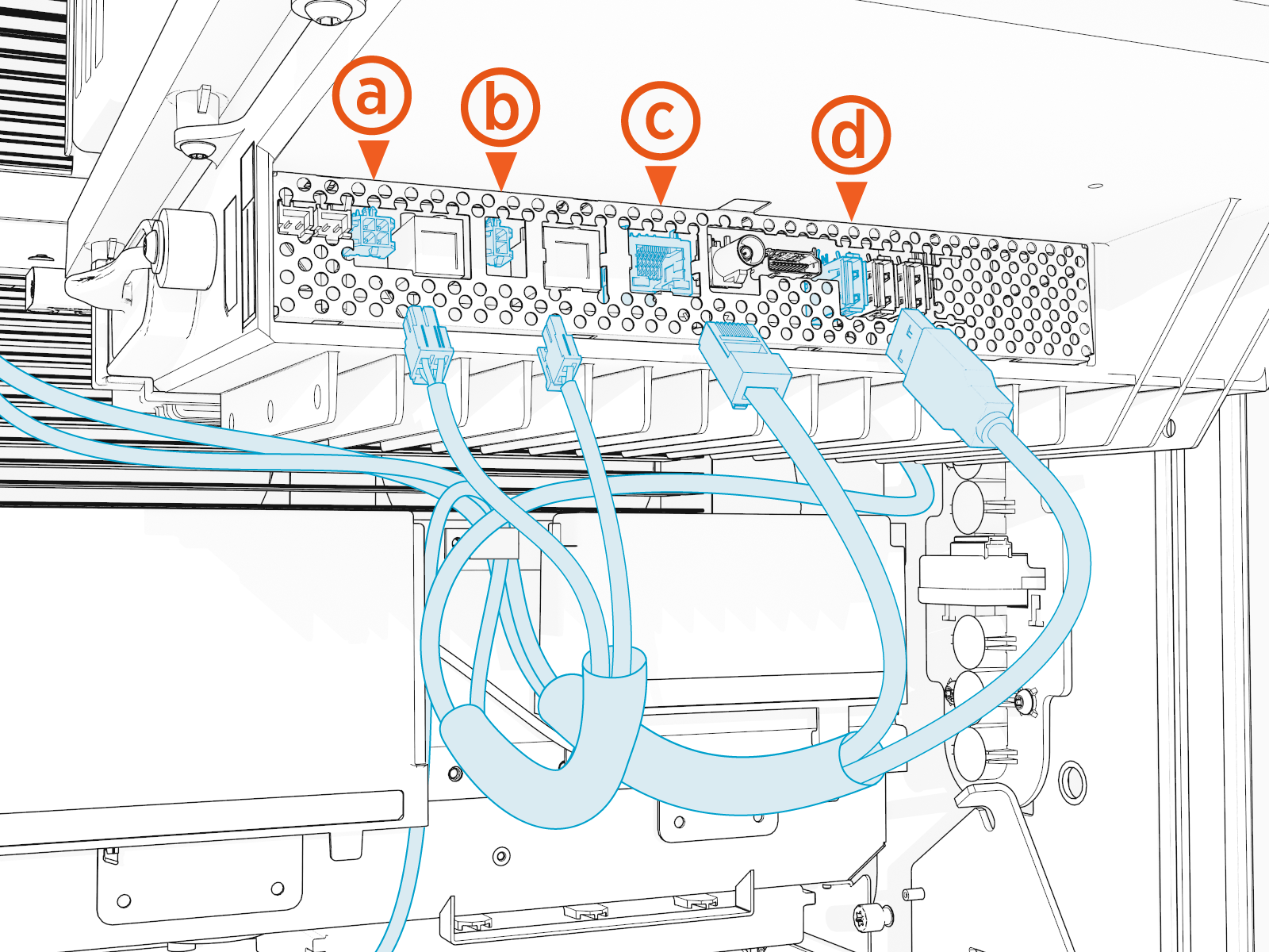
Connect all cables to the underside of the display:
(a) Speaker
(b) Power 24 VDC power
(c) RJ45 to dispenser cable control
(d) USB
 Universal Serial Bus to LED display
Perform a pull-push test to ensure that each cable is correctly seated. Failure to connect these correctly could prevent the system from powering on.
-
Route excess wiring through the wire management rings under the display to prevent it being pinched in the panels.

-
Swing the display down.
Loosen both retention knobs and slide the display beam up.
Re-tighten the knobs.

Reverse the steps in the Remove the Area Light Bar and Remove the Top Front Panel procedures to install the Area Light Bar and Top Front Panel.
Power On the Station
Once all parts are installed, power on the Express 280. The Express 280 runs a self test to verify that it can operate properly.
